CLAAS Tractor Arion 430-410 CLAAS COMPONENT NUMBER Technical Systems Manual – PDF DOWNLOAD
Original price was: $89.00.$28.95Current price is: $28.95.
CLAAS Tractor Arion 430-410 CLAAS COMPONENT NUMBER Technical Systems Manual – PDF DOWNLOAD
Description
CLAAS Tractor Arion 430-410 CLAAS COMPONENT NUMBER Technical Systems Manual – PDF DOWNLOAD
IMAGES PREVIEW OF THE MANUAL:
FILE DETAILS:
CLAAS Tractor Arion 430-410 CLAAS COMPONENT NUMBER Technical Systems Manual – PDF DOWNLOAD
Language : English
Pages :812
Downloadable : Yes
File Type : PDF
Size:95.1 MB
TABLE OF CONTENTS:
CLAAS Tractor Arion 430-410 CLAAS COMPONENT NUMBER Technical Systems Manual – PDF DOWNLOAD
Chapter 00 – CLAAS COMPONENT NUMBER 1
CLAAS component number 1
Numbering of CLAAS components 2
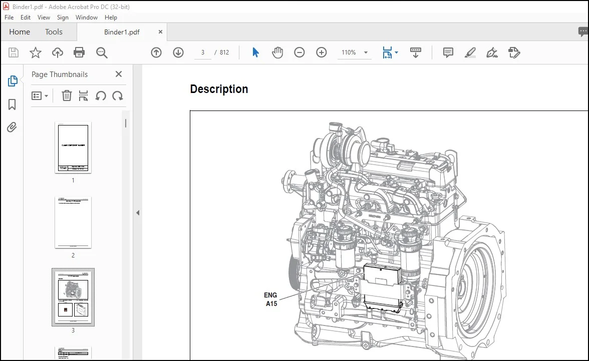
“ENG A15” engine module 3
Description 3
Functions 4
Measurements and checks 4
Inputs/outputs 4
“TR1 A57-1” transmission module 9
Description 9
Functions 10
Schematic diagram 11
Measurements and checks 12
Generic of inputs/outputs 12
Inputs/outputs 13
“TR2 A57-2” transmission module 19
Description 19
Functions 20
Schematic diagram 21
Measurements and checks 22
Generic of inputs/outputs 22
Inputs/outputs 23
“TR3 A57-3” transmission module 27
Description 27
Functions 28
Measurements and checks 28
Schematic diagram 29
Generic of inputs/outputs 30
Inputs/outputs 31
“A58” rear lifting module 35
Description 35
Functions 36
Schematic diagram 37
Measurements and checks 38
Generic of inputs/outputs 38
Inputs/outputs 39
“HYD A60” hydraulic module 45
Description 45
Functions 46
Measurements and checks 46
Generic of inputs/outputs 46
Inputs/outputs 47
Dashboard and “DBD A101” CAN network communication module 51
Description 51
Functions 52
Measurements and checks 52
Inputs/outputs 53
“B42” fuel pressure sensor 59
Description 59
Measurements and checks 59
Power check 59
Checking the sensor output signal 60
Removal 60
Refitting 60
“B44” fuel temperature sensor 61
Description 61
Measurements and checks 62
Power check 62
Checking the output signal 62
Resistance check 63
“B45” coolant temperature sensor 65
Description 65
Measurements and checks 65
Power check 65
Resistance check 66
Transmission oil temperature sensor “B123” 67
Description 67
Measurements and checks 68
Power check 68
Position sensor for rear lifting “B139” 69
Description 69
Adjustment 70
“GPA 22” rear axle 70
Measurements and checks 70
Power check 70
Signal voltage check 70
“B142” power take-off engine speed sensor 71
Description 71
Adjustment 72
Measurements and checks 72
Frequency check 72
Resistance check 72
Left “B144-1” and right “B144-2” force sensors 73
Description 73
Measurements and checks 74
Voltage test 74
Output voltages according to force type and load 74
“B222” intake fresh air temperature sensor 75
Description 75
Measurements and checks 76
Power check 76
Resistance check 76
“B225” water in fuel sensor 77
Description 77
Measurements and checks 77
Power check 77
Theoretical speed sensor “B227” 79
Description 79
Adjustment 80
Measurements and checks 81
Frequency check 81
Resistance check 81
Engine speed sensor (on power take-off clutch housing) “B228” 83
Description 83
Adjustment 84
Measurements and checks 84
Resistance check 84
“B229” gearbox speed intermediate sensor 85
Description 85
Adjustment 86
Measurement and control 86
Resistance check 86
Frequency check 86
“B231” crankshaft position and engine speed sensor 87
Description 87
Measurements and checks 88
Power check 88
Resistance check 88
Frequency check 88
“B232” timing position and engine speed sensor 89
Description 89
Measurements and checks 90
Power check 90
Resistance check 90
Frequency check 90
Electrohydraulic valve (A) “B366” command 91
Description 91
Measurements and checks 92
Power check 92
Signal check 92
Electrohydraulic valve (B) “B367” command 93
Description 93
Measurements and checks 94
Power check 94
Signal check 94
Electrohydraulic cross control “C60” 95
Description 95
Measurements and checks 96
Checking the power supply of the “C60” cross command 96
Checking the power supply of the “+” and “-” “S269” speed switch 96
“M41” recycling actuator 97
Description 97
Measurements and checks 98
Cold-start resistance “R15” 99
Description 99
Measurements and checks100
Check of the glow plug supply100
Fuel level “R35″101
Description101
Measurements and checks102
Resistance check102
“R71” Accelerator pedal position angular sensor103
Description103
Adjustment104
Measurements and checks105
Checking the sensor supply105
Checking the sensor output signal105
“R73” pedal position angular sensor107
Description107
Adjustments108
Measurements and checks110
Checking the sensor supply110
Checking the sensor output signal110
“S1” 4-wheel drive switch111
Description111
Measurements and checks112
Supply voltage112
Key operated ignition “S64”113
Description113
Measurements and checks114
Power check114
“S94” differential locking switch115
Description115
Measurements and checks116
Continuity test116
Power check116
On/off contact of the forward PTO “S113″117
Measurements and checks118
Continuity check118
Power check118
“S114” power take-off on/off contact119
Continuity check120
Power check120
Forward/reverse lever “Revershift S171”121
Description121
Measurements and checks122
Power check122
“S172” power take-off automation contact123
Description123
Measurements and checks124
Power check124
“S173” power take-off brake contact125
Description125
Measurements and checks126
Power check126
“+/-” gear and “S184” clutch contacts127
Description127
Measurements and checks128
Power check128
Checking the output voltage128
“S193” work/transport mode switch129
Description129
Measurements and checks130
Power check130
Switch of the “S194” auxiliary hydraulics131
Description131
Measurements and checks132
Power check132
Continuity check132
“F3 S230” and “F4 S231” function switch133
Description133
Measurements and checks133
Checking the output voltage133
Safety contact of the “S232” cross command135
Description135
Measurements and checks135
Checking the output voltage135
Quick tool command locking switch “S233″137
Description137
Measurements and checks137
Checking the output voltage137
Float position switch “S234″139
Description139
Measurements and checks139
Checking the output voltage139
Switch of the “Quadractiv S254” function141
Description141
Measurements and checks142
Power check142
All-flows switch “S265″143
Description143
Measurements and checks144
Power check144
Continuity check144
Switch of the “+” and “-” “S269” gears145
Description145
Measurements and checks145
Power check145
Checking the output voltage145
“U50” rear power take-off on/off contact147
Description147
Measurements and checks148
Supply voltage148
“U53” rear power take-off emergency stop contact149
Description149
Measurements and checks150
Power check150
Rear contact of “U57”, “U58” rear lifting151
Description151
Measurements and checks152
Power check152
Checking the output voltage152
Resistance check152
“V22” lifting control panel153
Description153
Functions154
Measurements and checks154
Inputs/outputs154
“Y1” 4-wheel drive solenoid valve157
Description157
Measurements and checks158
Power check158
Resistance check158
Differential lock solenoid valve “Y105”159
Description159
Measurements and checks160
Power check160
Resistance check160
“Y320” electronic injector161
Description161
Adjustments162
Measurements and checks162
Checking the solenoid’s supply162
Checking the solenoid’s resistance162
“Y325” rear power take-off clutch solenoid valve163
Description163
Measurements and checks164
Checking intensity164
Resistance check164
“Revershift” solenoids, “Y327” and “Y328”165
Description165
Measurements and checks166
Resistance check166
Checking intensity166
Gear solenoid valve under “Y335” torque167
Description167
Measurements and checks168
Checking the supply and the intensity168
Resistance check168
Up/down solenoids valve of rear lifting “Y336”, “Y337”169
Description169
Measurements and checks170
Checking intensity170
Checking the resistance of the solenoid valve170
PTO brake solenoid valve “Y338”171
Description171
Measurements and checks172
Power check172
Resistance check172
“Y339” robot-driven solenoid valve173
Description173
Measurements and checks174
Checking the supply and the intensity174
Resistance check174
Air brake solenoid valve “Y340”175
Description175
Measurements and checks176
Power check176
Resistance check176
“Y344” dosage solenoid valve (high pressure pump)177
Description177
Measurements and checks177
Checking the resistance of the solenoid valve177
Solenoid valve for coupling the “Y492” hydraulic pumps179
Description179
Measurements and checks180
Power check180
Resistance check180
“Z5” presence contact181
Description181
Measurements and checks182
Power check182
Resistance check182
“Z12” handbrake contact183
Description183
Measurements and checks183
Supply voltage183
“Z21” A/C gas pressure switch185
Description185
Measurements and checks185
“Z24” A/C thermostat187
Description187
Measurements and checks188
“Z42” engine oil pressure switch189
Description189
Measurements and checks190
Continuity check190
Power check190
“Z69” air filter clogging contact191
Description191
Measurements and checks191
Power check191
Continuity check191
“Z76” brake fluid level contact193
Description193
Measurements and checks193
Continuity test193
Voltage test193
“Z102” high pressure filter clogging pressure switch195
Description195
Measurements and checks196
Power check196
Continuity check196
“Z126” left brake pedal contact197
Description197
Measurements and checks198
Supply voltage198
Adjustment198
“Z127” right brake pedal contact199
Description199
Measurements and checks200
Supply voltage200
Adjustment200
“Z150” slow range contact201
Description201
Measurements and checks202
Power check202
“Z152” pedal in low position contact203
Description203
Adjustments204
Measurements and checks205
Voltage test205
Range switch “Z153”207
Description207
Measurements and checks208
Power check208
“Z159” economic 540 power take-off contact209
Description209
Measurements and checks210
Continuity check210
Power check210
“Z160” 1 000 rev/min power take-off contact211
Description211
Adjustment212
Measurements and checks212
Continuity check212
Power check212
“Z162” proportional power take-off contact213
Description213
Measurements and checks214
Continuity check214
Power check214
Suction circuit pressure switch “Z183”215
Description215
Measurements and checks216
Power check216
Continuity check216
Low pressure switch “Z184”217
Description217
Measurements and checks218
Voltage test218
Test methods219
Accumulator225
Voltage test225
Charging test225
Electronic unit227
Voltage test227
Frequency test227
Current test227
“Auto-5” electronic unit229
Voltage test229
Frequency test229
Current test229
Unit internal electronics test230
Water sensor231
Resistance test231
Hall effect sensor233
Voltage test233
Current test233
Variable reluctance induction sensor235
Voltage test235
Resistance test235
Flexible blade sensor237
Magneto-elastic sensor239
Voltage test239
Pressure sensor (Rheostat)241
Voltage test241
Temperature sensor (thermistor)243
Resistance test243
Supply circuit switch245
Continuity test245
Voltage test245
Detection contact247
Resistance test247
Voltage test247
Earthing switch249
Continuity test249
Voltage test249
Proportional solenoid valve251
Resistance test251
On/off solenoid valve253
Voltage test253
Resistance test253
Current test253
Control lever255
Voltage test255
Electric motor257
Voltage test257
Current test257
Photo-resistance259
Resistance test259
Potentiometer261
Resistance test261
Radar263
Voltage test263
Relay265
Resistance test265
Voltage test265
Resistance267
Resistance test267
Solenoid269
Voltage test269
Resistance test269
Current test269
Chapter 00 – ERROR CODES271
Error codes271
Introduction276
Display of error codes277
Description of the error codes list278
Error code278
Native code278
Sender module278
Designation278
Cause278
Comment279
List of error codes280
Chapter 00 – Symbols, Fixing and sealing products, Pneumatic lines, Hydraulic lines, Standardised torques309
Symbols309
Fixing and sealing products309
Pneumatic lines310
Hydraulic lines310
Standardised torques (except specific torque for technical support)311
Hardware class311
Hydraulic fittings DIN 3865 standard312
Chapter 01 – ENGINE313
01 Engine317
Torque settings and sealants319
Checking power/torque321
List of checks321
Checking hydraulic pressure325
Centre circuit open 60 and 98 l/min325
Power/torque reference values Arion 430 CIS327
Power/torque reference values Arion 430328
Power/torque reference values Arion 420 CIS329
Power/torque reference values Arion 420330
Power/torque reference values Arion 410 CIS331
Power/torque reference values Arion 410332
Measurements and checks333
Checking the fuel supply pressure333
Compression check333
Lubrication pressure check334
Checking the turbocharger pressure335
Checking the thermostat336
Results record form337
Power/Torque337
Power take-off position 1 000 rev/min337
Diesel fuel supply pressure337
Compressions338
Lubrication pressure338
Turbocharger pressure338
Thermostat339
Chapter 02 – TRANSMISSION CLUTCH341
02 TRANSMISSION/CLUTCH341
General345
Tightening torques and sealing compounds of the gearbox347
Main shimming348
Engine coupling – “Quadrishift”349
“Quadrishift” coupling – ranges350
Range module/rear axle coupling351
Couples specific products and sealants circuit steering352
Tightening torques and sealing compounds of the rear axle353
Main shimming of the rear axle355
Tightening torques and sealing compounds of the “HD” shaft tube357
Main shimmings of the “HD” shaft tube357
Transmission kinematics358
“Revershift” hydraulic reverser359
Adjustment of the clutch pedal360
“Revershift” calibration361
Manual adjustment of progressivity362
Arion 400 – With “CIS”362
Arion 400 – Without “CIS”362
Measurements and checks363
Control of general lubrication pressure363
Results record form364
Control of general lubrication pressure364
Measurements and checks365
Checking the general rating pressure365
Checking the rating pressure of the accumulators365
Checking the nirogen load365
Hydraulic control365
Check of the control law under “Revershift” torque366
Results record form367
Checking the general rating pressure367
Checking the accumulator rating pressure367
Check of the control law under “Revershift” torque367
“Quadrishift” reducer under load369
Measurements and checks370
Control of general lubrication pressure370
Results record form371
Control of general lubrication pressure371
Measurements and checks372
Checking the general rating pressure372
Checking the rating pressure of the accumulators372
Checking the nirogen load372
Hydraulic control372
Checking the “Quadrishift” driving law373
Results record form374
Checking the general rating pressure374
Checking the rating pressure of the accumulators374
Checking the piloting law of the “Quadrishift” module374
‘Robot-driven ranges’ mechanical reducer375
Measurements and checks376
Control of general lubrication pressure376
Results record form377
Control of general lubrication pressure377
Measurements and checks378
Checking the general rating pressure378
Checking the rating pressure of the accumulators378
Checking the nirogen load378
Hydraulic control378
Results record form379
Checking the general rating pressure379
Checking the rating pressure of the accumulators379
Lubrication381
Checking the lubrication flow of the “Revershift” clutch and the “Quadrishift” set382
Checking the lubrication flow of the lower shaft ranges and reverse transmission shaft383
Checking the lubrication flow of the upper range shaft and forward drive clutch384
Results record form385
Lubrication flow control385
Cooling387
Checking the flow rate and pressure at the cooler inlet388
Checking the flow rate and pressure at cooler outlet389
Results record form390
Checking the flow rate and pressure at the cooler inlet390
Checking the flow rate and pressure at cooler outlet390
Rear axle391
Measurements and checks392
Checking the rear axle lubrication pressure and flow rate392
Results record form393
Checking the rear axle lubrication pressure and flow rate393
Differential395
Measurements and checks396
Control of differential locking engaging pressure396
Results record form397
Control of differential locking engaging pressure397
Electro-hydraulic PTO399
Measurements and checks400
Checking the front axle engagement pressure (4 wheel drive)400
Results record form401
Checking the front axle engagement pressure (4 wheel drive)401
Chapter 03 – FRAME403
03 Frame403
Front wheel drive steering axle407
Kinematics of the 2019 and 2022 front axles408
Torque settings and sealants409
Chapter 04 – BRAKES411
04 Brakes411
Foot brake415
Measurements and checks416
Checking the lubrication pressure and flow of the service brakes (after valve)416
Checking pressure of the service brake (master cylinder + boosters) and trailer hydraulic, pneumatic brake417
“Booster” chart418
Results record form419
Checking the lubrication pressure and flow of the service brakes (after valve)419
Checking pressure of the service brake (master cylinder + boosters) and trailer hydraulic, pneumatic brake419
Trailer air brake421
Schematic diagram423
Pneumatic diagram424
Torque settings426
Measurements and checks427
Checking pressure in the pneumatic braking circuit427
Results record form428
Checking pressure in the pneumatic braking circuit428
Trailer hydraulic brake429
Measurements and checks430
Checking pressure of the trailer hydraulic brake430
Results record form430
Checking pressure of the trailer hydraulic brake430
Chapter 05 – STEERING431
05 Steering431
Adjustment435
Adjusting parallelism on rigid front axle435
Adjusting the steering stops435
Specific torques and sealing compounds436
Specific torques and sealing compounds436
Measurements and checks 60 and 98 l/min437
Steering pump check (15 cm³ pump)437
Checking the flow rate from the steering unit and control pressure438
Checking maximum steering actuator pressure439
Shockproof valve opening pressure check440
Recording sheets 60 and 98 l/min442
Steering pump check (15 cm³ pump)442
Checking the flow rate from the steering unit and control pressure442
Checking maximum steering actuator pressure442
Shockproof valve opening pressure check442
Chapter 06 – LIFTING DEVICE443
06 Lifting device443
60 and 98 l/min rear lifting447
To unlock447
Adjustment447
Calibration of the TCE 15 T rear lifting447
Reset: Acquisition of factory values448
Specific torques and sealing compounds449
Measurements and checks450
Checking the supply flow to the lifting valve (14 cm¸ pump)450
Checking the supply pressure of the rear lifting jacks (14 cm¸ pump)452
Checking the opening pressure of the rear lifting “7150” shock valve453
Recording sheets 60 and 98 l/min454
Checking the supply flow to the lifting valve (14 cm3 pump) on the 60 l/min circuit454
Checking the supply flow to the lifting valve (14 cm3 pump) on the 98 l/min circuit454
Checking the supply pressure of the rear lifting jacks (14 cm¸ pump)454
Checking the opening pressure of the rear lifting “7150” shock valve454
Front linkage455
Assembly without front loader455
Assembly with front loader455
Measurements and checks456
Checking the supply pressure of the jacks456
Results record form457
Jack pressure457
Front loader458
Torque settings – Refer to section: 06 Repair458
Hydraulic cylinder of the “Flexpilot” valve (Open centre)458
Check the loader hydraulic supply459
Check the “Flexpilot” valve459
Checking the supply pressure of the “Flexpilot” lever459
Checking the control pressure460
Check the accumulator461
Check the loader’s power supply462
Chapter 08 – POWER AND CONTROL OUTPUTS463
08 Power and control outputs463
Front power take-off467
Specific torques and sealing compounds467
Measurements and checks468
Checking low pressure of the front power take-off468
Checking pressure of the front power take-off command469
Results record form470
Checking low pressure of the front power take-off470
Checking pressure of the front power take-off command470
Rear power take-off471
Measurements and checks471
Checking supply pressure of the rear PTO clutch471
Checking pressure of the rear power take-off brake472
Check the rear power take-off lubrication flow rate473
Checking lubrication pressure of the rear power take-off474
Results record form475
Checking supply pressure of the rear PTO clutch475
Checking pressure of the rear power take-off brake475
Check the rear power take-off lubrication flow rate475
Checking lubrication pressure of the rear power take-off475
Chapter 09 – HYDRAULIC SYSTEM477
09 Hydraulic system477
Pumps481
Torque settings and sealants481
HYDRAULIC SYSTEM482
60 L/min circuit482
98 l/min circuit without solenoid valve483
98 l/min circuit with Sauer Danfoss “PVG 32” solenoid valve484
Localization of the lubrication on 60 l/min and 98 l/min485
CLAAS Component Number486
Hydraulic component family486
List of hydraulic components487
Measurements and checks – Centre circuit open 60 and 98 l/min490
Checking the control pressure490
Checking pressure of the 14 cm3 pump491
Checking pressure of the 19 cm3 pump492
Control of general lubrication pressure493
Checking the rating pressure of the accumulators494
Checking the nirogen load494
Hydraulic control494
Recording sheets 60 and 98 l/min495
Checking the control pressure495
Checking pressure of the 14 cm3 pump495
Checking pressure of the 19 cm3 pump495
Control of general lubrication pressure495
Checking the accumulator rating pressure495
Auxiliary spool valves496
Specific torques and sealing compounds496
Measurements and checks 60 and 98 l/min497
Auixiliary spool valve supply pressure check (19 cm¸ pump)497
Checking the flow divider on valve No1498
Checking pressure and flow on the auxiliary valve (1) fitted with a flow divider499
Checking pressure and flow on auxiliary valves (2), (3) or (4)500
Checking pressure and flow on the auxiliary solenoid valve (A) or (B)501
Checking pump flow at the inlet of auxiliary valves502
Recording sheets 60 and 98 l/min503
Auixiliary spool valve supply pressure check (19 cm¸ pump)503
Checking the flow divider on valve No1503
Checking pressure and flow on the auxiliary valve (1) fitted with a flow divider503
Checking pressure and flow on auxiliary valves (2), (3) or (4)504
Checking pressure and flow on the auxiliary solenoid valve (A) or (B)504
Checking pump flow at the inlet of auxiliary valves504
Chapter 10 – ELECTRIC SYSTEM505
10 Electric system505
bus CAN networks509
Description of the bus CAN network510
Checking the bus CAN network511
Checking the equivalent resistance of the “Powertrain CAN bus” network511
Checking the equivalent resistance of the “CLAAS vehicle CAN bus” network511
Checking the equivalent resistance of the “Hydraulic CAN bus” network512
Differentiators and differentiator + resistors512
Location and checking the “Powertrain CAN bus” resistors513
Location513
Check513
Location and checking the “CLAAS vehicle CAN bus” resistors514
Location of the resistors514
Checking the resistors514
Location and checking the “Hydraulic CAN bus” resistors515
Location of the resistors515
Checking the resistors515
Location of the “Powertrain”, “Hydraulic” and “CLAAS vehicle CAN bus” differentiators516
“Powertrain CAN bus” differentiator516
“CLAAS vehicle CAN bus” differentiator517
“Hydraulic CAN bus” differentiator517
10 ELECTRICAL SERVICES519
Technical support user guide521
F0 GENERAL523
CLAAS COMPONENT NUMBERS (CCN) list527
List of connectors532
GENERAL WIRING542
List of harnesses543
List of grounding points544
Fuse plates and electronic plates545
Primary services fuse plate V21-1545
Fuse plate top cab V21-3550
F1 FUNCTION DIAGRAMS 555
Front working lights on cab roof561
Rear working lights on cab roof562
Position and police plate lights563
Dipped headlights564
Low beam with upper cab tilting565
Main beam lights566
Brake lights567
Rotating beacons568
Horn569
Flashing indicators and hazard warning lights570
Instrument panel lighting571
Fan control572
manual air conditioning573
Rear lift574
Front power take-off575
Rear power take-off576
Starting and loading circuit577
Pre-heating578
Forward – Reverse579
Robot-driven ranges580
4-wheel drive control581
Differential control582
Hydraulic pressure – Oil filter blocked583
Crawl range584
Transmission temperature585
Quadrishift586
Work/transport mode587
Robot-driven and Quadrishift range control588
Quadractive589
Cigarette lighter590
Radio591
Overhead light592
Front windscreen wash/wipe593
Rear screen wiper/washer594
Powertain CAN Bus595
CLAAS vehicle CAN bus596
Hydraulic CAN bus597
Supply before contact598
Supply after contact599
Earth600
Supply of transmission modules (“TR1”, “TR2”, “TR3”)601
Rear lifting module (“REH”) and control panel power supply602
Engine module power supply (“ENG”)603
Diagnostic socket power supply604
Electrodistributor module power supply (“VALVE”) – (HYD) hydraulic module605
Dashboard module power supply (“DBD”)606
25A power socket (cab)607
Charger plug supply608
Pneumatic brake609
Braking CUNA610
Handbrake611
Pneumatic seat612
Presence sensor613
Theoretical forward speed and transmission load614
Fuel gauge615
Brake fluid level616
Oil pressure – Air filter blocked – Coolant temperature617
Electronic injection – 4 cylinders618
Engine speed619
Calibration, dashboard display620
Dashboard selector “CIS”621
Electrohydraulic valves commands622
Total flows623
Notes624
F2 CONNECTOR DIAGRAMS625
J003 Connector – V21-1 base plate634
J004 Connector – V21-1 base plate635
J005 Connector – V21-1 base plate636
J006 Connector – Controller Area Network (CAN)636
J007 Connector – Controller Area Network (CAN)637
J008 Connector – PSI base plate637
J009 Connector – Compressor638
J010 Connector – Pressure switch638
J011 Connector – Pressure switch638
J013 Connector – Air filter blocked639
J014 Connector – Alternator639
J015 Connector – B- alternator639
J016 Connector – D+ alternator640
J017 Connector – Starter640
J018 Connector – Starter640
J019 Connector – W alternator641
J020 Connector – Cab ground641
J021 Connector – Cab ground641
J022 Connector – Starter ground642
J023 Connector – Cab ground642
J024 Connector – Starter ground642
J025 Connector – Preheating fuse643
J026 Connector – V21-1 base plate643
J028 Connector – Preheating element644
J029 Connector – Pre-heat relay644
J030 Connector – Pre-heat relay644
J031 Connector – Pre-heat relay645
J032 Connector – Solenoid valve – Rear screen washer645
J033 Connector – Solenoid valve – Front screen washer645
J034 Connector – Preheating ground646
J035 Connector – Injection sensor646
J036 Connector – Gas oil water presence sensor646
J037 Connector – Engine computer647
J038 Connector – Common rail pressure sensor648
J040 Connector – Engine water temperature sensor648
J041 Connector – Engine speed sensor649
J043 Connector -Fuel temperature649
J044 Connector – V21-3 base plate – Cab top649
J044 Connector – V21-3 base plate – Cab top650
J046 Connector – V21-3 base plate – Cab top650
J047 Connector – V21-3 base plate – Cab top651
J048 Connector – V21-1 base plate651
J048 Connector – V21-3 base plate – Cab top652
J049 Connector – V21-3 base plate – Cab top652
J050 Connector – Gearbox pressure switch653
J051 Connector – Rear power take-off speed sensor653
J052 Connector – V21-1 base plate653
J053 Connector – Solenoid valve 98 l/min654
J054 Connector – Engine speed sensor654
J056 Connector – Rear PTO brake solenoid valve654
J057 Connector – Rear power take-off solenoid655
J058 Connector – Differential lock solenoid valve655
J059 Connector – 4-wheel drive solenoid valve655
J060 Connector – Range solenoid valve EV3656
J061 Connector – Range solenoid valve EV4656
J062 Connector – Oil filter blocked – (high pressure)656
J063 Connector – Reverser under torque module speed sensor657
J064 Connector – Switch C3657
J065 Connector – Switch C4657
J066 Connector – V21-1 base plate658
J067 Connector – Range solenoid valve EV2658
J068 Connector – Switch C2658
J069 Connector – Switch C1659
J070 Connector – Oil temperature sensor659
J071 Connector – Reverse drive solenoid659
J072 Connector – Forward drive solenoid valve660
J073 Connector – 2-C solenoid valve660
J074 Connector – 2-A solenoid valve660
J080 Connector – Trailer socket661
J081 Connector – Position sensor661
J082 Connector – LH bar661
J083 Connector – RH bar662
J084 Connector – Lift valve662
J085 Connector – Lowering valve662
J086 Connector – Fuel gauge663
J087 Connector – Fan control663
J088 Connector – Fan control (Manual air conditioning)663
J088 Connector – Fan control (without air conditioning)664
J089 Connector – Fan control664
J090 Connector – Fan control664
J091 Connector – Electric fan665
J092 Connector – BOC665
J093 Connector – “clutchless” reverser potentiometer665
J094 Connector – Key operated ignition666
J095 Connector – Key operated ignition666
J096 Connector – Signaling control666
J097 Connector – Clutchless reverser control667
J098 Connector – Instrument panel667
J099 Connector – Instrument panel668
J100 Connector – Instrument panel668
J101 Connector – CAN bypass manual air conditioning669
J101 Connector – CAN bypass669
J102 Connector – Left stop contact670
J103 Connector – Left stop contact670
J104 Connector – Right stop contact670
J105 Connector – Right stop contact671
J106 Connector – Front wiper motor671
J107 Connector – Wiper control671
J110 Connector – Upper cab plate672
J112 Connector – LH side work light672
J113 Connector – LH side work light672
J114 Connector – LH side work light673
J115 Connector – RH side work light673
J116 Connector – RH side work light673
J117 Connector – RH side work light674
J118 Connector – Cab ground674
J124 Connector – Ventilation earth674
J125 Connector – Cab ground674
J127 Connector – Air conditioning control – recycling675
J128 Connector – Air conditioning thermostat675
J129 Connector – Accelerator potentiometer675
J131 Connector – Front right working light676
J132 Connector – Front right working light676
J133 Connector – front left working light676
J134 Connector – front left working light677
J136 Connector – Left dome light677
J138 Connector – Right dome light677
J139 Connector – Antenna earth678
J140 Connector – Radio678
J141 Connector – Radio678
J142 Connector – Rear working light controls679
J143 Connector – Rear working light controls679
J144 Connector – Front work light control679
J145 Connector – Front work light control680
J146 Connector – Front wiper/washer control680
J148 Connector – Rotating beacon control680
J149 Connector – Rotating beacon control681
J150 Connector – Right-hand loudspeaker681
J151 Connector – External rear right working light681
J153 Connector – Rear wiper motor682
J154 Connector – Left-hand loudspeaker682
J155 Connector – External rear left working light682
J158 Connector – 4-wheel drive control683
J159 Connector – Differential control683
J160 Connector – Solenoid valve control – 98 l/min683
J160 Connector – Solenoid valve indicator – 98 l/min684
J162 Connector – Rear PTO clutch control684
J163 Connector – Automatic PTO control684
J164 Connector – Work/transport mode selection685
J165 Connector – 1 000 rev/min rear PTO speed contact685
J166 Connector – 1 000 rev/min rear PTO speed contact685
J167 Connector – ECO rear PTO contact686
J168 Connector – ECO rear PTO contact686
J169 Connector – Crawler speed contact686
J170 Connector – Crawler speed contact687
J172 Connector – Knob687
J173 Connector – Auto5 computer687
J174 Connector – Auto5 computer688
J175 Connector – Auto5 computer689
J176 Connector – Unit earth690
J177 Connector – Diode690
J178 Connector – Diode691
J181 Connector – Engine oil pressure691
J182 Connector – Resistance box691
J184 Connector – CAN bypass692
J185 Connector – CAN bypass692
J186 Connector – CAN bypass693
J187 Connector – Work/transport mode selection693
J188 Connector – CAM speed sensor693
J190 Connector – Shunt base694
J191 Connector – Auto5 unit – Electro-hydraulic lift695
J192 Connector – TCE15T unit696
J194 Connector – +R CAN deviator696
J196 Connector – Rear PTO clutch control697
J197 Connector – Rear PTO clutch control697
J199 Connector – Rear PTO clutch control697
J202 Connector – Rear PTO brake control698
J204 Connector – Front power take-off control698
J205 Connector – Shunt base698
J209 Connector – Grounding base699
J210 Connector – Handbrake700
J211 Connector – Handbrake700
J212 Connector – Seat700
J213 Connector – Warning command701
J214 Connector – Door leaf – Left701
J215 Connector – Door leaf – Left701
J216 Connector – Door leaf – Right702
J217 Connector – Door leaf – Right702
J218 Connector – Warning lights702
J219 Connector – +AVC (constant source) – Cab top703
J220 Connector – Grounding stud703
J221 Connector – Grounding stud703
J223 Connector – CAN bypass704
J224 Connector – Diagnostic plug704
J225 Connector – V21-1 base plate705
J226 Connector – V21-1 base plate705
J227 Connector – UBM Hydraulic706
J228 Connector – UBM Hydraulic706
J229 Connector – Joystick707
J230 Connector – BUTTON HYD707
J231 Connector – Starter708
J232 Connector – Diode708
J233 Connector – Diode708
J236A Connector – Cigarette lighter709
J237 Connector – +R CAN deviator709
J238 Connector – +R CAN deviator709
J239 Connector – Indicator HYD710
J241 Connector – Harness DEH – Harness DEH Mayeux710
J243 Connector – +R CAN deviator710
J244 Connector – Electrohydraulic spool valve (“DEH”)711
J245D Connector – Right-hand rear signaling light711
J245G Connector – Left-hand rear signaling light711
J246D Connector – Power take-off on/off control712
J246G Connector – Power take-off on/off control712
J247D Connector – Raise electrohydraulic lifting control712
J247G Connector – Raise electrohydraulic lifting control713
J248D Connector – Lower electrohydraulic lifting control713
J248G Connector – Lower electrohydraulic lifting control713
J249D Connector – Right fender power take-off stop command714
J249G Connector – Left fender stop power take-off command714
J250 Connector – Starter ground714
J251 Connector – Dashboard selector715
J252 Connector – Rear working lights715
J253 Connector – Rear working lights716
J254 Connector – V21-1 base plate716
J255 Connector – Charger supply717
J256 Connector – LH dipped light717
J257 Connector – RH dipped headlights717
J258 Connector – Police plate lighting718
J259 Connector – Speed calibration718
J260 Connector – Speed calibration718
J261 Connector – 750 base plate719
J270 Connector – Ground of air filter clogging719
J276 Connector – Injector pump719
J277 Connector – Air pressure switch720
J278 Connector – CUNA braking pressure gauge720
J279 Connector – CUNA braking solenoid valve720
J280 Connector – Connection on battery + terminal721
J281 Connector – Connection on battery + terminal721
J283 Connector – Tractor speed sensor721
J291 Connector – CLAAS CAN deviator722
J295 Connector – Stud722
J296 Connector – Autoshift722
J297 Connector – Autoshift723
J300 Connector – + terminal (battery)723
J300 Connector – + terminal (battery)723
J301 Connector – – terminal (battery)724
J307 Connector – Air brake solenoid valve724
J313 Connector – Short-circuit724
J320 Connector – Upper cab plate725
J322 Connector – Upper cab plate725
J338 Connector – Implement electrical socket725
J339 Connector – Implement electrical socket726
J340 Connector – Implement electrical socket726
J341 Connector – Implement electrical socket726
J342 Connector – Implement electrical socket727
J365 Connector – Front power take-off727
J367 Connector – Upper cab plate727
J375 Connector – Upper cab plate728
J379 Connector – Brake fluid728
J400 Connector – LH headlight728
J401 Connector – LH headlight729
J402 Connector – LH dipped light729
J403 Connector – LH dipped light729
J404 Connector – RH headlight730
J405 Connector – RH headlight730
J406 Connector – Horn730
J407 Connector – Horn730
J408 Connector – RH dipped light731
J409 Connector – RH dipped light731
J410 Connector – Low beam up / down switch731
J411D Connector – RH rotating beacon732
J411G Connector – LH rotating beacon732
J412D Connector – Rotating beacon earth732
J412G Connector – Rotating beacon earth733
J433 Connector – Electrohydraulic distributor n+1733
J434 Connector – Electrohydraulic distributor n733
J435 Connector – V21-1 base plate734
J436 Connector – Battery734
J438 Connector – Oil filter blocked – (suction)735
J439 Connector – Range solenoid valve EV1735
J440 Connector – Distribution sensor736
J441 Connector – CAN termination736
J442 Connector – Electrohydraulic spool valve (“DEH”)736
Splice N001737
Splice N002737
Splice N003737
Splice N004737
Splice N005737
Splice N006738
Splice N007738
Splice N008738
Splice N009738
Splice N010739
Splice N011739
Splice N012739
Splice N013739
Splice N014740
Splice N015740
Splice N016740
Splice N017740
Splice N018741
Splice N019741
Splice N020741
Splice N022741
Splice N023741
Splice N025742
Splice N026742
Splice N028742
Splice N029742
Splice N030743
Splice N032743
Splice N033743
Splice N034743
Splice N035743
Splice N036744
Splice N037744
Splice N038744
Splice N039744
Splice N040744
P001 – J001 Connector – Interconnection745
P002 – J002 Connector – Interconnection746
P012 – J012 Connector – Interconnection746
P027 – J027 Connector – Interconnection747
P039 – J039 Connector – Interconnection747
P042 – J042 Connector – Interconnection748
P045 – J045 Connector – Interconnection749
P079 – J079 Connector – Interconnection750
P119 – J119 Connector – Interconnection751
P120 – J120 Connector – Interconnection manual air conditioning752
P120 – J120 Connector – Interconnection753
P121 – J121 Connector – Interconnection754
P122 – J122 Connector – Interconnection755
P123 – J123 Connector – Interconnection manual air conditioning756
P123 – J123 Connector – Interconnection757
P126 – J126 Connector – Interconnection758
P135 – J135 Connector – Interconnection758
P137 – J137 Connector – Interconnection758
P156 – J156 Connector – Interconnection759
P157 – J157 Connector – Interconnection759
P179 – J179 Connector – Interconnection760
P180 – J180 Connector – Interconnection760
P189 – J189 Connector – Interconnection761
P193 – J193 Connector – Interconnection762
P195 – J195 Connector – Interconnection763
P198 – J198 Connector – Interconnection763
P207 – J207 Connector – Interconnection764
P208 – J208 Connector – Interconnection765
P236 – J236 Connector – Interconnection765
P242 – J242 Connector – Interconnection766
P271 – J271 Connector – Interconnection766
P289 – J289 Connector – Interconnection767
P298 – J298 Connector – Interconnection767
P306 – J306 Connector – Interconnection768
P306 – J306 Connector – Interconnection769
P437 – J437 Connector – Interconnection769
F3 IMPLANTATION DIAGRAMS771
01 – Cab bottom harness775
02 – Instrument panel harness (without air conditioning)776
02 – Instrument panel harness (Manual air conditioning)777
03 – Wing harness778
04 – Cab top harness779
07 – Cab supply harness780
09 – Quadrishift Transmission harness781
10 – Engine harness782
11 – Radiator cowling harness783
12 – Electronic injection harness784
13 – Transmission control harness785
14 – Electrohydraulic lifting command harness786
15 – Electrohydraulic lift harness787
22 – Dipped light tilting harness788
25 – Air brake harness789
25 – CUNA braking and pneumatic harness790
26 – Rotating beacon harness791
27 – Internal supply harness792
40 – Clear level harness793
41 – Alternator adapter harness794
42 – Electrohydraulic distributor termination harness795
43 – Electrohydraulic distributor link harness796
44 – Electrohydraulic distributor harness797
47 – Air temperature sensor adapter harness798
49 – Tool power outlet harness799
52 – Cigarette lighter harness800
58 – Washer tank adaptation harness801
60 – Low beam shunt802
67 – Preheating harness803
68 – Electrohydraulic spool valve control harness804
69 – Front power take-off extension harness805
76 – Supply adaptation harness806
81 – Front power take-off command harness807
87 – Air filter clogging adaptation harness808
88 – Engine sensor harness809
C2 – Short-circuit cable810
C4 – Positive launch cable811
C6 – Negative launch cable812
PLEASE NOTE:
- This is the same manual used by the dealers to diagnose and troubleshoot your vehicle
- You will be directed to the download page as soon as the purchase is completed. The whole payment and downloading process will take anywhere between 2-5 minutes
- Need any other service / repair / parts manual, please feel free to contact [email protected] . We still have 50,000 manuals unlisted
S.M