CLAAS Tractor Axos 340-310 10 ELECTRICAL SERVICES Technical Systems Manual – PDF DOWNLOAD
Original price was: $78.00.$21.95Current price is: $21.95.
CLAAS Tractor Axos 340-310 10 ELECTRICAL SERVICES Technical Systems Manual – PDF DOWNLOAD
Description
CLAAS Tractor Axos 340-310 10 ELECTRICAL SERVICES Technical Systems Manual – PDF DOWNLOAD
IMAGES PREVIEW OF THE MANUAL:
CLAAS Tractor Axos 340-310 10 ELECTRICAL SERVICES Technical Systems Manual – PDF DOWNLOAD
FILE DETAILS:
CLAAS Tractor Axos 340-310 10 ELECTRICAL SERVICES Technical Systems Manual – PDF DOWNLOAD
Language : English
Pages :146
Downloadable : Yes
File Type : PDF
Size:1.15 MB
TABLE OF CONTENTS:
CLAAS Tractor Axos 340-310 10 ELECTRICAL SERVICES Technical Systems Manual – PDF DOWNLOAD
F0_001_022_AXOS_PLF_0509_DIAGNOSTIC_GBpdf 0
Technical support user guide 0
F0 General 0
This section concerns all the coded elements contained in chapter F Each plate is first represented in 2D view with the list of relays and fuses The plates are then represented schematically in one or several views 0
F1 Function diagrams 0
Each diagram represents all devices, plates and their connections for a given use function, such as front lifting command or the fuel gauge (see below) 0
F2 Connector diagrams 0
This section lists all connectors, interconnections, and splices Each element has a matching list of path and wire numbers (see below) 0
F3 Implantation diagrams 0
This section allows to know the precise location of each electric element on board the vehicle 0
Contents 0
General 0
CLAAS COMPONENT NUMBERS (CCN) list 6 0
List of connectors 9 0
GENERAL WIRING 14 0
List of harnesses 15 0
List of grounding points 16 0
Fuse plates and electronic plates 17 0
CLAAS COMPONENT NUMBERS (CCN) list 0
List of connectors 0
GENERAL WIRING 0
List of harnesses 0
List of grounding points 0
Fuse plates and electronic plates 0
Fuse mount V21 0
Notes 0
F1_001-044_AXOS_PLF_0509_DIAGNOSTIC_GBpdf 0
Contents 25
F1 – Function diagrams 25
Work lights 25
Work light on rear fender 5 25
Road signalling 25
Position and police plate lights 6 25
Dipped headlights 7 25
Main beam lights 8 25
Brake lights 9 25
Rotating beacons 10 25
Horn 11 25
Flashing indicators and hazard warning lights 12 25
Instrument panel lighting 13 25
PTO 25
Front power take-off – Shuttle reverser 14 25
Front power take-off – Mechanical reverser 15 25
Rear power take-off – Mechanical reverser 16 25
Rear power take-off – Shuttle reverser 17 25
Starting and loading circuit 25
Starting and loading circuit – Mechanical reverser 18 25
Starting and loading circuit – Revershift 19 25
Pre-heating 20 25
Transmission 25
Forward – Reverse 21 25
4-wheel drive control 22 25
Hydraulic pressure – Mechanical reverser 23 25
Hydraulic pressure – Shuttle reverser 24 25
Transmission temperature 25 25
Hydraulic dual range unit 26 25
Networks 26
Controller Area Network (CAN) 27 26
Supply 26
Supply before contact 28 26
Supply after contact 29 26
Earth 30 26
Earth 31 26
Earth 32 26
Transmission module power supply 33 26
Diagnostic plug – Mechanical reverser 34 26
Diagnostic plug – Shuttle reverser 35 26
Dashboard module power supply 36 26
Tractor/tool link 26
25A power socket 37 26
Charger socket 38 26
Brake system 26
Handbrake 39 26
Transmission speed 26
Theoretical forward speed and transmission load 40 26
Levels 26
Fuel gauge 41 26
Engine 26
Oil pressure, air filter clogging, engine temperature 42 26
Fuel pump 43 26
Instrument panel 26
Calibration, dashboard display 44 26
Work light on rear fender 27
Position and police plate lights 28
Dipped headlights 29
Main beam lights 30
Brake lights 31
Rotating beacons 32
Horn 33
Flashing indicators and hazard warning lights 34
Instrument panel lighting 35
Front power take-off – Shuttle reverser 36
Front power take-off – Mechanical reverser 37
Rear power take-off – Mechanical reverser 38
Rear power take-off – Shuttle reverser 39
Starting and loading circuit – Mechanical reverser 40
Starting and loading circuit – Revershift 41
Pre-heating 42
Forward – Reverse 43
4-wheel drive control 44
Hydraulic pressure – Mechanical reverser 45
Hydraulic pressure – Shuttle reverser 46
Transmission temperature 47
Hydraulic dual range unit 48
Controller Area Network (CAN) 49
Supply before contact 50
Supply after contact 51
Earth 52
Earth 53
Earth 54
Transmission module power supply 55
Diagnostic plug – Mechanical reverser 56
Diagnostic plug – Shuttle reverser 57
Dashboard module power supply 58
25A power socket 59
Charger socket 60
Handbrake 61
Theoretical forward speed and transmission load 62
Fuel gauge 63
Oil pressure, air filter clogging, engine temperature 64
Fuel pump 65
Calibration, dashboard display 66
F2_001-064_AXOS_PLF_0509_DIAGNOSTIC_GBpdf 0
F2 Connector diagrams 67
Contents 69
J003 Connector – Ground lug – Mechanical reverser 73
J003 Connector – Ground lug – Shuttle reverser 73
J004 Connector – Platform/roll bar harness / V21 base plate 74
J005 Connector – Instrument panel harness – Mechanical reverser / V21 base plate 74
J005 Connector – Instrument panel harness – Shuttle reverser / V21 base plate 75
J006 Connector – PTO safety shunt switch 75
J007 Connector – Platform/roll bar harness / V21 base plate 76
J008 Connector – PTO safety shunt switch – Mechanical reverser 76
J008 Connector – PTO safety shunt switch – Shuttle reverser 77
J009 Connector – Clutchless reverser control 77
J010 Connector – LH rear flashing light 78
J011 Connector – RH rear flashing light 78
J012 Connector – Police plate lighting 78
J020 Connector – Rotating beacon switch 79
J021 Connector – Hazard warning lights switch 79
J030 Connector – Control 80
J032 Connector – Transmission electronic control unit 80
J033 Connector – PTO safety shunt switch 81
J034 Connector – PTO safety shunt switch 82
J037 Connector – Cab ground 82
J040 Connector – Rotating beacon indicator 82
J041 Connector – Warning lamps indicator 83
J045 Connector – 4 wheel drive selector 83
J046 Connector – Front PTO switch 83
J047 Connector – Diagnostic plug 84
J048 Connector – Transmission control harness – Shuttle reverser / V21 base plate 84
J048 Connector – Transmission control harness – Mechanical reverser / V21 base plate 84
J049 Connector – Clutch/range control 85
J051 Connector – +APC socket 85
J054 Connector – Speed sensor 86
J055 Connector – Forward drive solenoid valve 86
J056 Connector – Reverse solenoid valve 86
J057 Connector – Earth 87
J058 Connector – 2PS solenoid valve 87
J059 Connector – Reverser under torque module speed sensor 87
J060 Connector – Front PTO solenoid valve 88
J062 Connector – “clutchless” reverser potentiometer 88
J063 Connector – Reverser under torque disengage contact 88
J064 Connector – Loader control switch 89
J067 Connector – Loader control switch 89
J069 Connector – Grounding base – Mechanical reverser 89
J069 Connector – Grounding base – Shuttle reverser 90
J070 Connector – Fuel level 90
J071 Connector – Pre-heat relay 91
J079 Connector – Rear working light controls 91
J080 Connector – Rear working light controls 91
J081 Connector – Rear indicator 92
J082 Connector – Rear tool power socket 92
J088 Connector – CAN +R – Mechanical reverser 93
J088 Connector – CAN +R – Shuttle reverser 93
J089 Connector – Oil temperature sensor 93
J095 Connector – Left stop contact 94
J096 Connector – Right stop contact 94
J101 Connector – Preheating fuse 94
J112 Connector – Starter 95
J113 Connector – Battery 95
J114 Connector – Earth 95
J115 Connector – Implement electrical socket 96
J116 Connector – Electric stop 96
J117 Connector – Diesel pump 96
J118 Connector – Key operated ignition 97
J119 Connector – Engine water temperature 97
J121 Connector – Pre-heating 97
J123 Connector – Air filter blocked 98
J124 Connector – Air filter blocked 98
J127 Connector – D+ alternator – (Alternator charge) 98
J128 Connector – W alternator – (engine rpm) 99
J129 Connector – + terminal (battery) 99
J130 Connector – Alternator ground 99
J132 Connector – Alternator ground100
J133 Connector – Alternator ground100
J134 Connector – Pre-heat relay100
J135 Connector – Pre-heat relay101
J136 Connector – Pre-heat relay101
J137 Connector – Battery101
J143 Connector – Hydraulic pressure102
J144 Connector – Hydraulic pressure102
J145 Connector – Power take-off clutch102
J146 Connector – Power take-off clutch103
J150 Connector – Gearbox contact103
J151 Connector – Gearbox contact – Mechanical reverser103
J151 Connector – Gearbox contact – Shuttle reverser104
J157 Connector – LH headlight104
J158 Connector – LH headlight104
J159 Connector – LH dipped light105
J160 Connector – LH dipped light105
J161 Connector – RH headlight105
J162 Connector – Grounding base106
J163 Connector – Grounding base106
J164 Connector – Grounding base106
J165 Connector – RH dipped light107
J166 Connector – RH dipped light107
J176 Connector – Cold start107
J203 Connector – Key operated ignition108
J204 Connector – Key operated ignition108
J205 Connector – + APC panel108
J206 Connector – + APC panel109
J207 Connector – Dashboard display selection109
J208 Connector – Dashboard display selection109
J229 Connector – Starter110
J300 Connector – – terminal (battery)110
J301 Connector – Connector110
J305 Connector – To battery111
J324 Connector – Key operated ignition111
J325 Connector – Left stop contact111
J326 Connector – Right stop contact112
J327 Connector – Instrument panel112
J328 Connector – Instrument panel – Mechanical reverser113
J328 Connector – Instrument panel – Shuttle reverser114
J329 Connector – Instrument panel114
J330 Connector – Instrument panel115
J342 Connector – Front LH indicator115
J343 Connector – Front RH indicator115
J344 Connector – Signaling control116
J345 Connector – Rotating beacon controls116
J346 Connector – Handbrake116
J347 Connector – PTO engaged117
J348 Connector – RH rear working light controls117
J349 Connector – 4-wheel drive solenoid valve117
J350 Connector – Horn118
J351 Connector – Horn118
J352 Connector – RH headlight118
Splice N001119
Splice N002119
Splice N003119
Splice N004119
Splice N005119
Splice N006120
Splice N007120
Splice N008120
Splice N009 – Mechanical reverser120
Splice N009 – Shuttle reverser121
Splice N010121
Splice N011121
Splice N012121
Splice N013121
Splice N020122
Splice N0D122
Splice N0G122
Splice N0P122
P001 – J001 Connector – Interconnection123
P002 – J002 Connector – Interconnection123
P028 – J028 Connector – Interconnection124
P029 – J029 Connector – Interconnection – Mechanical reverser125
P029 – J029 Connector – Interconnection – Shuttle reverser126
P030 – J030 Connector – Interconnection – Shuttle reverser127
P050 – J050 Connector – Interconnection – Mechanical reverser128
P050 – J050 Connector – Interconnection – Shuttle reverser129
P122 – J122 Connector – Interconnection130
F3_001_016_AXOS_PLF_0509_DIAGNOSTIC_GBpdf 0
Contents133
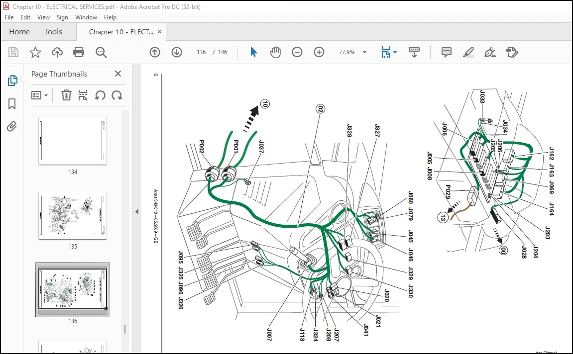
F3 – Implantation diagrams133
00 – Platform/Roll bar harness 5133
02 – Instrument panel harness – Mechanical reverser 6133
02 – Instrument panel harness – Shuttle reverser 7133
09 – Transmission harness – Mechanical reverser 8133
09 – Transmission harness – Shuttle reverser 9133
10 – Engine harness – 4 cylinders 10133
11 – 4 cylinder radiator cowling harness 11133
13 – Transmission control harness – Mechanical reverser 12133
13 – Transmission control harness – Shuttle reverser 13133
C4 – Positive – launch cableBattery – Starter 14133
C6 – Negative launch cable – Battery – Starter 15133
Notes146
F0_001_022_AXOS_PLF_0509_DIAGNOSTIC_GBpdf 0
Technical support user guide 3
F0 General 3
This section concerns all the coded elements contained in chapter F Each plate is first represented in 2D view with the list of relays and fuses The plates are then represented schematically in one or several views 3
F1 Function diagrams 3
Each diagram represents all devices, plates and their connections for a given use function, such as front lifting command or the fuel gauge (see below) 3
F2 Connector diagrams 4
This section lists all connectors, interconnections, and splices Each element has a matching list of path and wire numbers (see below) 4
F3 Implantation diagrams 4
This section allows to know the precise location of each electric element on board the vehicle 4
Contents 7
General 7
CLAAS COMPONENT NUMBERS (CCN) list 7 7
List of connectors 10 7
GENERAL WIRING 15 7
List of harnesses 16 7
List of grounding points 17 7
Fuse plates and electronic plates 18 7
CLAAS COMPONENT NUMBERS (CCN) list 9
List of connectors 12
GENERAL WIRING 17
List of harnesses 18
List of grounding points 19
Fuse plates and electronic plates 20
Fuse mount V21 20
PLEASE NOTE:
- This is the same manual used by the dealers to diagnose and troubleshoot your vehicle
- You will be directed to the download page as soon as the purchase is completed. The whole payment and downloading process will take anywhere between 2-5 minutes
- Need any other service / repair / parts manual, please feel free to contact [email protected] . We still have 50,000 manuals unlisted
S.M