CLAAS Tractor Nexos Elios 240-210 Technical Systems Manual – PFD DOWNLOAD
Original price was: $78.00.$27.95Current price is: $27.95.
CLAAS Tractor Nexos Elios 240-210 Technical Systems Manual – PFD DOWNLOAD
Description
CLAAS Tractor Nexos Elios 240-210 Technical Systems Manual – PFD DOWNLOAD
IMAGES PREVIEW OF THE MANUAL:
DESCRIPTION:
CLAAS Tractor Nexos Elios 240-210 Technical Systems Manual – PFD DOWNLOAD
Introduction
- Workshop manuals are subdivided into Parts and Sections, each characterized by a number, with its content specified in
the general summary. - Sections with mechanical content present the technical data, tightening torque sets, lists of tools, removal-refitting of
groups, revisions on bench, diagnostic and maintenance plans. - Sections or parts of the electrical/electronic systems describe the electrical network and electronic systems of the unit,
electrical diagrams, specifications of components, coding of components and diagnostic corresponding to the specific units
of the electrical system. - Section 1 describes the specifications of the engines, as well as their general operation.
Section 2 describes the type of fuel supply.
Section 3 concerns operating, and is divided into four separate parts:
1. Mechanical part dedicated to engine maintenance, limited to components differentiated according to specific use.
2. Electrical part related to wiring, electrical and electronic devices differentiated according to specific use.
3. Scheduled maintenance and specific revision.
4. Part of the diagnostic dedicated to those who, when providing technical support, must have simple and direct indications
to troubleshoot the main problems.
- Sections 4 and 5 concern overhaul operations of the engine fitted on the swivel cradle and the tools required for its
performance. - The appendix enumerates the general safety standards which everyone, whether the installers or handlers, must apply to
avoid severe accidents. - In its descriptions, the manual uses appropriate symbols to classify the information indicated. More particularly, we have
defined a series of symbols to classify remarks and another for support operations
TABLE OF CONTENTS:
CLAAS Tractor Nexos Elios 240-210 Technical Systems Manual – PFD DOWNLOAD
Chapter 00 – TOOLING 1
TOOLING 1
TOOLING PER CHAPTER 2
TOOLING PER REFERENCE 3
Chapter 01 – ENGINE – CRADLE 18
01 ENGINE – CRADLE 18
introduction 24
Introduction 25
Symbols 25
General notes 28
General notes on the electrical circuit 29
Grounding and shielding 30
Conversions between the main measurement units of the international system and current use derived magnitudes 31
General 32
Engine lubrication 33
Oil gas recycling 34
Cooling 35
Supercharging 36
Fuel supply 38
injection system 39
Injection pump 41
Supply pump 42
Fuel filter 43
Engine auxiliary devices 44
Removing / refitting engine auxiliary devices 45
Removing engine auxiliary devices 46
Refitting engine auxiliary devices 56
Removing / fitting the injection pump procedure 75
Location of the electrical components 80
Coolant temperature sensor 81
Water temperature sensor for KSB 81
Solenoid on the supply pump 81
Fuel filter 82
oil pressure switch 82
Engine speed sensor 82
Preheating resistor 83
Overhaul of the engine 84
General specifications 85
Fitting sets 86
Removing the connecting rods / pistons / crankshaft and camshafts 92
Repairing the cylinder block 95
Checks and measurements 95
Checking the bearing surface of the cylinder head and cylinder block 97
Timing 97
Camshaft 97
Checking cam lift and the bearing alignment 97
Bushes 98
Changing the bushes 98
Followers 99
Fitting the followers – Camshaft 99
Crankshaft101
Measuring the crank pins and journals101
Changing the oil pump command gear103
Fitting the crankshaft bearing bushings103
Measuring the gap between the crankshaft and journals103
Checking axial play of the crankshaft105
Rod – piston assembly105
Piston pins107
Conditions for proper pin – piston coupling107
Piston rings107
Connecting rod109
Bushes110
Fitting the connecting rod – piston assembly110
Fitting the piston rings111
Fitting the connecting rod – piston assemblies in the jackets112
Measuring the fitting gap of the connecting rod and crankshaft pin112
Piston protrusion check114
cylinder head114
Removing the valves114
Checking cylinder head sealing115
Checking the cylinder head bearing surface115
Valves116
Checking and resurfacing the valves116
Checking the valve stem valve guide gap and valve centering117
Valve guides117
Valve housing117
Valve springs119
Fitting the cylinder head119
Tightening torques121
Chapter 02 – Clutch clearance adjustment procedure124
CLAAS NECTIS – Clutch clearance adjustment procedure124
Chapter 02 – TRANSMISSION AND GEAR125
02 TRANSMISSION AND GEAR125
SAFETY INSTRUCTIONS131
General safety recommendations132
Safety symbols132
General precautions133
GENERAL INFORMATION141
Manual use142
Agreements and definitions142
General description145
Special recommendations146
GENERAL SPECIFICATIONS149
Technical Features150
Main Features150
Tightening torques, sealants and grease application152
Assembly typical data180
DISASSEMBLY AND ASSEMBLY193
4WD drop box194
Spring applied hydraulic released194
Mechanical control199
Final drive219
Final drive 1542 mm and 1242 mm219
Final drive 1542 mm and 1242 mm225
Final drive 972 mm229
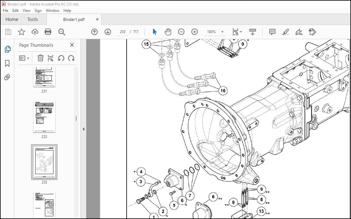
Teflon seals replacement (clutch shaft)233
Replacement234
Upper covers and rockshaft237
Disassembly237
Assembly238
Speed gears outer levers240
Disassembly240
Assembly241
Clutch housing243
12+12 Synchro shuttle243
24+24 Synchro shuttle – Synchro splitter246
24+24 Synchro shuttle – Power splitter250
Wet clutches255
Power splitter255
Synchro splitter266
Disassembly266
Assembly267
PTO270
HYDRAULIC control PTO cover and clutch271
Power take off296
HYDRAULIC control PTO input shaft309
Output shaft315
HYDRAULIC control PTO brake319
Ground Drive PTO331
MECHANICAL control GROUND DRIVE PTO shaft replacement337
PTO coupling group346
Slave cylinder348
Disassembly349
Actuator assembly353
Parking brake357
Disassembly358
Assembly365
Housing sensors assy371
Disassembly372
Assembly374
Differential locking control377
Disassembly377
Assembly377
Inner gear control assy382
Disassembly383
Assembly384
Idle gear392
Synchro shuttle392
Range gears (primary shaft)394
Disassembly396
Assembly397
Input shaft400
Synchro shuttle400
Synchro shuttle409
Disassembly409
Assembly412
Speed gears (primary shaft)414
Synchro shuttle414
Differential assy420
Disassembly420
Assembly421
Pinion – Ranges (secondary shaft)427
Disassembly427
Assembly428
Speed gears (secondary shaft)433
Disassembly433
Assembly434
End floats 1 and 2 determination437
Chapter 03 – CHASSIS – ELIOS 2 WHEEL DRIVE441
03 CHASSIS – ELIOS 2 WHEEL DRIVE441
GENERAL INFORMATION445
Manual use446
Agreements and definitions446
General description449
Recommendations for repair operations449
SAFETY INSTRUCTIONS451
General safety recommendations452
Safety symbols452
General precautions453
GENERAL SPECIFICATIONS455
General description456
Technical features456
Adhesive and sealant458
Tightening torques460
disassembly and assembly operations461
Steering cylinder group462
Disassembly462
Assembly464
Wheel hub group467
Disassembly468
Assembly469
Wheel hub support group472
Disassembly472
Assembly473
Axle beam group476
Disassembly476
Assembly478
Toe-in / steering angle480
Toe-in adjustment480
Steering angle adjustment482
03 CHASSIS – ELIOS 4 WHEEL DRIVE487
SAFETY INSTRUCTIONS491
General safety recommendations492
WARNING: before proceeding with any operations please read this chapter very carefully492
Safety symbols492
General precautions493
1 Operate always in a clean and dry environment493
2 Clean carefully the working environment and the machine before carry out the maintenance operations (Fig 5)493
3 Use only cleaning product in agreement with the regulations and always use them in the prescribed way494
4 Do not inhale chemical substances in dangerous concentration for the health care (Fig 6); ventilate the environments in which sprays and solvents, with volatile chemical substances, are used494
5 Wear suitable clothing and protection such as overalls, safety gloves and ear safety devices (Fig 7)494
WARNING: Safety goggles must always be worn while carrying out every assembling or disassembling operations (Fig 8)494
6 Use suitable ear protection, like ear plugs, to keep out noise and prevent injury to the ears A prolonged exposure to noise can damage your hearing494
7 The operator must be very careful with the equipment Do not use headphones to listen music while you are working on the product or on the group494
8 Do not wear slings, ties or other pending clothes Tie long hair behind the head and/or wear a protective cap494
9 Do not wear rings, armlets, necklaces or other metal objects that are dangerous when current is present494
10 Predispose always the first aid equipment in agreement with the working environments regulations, like the first aid kit (Fig 9)494
11 Keep the phone numbers of a doctor, an ambulance, a hospital and the fire department within reach near the telephone set (Fig 10) In case of accident it is indispensable to quickly ask for a medical intervention494
12 Keep your hands, feet and clothing away from moving parts of the tool machines Keep the safety distance from the machine, if it is moving, like during the testing operations (Fig 11)495
13 Light properly the working area by using devices in agreement with the safety regulations (Fig 12)495
14 During the maintenance operations it is strictly forbidden to light free flames (Fig 13) and smoking (Fig 14)495
15 Always be prepared for fires Keep the extinguisher within reach Before start any maintenance operation identify the extinguisher nearest to the working area and the prescribed fire regulations (Fig 15)495
16 The working environment must be always well aired by using devices in agreement with the safety regulations If local vents a495
GENERAL INFORMATION501
Manual use502
WARNING: CLAAS warranty does not cover every injury to personnel and damage to product caused by maintenance operations of not authorized personnel and/or by operations not in compliance with CLAAS safety regulations and prescribed procedures502
Agreements and definitions502
Note: The notes, pointed out externally to the text they refer, include important information502
WARNING: Warning indications point out the procedures, whose partial or complete non-observance can damage the machine or the connected equipment502
DANGER: Danger indications point out the procedures, whose partial or complete non-observance can injure the operator502
Note: do not follow carefully the CLAAS indications and/or current security regulations can causes serious damages to the persons or to the machines; these damages are not warranty covered504
Note: when this symbol is encountered, it is recommended to follow the described procedure as well as the section Special recommendations warnings504
Note: when this symbol is encountered, it is recommended to follow the described procedure as well as the section Special recommendations warnings504
Note: when this symbol is encountered, it is recommended to follow the described procedure as well as the section Special recommendations warnings504
Note: do not follow carefully the CLAAS indications can causes serious damages to the machine; these damages are not warranty covered504
Note: when this symbol is encountered, it is recommended to follow the described procedure as well as the section Special recommendations warnings504
General description505
Note: in case of replacement of one part of the bevel gear set this operation requires the replacement of the other part too505
Special recommendations505
WARNING: do not use a hammer directly on the seals506
WARNING: disposal of used oil must be done according to laws507
GENERAL SPECIFICATIONS509
General description510
Technical features511
Adhesives and tightening torques514
Note: apply only on indicated side514
Disassembly and Assembly517
Steering cylinder group518
Disassembly518
Assembly519
Epicyclic reduction gear group522
Disassembly522
Assembly524
Wheel hub group526
Disassembly526
Assembly530
Axle beam group535
Disassembly535
Assembly536
Trunnion bushes and seals538
Disassembly538
Assembly540
Differential support group544
Disassembly544
Assembly546
Bevel gear marking test552
Differential group553
Disassembly553
Assembly555
Pinion group557
Disassembly557
Assembly560
Toe-in / steering angle566
Toe-in adjustment566
Steering angle adjustment568
Chapter 06 – LIFTING DEVICE571
06 LIFTING DEVICE571
CONTENT573
FRONT LIFTING – NEXOS575
FRONT LIFTING – ELIOS578
REAR LIFTING581
SAFETY INSTRUCTIONS582
General safety recommendations583
Safety symbols583
General precautions584
GENERAL INFORMATION591
Manual use592
Agreements and definitions592
General description595
GENERAL SPECIFICATIONS596
General description597
Technical features598
Performances602
Maintenance603
Greasing points603
HYDRAULIC SYSTEM605
Hydraulic system606
Control valve607
Neutral phase607
Delivery phase609
Discharge phase611
Control valve sensitivity613
Adjustment of the control valve sensitivity613
Functioning of the control valve sensitivity614
MECHANICAL SYSTEMS616
Control levers617
Working of the internal leverage system617
Functioning with positioning control617
Use of control levers622
Adjustments624
Adjustment of the position control lever624
Adjustment of the draft control lever625
Checks626
Control of the reaction spring assembly626
Measurement check of the internal push bar627
Chapter 08 – POWER TAKE-OFF628
08 POWER TAKE-OFF628
CONTENTS630
FRONT POWER TAKE-OFF – NEXOS632
FRONT POWER TAKE-OFF – ELIOS634
Chapter 09 – HYDRAULIC SYSTEM636
09 HYDRAULIC SYSTEM636
CONTENT638
Hydraulic circuit639
Hydraulic circuit 2 pumps with mechanical distributors639
Legend640
Hydraulic circuit 3 pumps with mechanical distributors641
Legend642
Hydraulic circuit 3 pumps with electro hydraulic distributors643
Legend644
Mechanical transmission hydraulic circuit645
Legend646
Transmission hydraulic circuit with mechanical reverser and hydraulic doubler647
Legend648
Transmission hydraulic circuit with hydraulic reverser and hydraulic doubler649
Legend650
Chapter 10 – ELECTRIC SYSTEM651
10_Systeme electriquepdf651
10 ELECTRIC SYSTEM651
CONTENTS653
ERROR CODES655
INTRODUCTION656
ERROR CODES DISPLAY657
Description of the list of error codes658
Error code658
Transmitter module658
Designation658
List of error codes659
ELECTRIC DIAGRAMS668
CLAAS COMPONENT NUMBERS (CCN)669
Correspondence between the connectors and the CLAAS COMPONENT NUMBERS (CCN)672
W01 – MAIN HARNESS WITHOUT ELECTRO-DISTRIBUTORS677
W01 – MAIN HARNESS WITH ELECTRO-DISTRIBUTORS679
W02 – ENGINE HARNESS681
W03 – TRANSMISSION HARNESS682
W04 – VENTILATION AND A/C HARNESS684
W05 – LIGHTING HARNESS685
W06 – AIR BRAKE HARNESS686
W08 – A/C COMPRESSOR HARNESS687
W09 – PRIMARY HITCH OFFSET HARNESS688
W09_2 – SECONDARY HITCH OFFSET HARNESS689
W11 – REAR LIFTING SUPPLY HARNESS690
W11_2 – SECONDARY REAR LIFTING HARNESS691
W11_2 – PRIMARY REAR LIFTING HARNESS692
W11_4 – REAR COMMAND HARNESS OF REAR LIFTING693
W12 – SECONDARY HARNESS OF ELECTRO-DISTRIBUTORS694
W13 – MAIN HARNESS OF THE ELECTRO-DISTRIBUTORS695
Chapter 12 – CAB OPERATOR’S PLATFORM696
12 CAB / OPERATOR’S PLATFORM696
CONTENT698
REMOVE AND INSTALL CAB ROOF699
REMOVE AND INSTALL PLATFORM704
REMOVE AND INSTALL AIR CONDITIONING716
PLEASE NOTE:
- This is the same manual used by the dealers to diagnose and troubleshoot your vehicle
- You will be directed to the download page as soon as the purchase is completed. The whole payment and downloading process will take anywhere between 2-5 minutes
- Need any other service / repair / parts manual, please feel free to contact [email protected] . We still have 50,000 manuals unlisted
S.M