Claas Tractor Temis Technical System Manual – PDF DOWNLOAD
Original price was: $78.00.$30.95Current price is: $30.95.
Claas Tractor Temis Technical System Manual – PDF DOWNLOAD
Description
Claas Tractor Temis Technical System Manual – PDF DOWNLOAD
IMAGES OF MANUAL:
DESCRIPTION:
Claas Tractor Temis Technical System Manual – PDF DOWNLOAD
2) Operation
The cooling circuit consists of the radiator, the water
pump (A) and the thermostat (I).
The cooling fluid is propelled by the water pump to the
cooling fluid passage adapter (B) and flows around the
oil cooler plates (D). From the oil cooler, the fluid is
directed towards the main cooling gallery (E). On
leaving the gallery, the cooling fluid circulates in the
cooling jacket (F), around the cylinder liners, towards
the passages in the top part of the block (G) and the
cylinder head. In the cylinder head, the cooling fluid
circulates in the passages (H) around the inlet and
exhaust ports, the valve seats and the injectors. The
cooling fluid flows towards the front of the cylinder
head and exits via the water manifold/thermostat unit
During warm-up, the thermostat (I) is closed and
the cooling fluid is directed towards the suction side
of the water pump by a bypass circuit (L). The
cooling fluid continues circulating in the cylinderblock,
the cylinder head and the water pump,
providing rapid and uniform warm-up.
When the engine reaches its operating temperature,
the thermostat opens and allows the cooling fluid to
pass through the radiator top hose to reach the
radiator top reservoir (M). The cooling fluid circulates
in the radiator, dissipating its heat, then leaves the
radiator via the bottom hose and enters the water pump
from the suction side (O). The cooling fluid continues
to circulate around the engine and the radiator until the
temperature of the cooling fluid falls below the thermostat
opening temperature.
TABLE OF CONTENTS:
Claas Tractor Temis Technical System Manual – PDF DOWNLOAD
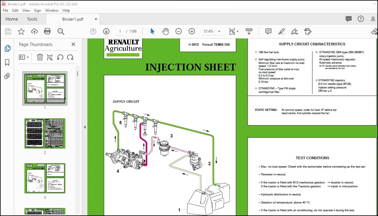
Chapter A0 – INJECTION SHEET 1
INJECTION SHEET 1
TEMIS 550 1
TEMIS 610 3
TEMIS 630 5
TEMIS 650 7
Chapter A1-1 – INJECTION SUPPLY H 3912 RENAULT TEMIS 550 ( DPS 4045 TRT 52 ENGINE) 9
DPS Injection supply 9
Contents 10
Identification 13
Section drawings 15
Specifications 17
Tightening torques 19
Operating principles 21
Checks-Adjustments 27
Removal-Installation 37
Adjustment of controls 43
Tools 45
Chapter A1-2 – INJECTION SUPPLY H 3922 TEMIS 610 (IVECO engine), H 3932 TEMIS 630 (IVECO engine), H 3942 TEMIS 650 (IVECO engine) 47
IVECO INJECTION SUPPLY 47
Contents 49
Identification 51
Section drawings 53
Specifications 57
Tightening torques 59
Operating principle 61
Checks-Adjustments 69
Removal-Installation 73
Adjustment of controls 81
Tools 83
Chapter A2-1 – DPS ENGINE 87
DPS Engine 87
Contents 89
Identification 93
Cross sections 95
General specifications 97
Dimensional specifications 99
Tightening torques 107
Operating principle 113
Checks-Adjustments 121
Disassembly-Assembly 125
Tools 169
Chapter A2-2 – IVECO ENGINES H 3922 TEMIS 610, H 3932 TEMIS 630, H 3942 TEMIS 650 178
IVECO Engines 178
Contents 180
Identification 182
Section drawings 186
Specifications 190
Tightening torques 202
Operating principle 208
Checks-Adjustments 216
Disassembly-assembly 220
Tools 264
Chapter B1 – CLUTCH LUK DT 355 – 330, LUK DT 330 – 310, LUK DT 310 – 310, LUK DT 350 (TRACTONIC) 268
Clutch 268
Contents 270
Specifications 272
Access to units 282
Displacement and PTO clutches 286
PTO clutch TRACTONIC 298
Clutch stops and guide 304
Displacement clutch control 308
PTO power-assisted clutch 312
Tools 318
Chapter B2 – GEARBOXES B13-29 – 2 X 4 – REVERSER, B13-25 – 4 X 4 – REVERSER, B13-35 – 24 X 8 – TRACTONIC 322
Gearboxes 322
Contents 324
General specifications 330
Transmission assembly 338
Access to units 362
Gearbox casings 366
Selector rails and forks 372
PTO clutch shaft 392
B13-29 gearbox 402
B13-25 gearbox 416
B13-35 gearbox 428
Primary shaft 470
Secondary shaft 480
Front intermediate shaft 492
Rear intermediate shaft 496
PTO shafts 502
Tools 516
Chapter B3 – LOW PRESSURE HYDRAULIC SYSTEM 524
LOW PRESSURE
HYDRAULIC SYSTEM 524
Contents 526
Specifications 528
Presentation 530
Checks 548
Tools 552
Chapter C1 – REAR AXLE P09A – P25 554
Rear Axle P09A-P25 554
Contents 556
Specifications 558
Presentation 562
Access-removal/installation of the housing assy 568
PTO extension shaft 570
Differential shafts 574
Differential and crownwheel 578
Trumpet housings and wheel shafts 588
Differential locking control 598
Tools 608
Chapter C2 – OIL BATH DISC BRAKES HRE 5 224 HRE 4 224 612
Oil bath disc brakes 612
Contents 614
Specifications 616
Service brakes-handbrake 620
Hydrostatic control 636
Tools 644
Chapter C3 – 4-WHEEL DRIVE UNIT 646
4 Wheel drive unit 646
Contents 648
4 Wheel drive unit 650
Tools 666
Chapter D – FRONT AXLE A 86-3 (2019) TEMIS 550-610, A 88-4 (2029) TEMIS 630-650 670
Front axle A86-3 and A88-4 670
Contents 672
Specifications 674
Bevel gear differential 675
Tightening torques 676
Drive transmission 677
Servicing 678
Prelimitary disassembly prior to maintenace 682
Steering cylinders and link rods 683
Removal-installation 684
Universal joint 688
Differential 689
Bevel gear and crown gear 690
Tools 696
Chapter E – HYDRAULICS 700
Hydraulics 700
Contents 702
Hydraulics 706
Brake valve 722
Hydraulic manifold 736
Auxiliary distributor 750
Main distributor (mechanical lift) 768
Main distributor (REXROTH SIGMA) 806
Steering unit 836
Valve (OLSA) 868
Troubleshooting sheet 878
Hydraulic lift 886
Chapter F – ELECTRICS 904
Electrics 904
Contents 905
Wiring and general lists 906
Diagrams and functions 908
Harness connections and links 970
Cable routing1040
Miscellaneous1056
Tools1058
Chapter G1 – INSTRUMENT PANEL1060
Instrument panel1060
Contents1062
General-functions provided1064
Description1065
Acces to bulbs1067
Operation1071
Removal-Installation of connectors1077
Connection and functions of wires1077
Configuration1079
Chapter G2 – ELECTRONIC TRACTO CONTROL UNIT1082
Electronic Tracto control unit1082
Contents1084
General arrangement1088
Control panel1089
TCE4 lift unit1090
Chapter G3 – TRACTONIC ELECTRONIC CONTROL UNIT1100
Tractonic electronic control unit1100
Contents1102
General1104
Sensors, user controls, wiring1108
Functions1134
METADIAG application1140
Tools1152
Chapter G4 – INFOTRAC ON-BOARD COMPUTER1156
Infotrac on-board computer1156
Contents1158
Functions provided-description1160
Operation1161
Removal-installation of the unit1165
Connection and functions1166
Calibration1167
Sensors1169
Layout1170
Chapter H1 – CAB1172
Cab1172
Contents1174
Removal of complete cab1176
Lifting the cab for TEMIS X1180
Lifting the cab for TEMIS Z1184
Tools1188
Contents1189
MR 328 EN1189
PLEASE NOTE:
- This is the SAME MANUAL used by dealerships to diagnose your vehicle
- No waiting for couriers/posts as this is a PDF manual and you can download it within 2 minutes once you complete the payment.
- Your payment is secure and delivery of the manual is INSTANT – You will be redirected to the DOWNLOAD PAGE.
- So do not hesitate and write to us for any questions you may have: heydownloadss @gmail.com
S.M.