Claas Tractor Xerion Operator’s Manual – PDF DOWNLOAD
Original price was: $86.95.$28.95Current price is: $28.95.
Claas Tractor Xerion Operator’s Manual – PDF DOWNLOAD
Description
Claas Tractor Xerion Operator’s Manual – PDF DOWNLOAD
DESCRIPTION:
Claas Tractor Xerion Operator’s Manual – PDF DOWNLOAD
INTRODUCTION :
The present Operator’s Manual is primarily intended for the machine operator and contains information about using, setting, operating and maintaining the XERION. Provided all instructions regarding maintenance and care are followed, you can count on many years of reliable service.
- The Operator’s Manual describes different machine equipment versions. The order confirmation form contains the equipment version of your machine.
- If you have ordered equipment which is not described in this Operator’s Manual or for which the general sense of the text does not apply, please have our service department or the authorised dealer instruct you before putting the equipment into operation.
- Please have your authorised CLAAS dealer carry out the recommended regular inspections. Neglecting regular maintenance and improper machine operation results in reduced performance and loss of time. When properly operated and carefully maintained, your vehicle will always perform well.
TABLE OF CONTENTS:
Claas Tractor Xerion Operator’s Manual – PDF DOWNLOAD
1 Introduction
Introduction 1 1 1
2 Contents
Contents 2 1 1
3 General information
Road traffic 3 1 1
Instructions for extension devices 3 1 2
Instructions for extension devices 3 1 2
Instructions for hooked-up lof work machines 3 1 7
Wording of the leaflet 3 1 7
Important information 3 2 1
Number plate / serial number 3 3 1
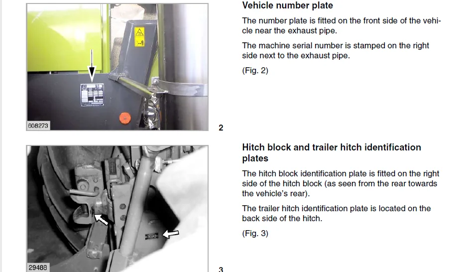
Vehicle number plate 3 3 2
Hitch block and trailer hitch identification plates 3 3 2
Engine identification plates 3 3 2
Transmission identification plate 3 3 3
4 Safety rules
Safety rules 4 1 1
Battery isolating switch 4 1 4
Wheel chocks 4 1 4
Applying the wheel chocks 4 1 4
Grab handles 4 1 4
Safety decals with pictorials 4 2 1
5 Specifications
CLAAS XERION 5 1 1
Engine 5 1 1
Cooling system 5 1 1
Electric system 5 1 1
Fuel tank 5 1 1
Tilted vehicle position 5 1 1
Drive 5 1 1
Transmission 5 1 1
Driven steering axles 5 1 1
Steering 5 1 1
Brakes 5 1 2
Hydraulic system 5 1 2
Main circuit
(power lift, additional control units) 5 1 2
Steering circuit
(Oil cooling, steering, brake) 5 1 2
Emergency circuit (emergency steering) 5 1 2
P t o shafts 5 1 2
Tail p t o shaft 5 1 2
Hitches 5 1 3
Power lifts 5 1 3
Front power lift 5 1 3
Tail power lift 5 1 3
CLAAS XERION 5 1 4
Additional control units for operating
vehicle-mounted implements 5 1 4
Electrical supply and control of
vehicle-mounted implements 5 1 4
Socket, 56-pin 5 1 4
Signal socket (ISO), 7-pin 5 1 4
Signal socket (ISO), 9-pin 5 1 4
Unit socket (ISO), 9-pin 5 1 4
Socket(s), 3-pin 5 1 5
Sockets, 7-pin 5 1 5
Tightening torques 5 1 5
Driven steering axles 5 1 5
6 Prior to operation
Cab 6 1 1
Roof console – overview 6 1 1
Air conditioner 6 1 3
Operating and display elements 6 1 3
Putting the automatic air conditioner control into
operation 6 1 4
Setting the cab temperature 6 1 5
Manually setting the evaporator blower speed 6 1 5
Activating ECON mode 6 1 6
Deactivating ECON mode 6 1 6
REHEAT operation
(Demisting cab windows) 6 1 7
Displaying the outside temperature 6 1 8
Changing the temperature display to °Fahrenheit 6 1 8
Heating the leg area 6 1 8
Temperature sensor F0 fault indicator (room, blue) 6 1 9
Temperature sensor F1 fault indicator (blow-out, yellow) 6 1 9
Temperature sensor F2 fault indicator (outside, red) 6 1 9
Adjusting the mirror 6 1 10
Adjusting the external mirrors 6 1 10
Adjusting the side view mirror 6 1 11
Adjusting the lighting 6 1 11
Road travel with lighting 6 1 11
Working with lighting 6 1 12
Warning plates 6 1 13
Lighting with the cab in rear 6 1 13
Roll-up sun screens 6 1 14
Switch console 6 1 15
Adjusting the operator’s seat 6 1 16
Steering column 6 1 20
Adjusting the steering column 6 1 20
Vehicle information unit 6 1 20
Multi-function switch 6 1 21
Multi-function handle 6 1 22
Windscreen washer 6 1 23
Central terminal compartment 6 2 1
Fuses F 6 2 2
Tyres 6 3 1
Mud guard on floating axle 6 3 1
Adapting the mud guard: 6 3 1
Mud guard positions 6 3 2
Selecting implement combinations 6 4 1
Application example
Ordered combination on the rear three-point hitch 6 4 4
Weights 6 5 1
Tail weights 6 5 1
Centre weights 6 5 2
Contents
2 1 2 BA XERION – 0293 208 1
Contents
7 Operation
Driving the xerion 7 1 1
Starting the engine 7 1 1
Selecting the transmission mode 7 1 2
Automotive mode 7 1 2
Manual mode 7 1 2
Driving the Xerion 7 1 3
Before driving off 7 1 3
During travel 7 1 3
Road travel 7 1 4
Driving in automotive mode 7 1 4
Driving with the parking brake on 7 1 5
Driving off in manual mode 7 1 5
Pushing operation 7 1 7
Driving ranges 7 1 8
Changing the driving range 7 1 8
Changing the direction of travel 7 1 9
Selecting the direction of travel at vehicle standstill 7 1 9
Changing the direction of travel while driving 7 1 10
Cruise control 7 1 11
Storing cruise control values 7 1 11
Activating cruise control values 7 1 12
Changing cruise control values 7 1 13
Deactivating the cruise control 7 1 14
Adjusting the engine speed 7 1 15
Adjusting the minimum engine speed 7 1 15
Storing the fixed engine speed 7 1 16
Activating/changing the fixed engine speed 7 1 17
Engaging / disengaging the differential locks 7 1 18
Engaging the centre differential lock 7 1 18
Engaging the centre differential lock and the axle locks 7 1 19
Releasing the differential locks manually 7 1 19
Automatic differential lock monitoring device 7 1 20
Switching the transmission to neutral 7 1 20
Brakes 7 1 21
Foot brake 7 1 21
Parking brake 7 1 22
Inching pedal 7 1 23
Parking the Xerion 7 1 24
Limp Home 7 1 25
Towing the Xerion 7 1 27
Towing with the engine running and steering and
brake hydraulics in working order 7 1 27
Towing with the engine standing still 7 1 27
Cab positions 7 2 1
Engine position 7 2 1
Centre position 7 2 1
Tail position 7 2 1
Rotating the cab 7 2 2
Steering with cab in rear position 7 2 3
8 CEBIS Operation
9 Operation of vehicle-mounted implements
Connecting / disconnecting vehicle-mounted implements 9 1 1
Front power lift – overview 9 1 2
Before connecting front implements 9 1 2
Connecting the front implements in a
height-variable / rigid manner 9 1 2
Adjusting the lifting force and the lifting path 9 1 3
External operation of front power lift 9 1 3
Connecting implements to the front power lift 9 1 4
Adjusting and connecting the front upper link 9 1 6
Disconnecting the front implement 9 1 6
Use without front power lift 9 1 7
Tail power lift – overview 9 1 7
External operation of tail power lift 9 1 7
Connecting implements to the tail power lift 9 1 8
Adjusting and connecting the tail upper link 9 1 10
Disconnecting the tail implement 9 1 11
Adjusting the lower link clearance 9 1 11
Changing the lifting angle of the implement 9 1 12
Adjusting the lift brace length 9 1 12
Adjusting the lower links to variable height 9 1 12
Adjusting the lower link to a rigid position 9 1 13
Adjusting the lower link to lateral float
position or rigid position 9 1 13
Adjusting the lower link to be laterally rigid 9 1 13
Adjusting the automatic mode 9 1 13
Vehicle-mounted implements 9 2 1
Removing / installing the exhaust tailpipe 9 2 1
Removing the exhaust tailpipe 9 2 1
Installing the exhaust tailpipe 9 2 1
Floating axle lock 9 2 2
Installing the universal drive shafts 9 3 1
Replacing the stub of p t o shaft 9 3 2
Installing the universal drive shafts 9 3 3
Connecting implements to the hydraulic system 9 4 1
Front hydraulic ports 9 4 2
Tail hydraulic ports 9 4 2
Load Sensing 9 4 2
White hydraulic ports 9 4 3
Connecting an external consumer to a white
hydraulic port 9 4 3
Disconnecting the hydraulic hoses 9 4 3
Hitches 9 5 1
Trailer hitch 9 5 1
Adjusting the trailer hitch position 9 5 1
Removing the trailer hitch 9 5 1
Connecting implements to the trailer hitch 9 5 2
Unhitching implements from the trailer hitch 9 5 2
Ball-type hitch 9 5 3
Installing the ball-type hitch 9 5 3
Connecting implements to the ball-type hitch 9 5 4
Disconnecting implements from the ball-type hitch 9 5 4
Swinging drawbar 9 5 5
Short / long swinging drawbar 9 5 5
Swinging drawbar with trailer hitch ball 9 5 5
Hitch block with Piton Fix 9 5 6
Hitch block with ball 9 5 6
Special hitch with ball 9 5 7
Connecting semi-trailers / implements 9 5 7
Central lubrication system 9 6 1
Checking the level 9 6 1
Filling the grease container 9 6 1
Allowed types of grease 9 6 2
Function testing 9 6 2
0293 208 1 – BA XERION 2 1 3
Contents
Problems and remedies – Central lubrication system 9 6 3
Trailer brake connections 9 7 1
Before connecting the trailer brake system 9 7 1
Connecting the trailer to the compressed air
brake system 9 7 1
Putting the trailer compressed-air brake into operation 9 7 2
Connecting the trailer to the hydraulic brake system 9 7 2
Sockets 9 8 1
Lighting according to StVZO (German Regulations
Authorizing the Use of Vehicles for Road Traffic) 9 8 1
Power supply of controls and displays 9 8 1
Autopilot sensor 9 8 2
Socket for vehicle-mounted implements 9 8 2
Signal transmission to controls and displays 9 8 3
Installation of electric and electronic devices 9 9 1
Installation of mobile communication systems 9 9 1
Installing additional controls/displays 9 9 2
Putting the p t o shaft / auxiliary
power take-off into operation 9 10 1
Engaging the tail p t o shaft 9 10 2
External operation of tail p t o shaft 9 10 3
Auxiliary power take-off 9 10 4
Engaging the auxiliary power take-off 9 10 4
Operating the power lift 9 11 1
Front power lift 9 11 1
Operating the front power lift 9 11 1
Tail power lift 9 11 2
Adjusting the tail power lift working position 9 11 2
Operating the electronic lift control 9 11 2
Road travel with vehicle-mounted implements 9 12 1
Pitching dampening 9 12 2
Activating the pitching dampening 9 12 2
Operating hydraulic vehicle-mounted implements 9 13 1
White hydraulic port 9 13 1
Red / yellow / green hydraulic port 9 13 2
Raising an implement 9 13 3
Lowering an implement 9 13 3
Blue hydraulic port 9 13 3
Configuring the hydraulic ports 9 13 4
10 Maintenance
Important maintenance instructions 10 1 1
Important maintenance instructions and safety rules 10 1 1
Maintenance schedules and lubricants charts 10 2 1
Maintenance schedule 10 2 1
Lubricants chart 10 2 3
Hydraulic system 10 3 1
Checking the hydraulic oil level 10 3 1
Changing the hydraulic oil 10 3 2
Topping up hydraulic oil 10 3 2
Replacing the hydraulic oil filter 10 3 2
Replacing the return flow filter 10 3 2
Replacing the pressure filter 10 3 3
Replacing the suction filter 10 3 4
Replacing the venting filter 10 3 5
Draining the leakage oil collecting container 10 3 5
Leakage oil collecting container Tail hydraulic ports 10 3 5
Leakage oil collecting container Front hydraulic ports 10 3 6
Transmission 10 4 1
Main transmission 10 4 1
Checking transmission oil level 10 4 1
Changing the transmission oil 10 4 2
Topping up transmission oil 10 4 2
Replacing the transmission oil fine filter 10 4 2
P t o gearboxes 10 4 3
Checking the p t o gearboxes oil level 10 4 3
Changing the p t o gearbox oil 10 4 3
Topping up p t o gearbox oil 10 4 3
Brakes / compressed air brake system 10 5 1
Draining the accumulator 10 5 1
Checking the parking brake air gap 10 5 1
Releasing the parking brake 10 5 1
Checking the antifreeze agent level 10 5 2
Switching off the antifreeze pump 10 5 2
Axles 10 6 1
Check planetary gear oil level 10 6 1
Changing the planetary gears oil 10 6 2
Checking the differential oil level 10 6 2
Changing the differential oil 10 6 3
Cleaning the venting valves 10 6 3
Checking the track adjustment 10 6 4
Checking the kingpin bearings for absence of play 10 6 4
Air conditioner 10 7 1
Cleaning the condenser 10 7 1
Checking the refrigerant level 10 7 1
Checking the moisture saturation of the filter
receiver drier 10 7 2
Cab 10 8 1
Cleaning / replacing the cab filters 10 8 1
Cleaning the units located in the cab roof 10 8 1
Checking the windscreen washer 10 8 2
Lift tower 10 9 1
Check oil level in lift tower planetary gear 10 9 1
Change oil in lift tower planetary gear 10 9 1
Topping up oil in the lift tower planetary gear 10 9 1
Hitches 10 10 1
Ball-type hitches 10 10 1
Checking the ball-type hitch for wear 10 10 1
Checking the special hitch with ball for wear 10 10 1
Adjusting the height play of the ball-type hitch 10 10 2
11 Maintenance – Engine
Important maintenance instructions 11 1 1
Important maintenance instructions and safety rules 11 1 1
Warranty on non-genuine CATERPILLAR products 11 1 2
Maintenance schedules and lubricants charts 11 2 1
Maintenance schedule 11 2 1
Lubricants chart 11 2 2
Engine overview 11 3 1
CATERPILLAR C9 11 3 1
Fuel system 11 4 1
Filling the fuel tank 11 4 1
Checking the water separator / draining water 11 4 1
Replacing the fuel pre-filter cartridge 11 4 2
Fuel filter 11 4 3
Replacing the fuel filter cartridge 11 4 3
Venting the fuel system 11 4 4
2 1 4 BA XERION – 0293 208 1
Contents
Engine oil 11 5 1
Checking the engine oil level 11 5 1
Draining the engine oil 11 5 2
Changing the engine oil filter 11 5 2
Topping up engine oil 11 5 3
Cooling system 11 6 1
Coolant 11 6 1
Checking the coolant level 11 6 1
Changing the coolant 11 6 2
Topping up coolant 11 6 3
Radiator 11 6 4
Cleaning the radiator unit 11 6 4
Cleaning the cooling air suction screen 11 6 4
Air-intake system 11 7 1
Air-intake system 11 7 1
Checking air-intake screen for dirt 11 7 1
Check air-intake hose for damage 11 7 1
Checking the mounting clamps of the charge-air pipes 11 7 2
Dry-type air filter 11 7 3
Cleaning the air filter 11 7 3
Replacing the air filter safety cartridge 11 7 6
V-belts / valves 11 8 1
Fan / alternator drive belt 11 8 1
Checking the drive belt condition 11 8 1
Electric system 11 9 1
Batteries 11 9 1
Battery isolating switch 11 9 1
Alternator 11 9 2
12 Lubrication chart
Lubricants and notes 12 1 1
13 Index
Index 13 1 1
IMAGES PREVIEW OF THE MANUAL:
CLAAS TRACTOR XERION OPERATOR’S MANUAL – PDF DOWNLOAD:
PLEASE NOTE:
- This is the SAME manual used by the dealers to troubleshoot any faults in your vehicle. This can be yours in 2 minutes after the payment is made.
- Contact us at [email protected] should you have any queries before your purchase or that you need any other service / repair / parts operators manual.
S.V