Claas Xerion 2500 Xerion Operator’s Manual – PDF DOWNLOAD
Original price was: $78.00.$24.95Current price is: $24.95.
Claas Xerion 2500 Xerion Operator’s Manual – PDF DOWNLOAD
Description
Claas Xerion 2500 Xerion Operator’s Manual – PDF DOWNLOAD
DESCRIPTION:
Claas Xerion 2500 Xerion Operator’s Manual – PDF DOWNLOAD
Introduction
- This operator’s manual applies to the prime mover XERION 2500 and is primarily intended to give the machine operator information on setting, using and servicing the machine. Provided you follow the advice on the care and servicing of your machine, you will be rewarded with reliable and long service from your prime mover.
- The Operator’s Manual describes possible configurations of the machine. Please obtain information on the configuration of your machine from your confirmation of order.
- In case you have ordered equipment and/or accessories which are not described in this Manual or to which the descriptions in this manual do not apply you should request the instructions for using such equipment from our Service Department or from your authorised dealer before you start operating it.
- We recommend that you allow your authorized CLAAS Dealer to carry out the regular maintenance. Omissions of parts of the maintenance schedule or incorrect operation lead to a drop in performance and cost valuable time. By correctly servicing and operating your prime mover you can ensure that it always operates reliably.
TABLE OF CONTENTS:
Claas Xerion 2500 Xerion Operator’s Manual – PDF DOWNLOAD
Contents
Important 17
Identification plates 19
Prime mover identification plate 19
Engine identification plate 19
Hitch support frame and hitch identification plates 19
Safety rules 20
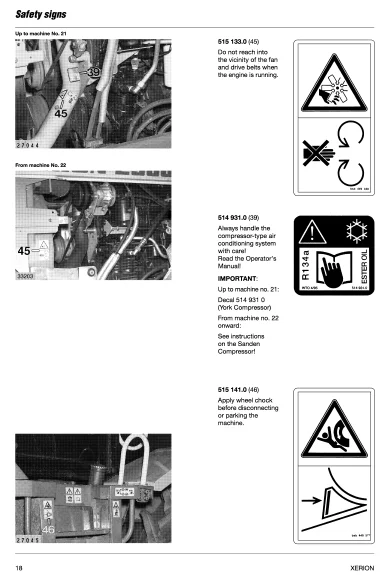
Safety decals with pictorials 23
1 Technical Data
2 Prior to operation
Operator station 2 3
Roof console 2 4
Adjusting outside mirror 2 4
Adjusting th e ventilation louvres 2 5
Adjusting the air conditioning system 2 5
Adjusting the heater 2 6
Sunblinds (Extra) 2 6
Set lighting 2 7
Travel on road with lighting 2 7
Warning plates 2 8
Work with lighting 2 8
Control panel 210
Instrument monitor 211
Adjusting the steering column 213
Adjusting the operator’s seat 214
Vehicle information unit 216
Multi-function switch 216
Multi-function handle on control and steering lever 216
Wheel chocks 217
Tyres 217
Steering stops 217
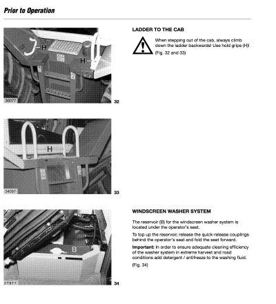
Ladder to the cab 218
Windscreen washer system 218
Central electric switch and fuse box 219
3 Operation
Start XERION 3 3
Start the engine 3 3
Select start-off gear 3 3
Select a gear strategy 3 4
Drive lever 3 4
Power 3 5
Accelerator pedal 3 5
Constant 3 5
Hand throttle function 3 6
Activating hand throttle 3 6
The inching pedal 3 7
s elect steering strategy 3 8
Steering the front axle 3 9
Steering the rear axle 3 9
Activating four wheel steering 3 9
Steering both axles/ Crab steering 3 9
Driving the XERION 310
Unlocking drive lever 310
Selecting direction of travel 311
Automatic disengagement of gears 311
Service brake 311
Parking brake 312
Engaging the differential lock 312
Use of the Autopilot 313
Connecting the transmitter 313
Activating the Autopilot 314
Centralizer 314
Overrider switch 314
Seat contact 314
De-activating the Autopilot 315
Driving on the road 315
Parking XERION 315
Go-HOME Control 316
Operating the Go-HOME Control 316
Change of cab position 318
Position “cab central” 319
Position “rear centre” 319
Position “rear lateral” 319
Swivelling the cab from position “cab central” to
position “rear central/ lateral” 320
Moving the cab from position “rear centre /
lateral” to position “cab central” 320
Changing the position of the pivot post 321
4 Operation – mounted / attached imnplements
Coupling and uncoupling of attached instruments 4 3
Components of the front power lift 4 3
Connecting implements to the front power lift 4 3
Attaching the implement 4 4
Adjusting the length of the upper link and to
connect the upper link 4 5
Removing the implement 4 5
Components of the rear power lift 4 6
Connecting the implements to the rear power lift 4 6
Adjusting the length of upper link and
connecting the upper link 4 8
Uncoupling the implement 4 8
Adjusting the distance between the lower links 4 9
Changing the kick-up angle of the implement 4 9
Adjusting the length of the lift rods 410
Providing the lower links with a degree
of vertical float 410
Setting for rigid lower links 411
Setting for lateral float or rigid position 411
Mounted implements 412
Oscillating axle lock 412
Activating the oscillating axle lock 412
De-activating the oscillating axle lock 413
Attaching universal drive shafts 414
Fitting universal drive shafts 414
Connecting implements to the hydraulic system 416
Hydraulic connections, front 417
Hydrrauli c connections, rear 417
L oad sensing 418
Hydraulic connectors with non return valve 418
Priority arrangement – red hydraulic connectors 418
Blue hydraulic connectors 419
Removing hydraulic hoses 419
Hitches 420
Trailer coupling 420
Moving trailer coupling 420
Coupling trailers and trailed implements 421
Uncoupling trailers and trailed implements 421
Swinging Drawbar 421
Piton-fix 422
Trailer brake connections 423
Connecting trailer to the hydraulic brake system 423
Connecting trailer to the brake system 423
Electric power supply to trailers and implements 424
5
Fitting additional controls and/or indicators 425
Operating attached and mounted implements 426
Using the PTO 426
Displaying PTO speed 426
Adjusting PTO speed 427
Engaging PTO 427
Operating the power lift 428
Operating the front power lift 428
Operating the rear power lift 428
Unlocking EHR D (electronic lift control) 429
Defect diagnostic functions 429
Setting preadjustments 430
Setting the mix between positioning and
traction force 430
External controls 430
To set lowering speed 430
To set transport height 431
To pre-select pressure or slip control 431
Activating the pressure control 431
Activating slip control 432
To set target value 433
Using the touch keys on the multi-function
handle 433
To raise rear power lift to pre-set transport
height 434
To lower rear power lift to pre-set working
depth 434
To raise rear power lift 434
To lower rear power lift 434
External controls 435
Front power lift 435
Rear power lift 435
Driving on public roads with attached
implements 436
Damping of vibrations 436
To activate vibration damping 436
Setting the threshold speed at which the
damping starts to operate 437
Operating hydraulically powered mounted or
attached implements 438
Setting hydraulic flow rate 439
Setting flow throttle flow for all hydraulic
connectors 439
Additional control panels 440
5 Operation XIMO – Xerion instrument monitor
Monitor: Keys, switches, displays 5 4
XIMO instrument monitor 5 6
Prior to initial installation 5 7
Rotary switch D 5 8
Machine and system settings by the instrument
monitor XIMO 5 9
Adjustments 511
Selecting the national language 511
Setting the clock 511
“Learn” power lift end stops 513
Front power lift end stops 513
Rear power lift end stops 513
Calibrate tachometer 515
Calibration run output 515
Impulses 100 m output 515
Guide for impulses 100 m 515
Setting the radar sensor 517
Define type of radar sensor 517
Define permissible slip 517
Calibrate radar sensor 519
Calibration run Radar 519
Impulses 100 m radar 519
Save wheel position 521
Front wheel position 521
Rear wheel position 521
Define working position 523
Working position, front 523
Working position, rear 523
Defining the type of area calculation 525
Selecting measuring unit 525
Setting the working width 527
Setting the partial width 527
Saving/loading/displaying implement data 529
CLAAS implement settings 529
Display settings 529
Load adjustments 529
Freely selectable implement adjustments 531
Display settings 531
Load settings 531
Save settings 531
Recording 533
Type of area calculation / manual area counting 533
Daily recorder 533
Display current area work rate 535
Display engine RPM 535
Display operating hours 535
Maintenance 535
Display service intervals 535
Reset service intervals 535
6 Faults and remedies
Alarms and fault messages on the information monitor 6 3
Fault, cause and remedy 6 4
Emergency handcontrol of attached /
mounted implements 6 7
Fuses and relays 6 8
7 Maintenance
Important maintenance instructions 7 2
Maintenance chart 7 4
Filling volumes 7 6
T o open protective covering 7 7
Front grill 7 7
Side covers 7 8
Compressor-type air conditioning system 7 9
Tension compressor drive belt 7 9
Clean condenser 7 9
Check refrigerant level 710
Check moisture saturation of the filter-drier 710
HM8 li ransmission 710
Check transmission oil level 711
Topping up with small quantities of oil 712
Change transmission oil 712
Filling gearboxes with oil 712
Replace oil filter 713
Hydraulics and steering 714
Check instrument monitor for warning displays 714
Check oil level in hydraulic oil reservoir 714
Change hydraulic oil 715
Top up hydraulic oil 715
Replace 10 μm oil filter 716
Replace 60 μm oil filter 716
Cab 717
6
Clean/replace filters 717
Check windscreen washer 717
Rigid and oscillating axle 718
Check oil level of planetary final drives 718
Change oil of planetary final drives 718
Check oil level in differentials 719
Change oil of differentials 720
Clean breather valves 721
Check track width 721
Adjust track width 722
Check backlash of king pin bearings 722
Have wear and leaks of multi-disc brakes checked
and brake discs replaced 722
Front PTO 722
Adjust drive pulley 723
Pivot post 723
Check oil level in planetary gearbox 723
Change oil 723
Top up oil 723
Retighten mounting bolts of swivelling drive 723
Brakes/air brake system 724
Check brake fluid level of service brake 724
Drain the pressure tank 724
Check operating clearance of parking brake 725
Check anti-freeze level 725
Switch off anti-freeze pump 725
8 Lubrication Chart
Battery isolating switch 921
Electrolyte level and electrolyte concentration 922
9 Maintenance – Engine
Important maintenance instructions 9 3
Engine maintenance schedule 9 4
Engine lubricants chart 9 5
Engine views 9 6
Fuel system 9 7
Filling the fuel tank 9 7
Replacing the fuel filter canister and the fuel filter
screen 9 7
Bleeding the fuel system 9 8
Draining water from fuel tank 9 9
Clean fuel prefilter in the water separator 9 9
Engine oil 910
Checking the engine oil level 910
Changing engine oil and oil filters 910
Draining the engine oil 910
Changing the lubricating oil filter 911
Pouring in lubricating oil 911
Checking the fan / alternator drive belt 912
Cooling system 913
Checking coolant level 913
Checking coolant temperature 913
Topping coolant 914
Draining coolant 914
Renewing the coolant filter canister 915
Cleaning the radiator housing/ radiator 917
T o clean the radiator air intake screen 917
Dry-type air filter 918
To clean the main cartridge 918
Removing the main air filter cartridge 918
Installing the main air filter cartridge 919
Renewing the safety cartridge 919
To clean the ari filter intake screen 919
To clean the air intake chamber 920
Batteries 921
Opening the
IMAGES PREVIEW OF THE MANUAL:
CLAAS XERION 2500 XERION OPERATOR’S MANUAL – PDF DOWNLOAD:
PLEASE NOTE:
- This is the same manual used by the DEALERSHIPS to SERVICE your vehicle.
- The manual can be all yours – Once payment is complete, you will be taken to the download page from where you can download the manual. All in 2-5 minutes time!!
- Need any other service / repair / parts manual, please feel free to contact us at heydownloadss @gmail.com . We may surprise you with a nice offer
S.M