CLAAS XERION 3300 Operator’s Manual – PDF DOWNLOAD
Original price was: $87.95.$28.95Current price is: $28.95.
CLAAS XERION 3300 Operator’s Manual – PDF DOWNLOAD
Description
CLAAS XERION 3300 Operator’s Manual – PDF DOWNLOAD
DESCRIPTION:
CLAAS XERION 3300 Operator’s Manual – PDF DOWNLOAD
General Information
1.1.1 How to use this manual
- The present Operator’s Manual is primarily intended for the vehicle operator and contains information about using, setting, operating and maintaining the XERION. Provided all instructions regarding maintenance and care are followed, you can count on many years of reliable service.
- Please have your authorised CLAAS dealer carry out the recommended regular inspections. The neglecting of regular maintenance and proper machine operation lead to reduced performance and loss of time. When properly operated and carefully maintained, your vehicle will always perform well.
Intended use :
- The agricultural and forestry tractor / implement carrier XERION is designed exclusively for usual duty in agricultural work (intended use). Use in any other way is considered as contrary to the intended use.
- The manufacturer accepts no liability for any damage or injury resulting from this misuse and these risks must be born solely by the user. Compliance and strict adherence to the conditions of operation, service and repair as specified by the manufacturer also constitute essential elements for the intended use.
TABLE OF CONTENTS:
CLAAS XERION 3300 Operator’s Manual – PDF DOWNLOAD
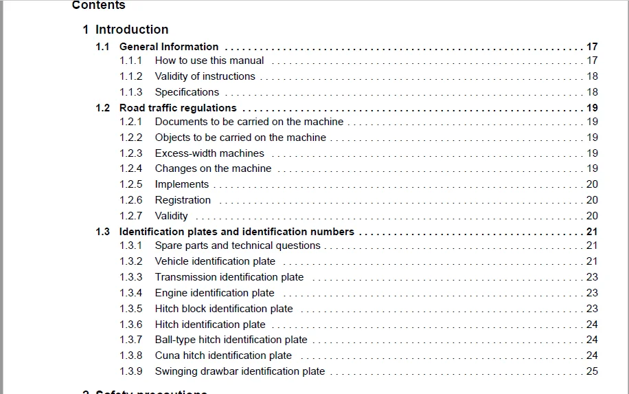
1 Introduction
1 1 General Information 17
1 1 1 How to use this manual 17
1 1 2 Validity of instructions 18
1 1 3 Specifications 18
1 2 Road traffic regulations 19
1 2 1 Documents to be carried on the machine 19
1 2 2 Objects to be carried on the machine 19
1 2 3 Excess-width machines 19
1 2 4 Changes on the machine 19
1 2 5 Implements 20
1 2 6 Registration 20
1 2 7 Validity 20
1 3 Identification plates and identification numbers 21
1 3 1 Spare parts and technical questions 21
1 3 2 Vehicle identification plate 21
1 3 3 Transmission identification plate 23
1 3 4 Engine identification plate 23
1 3 5 Hitch block identification plate 23
1 3 6 Hitch identification plate 24
1 3 7 Ball-type hitch identification plate 24
1 3 8 Cuna hitch identification plate 24
1 3 9 Swinging drawbar identification plate 25
2 Safety precautions
2 1 Safety rules 26
2 1 1 Identification of warning and danger signs 26
2 1 2 Intended use 27
2 1 3 General safety and accident prevention regulations 27
2 1 4 Transporting passengers, co-driver, operating personnel 28
2 1 5 Driving operations 28
2 1 6 Leaving the vehicle 29
2 1 7 Vehicle-mounted implements 29
2 1 8 P t o shaft operation 30
2 1 9 Air conditioner 30
2 1 10 Adjustment and maintenance work 31
2 1 11 First aid measures 31
2 2 Safety features on the vehicle 33
2 2 1 Grab handles 33
2 2 2 Wheel chocks 33
Positioning the wheel chocks 33
2 2 3 Battery isolating switch 33
2 2 4 Fire extinguisher 34
2 3 Safety decals 35
2 3 1 Layout and purpose 35
2 3 2 Positioning on the vehicle 36
4 000 293 953 0 – BA XERION – 02/06
3842
000 515 130 0 (2) 36
000 516 060 0 (8) 37
000 515 133 0 (17) 38
000 515 134 0 (33) 38
000 515 137 1 (36) 39
000 515 138 0 (39) 39
000 515 141 0 (40) 40
000 515 131 0 (46) 40
000 515 132 0 (47) 41
000 515 135 0 (48) 41
000 515 136 0 (49) 42
000 515 139 1 (50) 42
000 515 140 1 (51) 43
000 515 143 1 (52) 43
3 Specifications
3 1 Country-specific specifications 44
3 2 Engine 44
3 2 1 Engine specifications 44
3 2 2 Cooling system 44
3 2 3 Electric system 44
3 2 4 Fuel tank 44
3 3 Angle of inclination 44
3 3 1 Angle of vehicle inclination 44
3 4 Drive 45
3 4 1 Drive 45
3 4 2 Transmission 45
3 4 3 Axles 45
3 5 P t o shafts 45
3 5 1 Tail p t o shaft 45
3 6 Power lifts 46
3 6 1 Front power lift 46
3 6 2 Tail power lift 46
3 7 HITCHES 46
3 7 1 Allowed load 46
3 8 Steering 47
3 8 1 Design 47
3 9 Brakes 47
3 9 1 Service brake 47
3 9 2 Parking brake 47
3 9 3 Trailer brake 47
3 10 Hydraulic system 48
3 10 1 Main circuit (power lift, additional control units) 48
3 10 2 Steering circuit (Oil cooling, steering, brake) 48
3 10 3 Emergency circuit (emergency steering) 48
3 10 4 Power hydraulics 48
3 11 Additional control units 48
3 11 1 Additional control units 48
3 11 2 Power-beyond ports 49
000 293 953 0 – BA XERION – 02/06 5
3842
3 12 Socket outlets 49
3 12 1 Socket, 56-pin 49
3 12 2 Signal socket, 7-pin 50
3 12 3 Signal socket (ISO), 9-pin 50
3 12 4 Unit socket (ISO), 9-pin 50
3 12 5 Socket(s), 3-pin 50
3 12 6 Sockets, 7-pin 50
3 12 7 Diagnosis socket 50
3 13 Tightening torques 50
3 13 1 Driven steering axles 50
4 Before initial operation
4 1 Check list for initial operation 51
4 1 1 Use and responsibilities 51
4 1 2 Set-up work upon delivery 51
4 1 3 Set-up work prior to handing-over 51
4 1 4 Engine 51
4 1 5 Chassis / wheels 52
4 1 6 Transmission / Brakes 52
4 1 7 Power lift / hitches 52
4 1 8 Cab / hydraulic system / electric system 52
4 1 9 Coverings / protective guards 53
4 1 10 Decals 53
4 1 11 Functional check 53
5 Prior to any commissioning
5 1 Mirrors 54
5 1 1 Adjusting the external mirrors 54
Rough adjustment of external mirror 54
Fine adjustment of external mirror 54
5 1 2 Adjusting the side view mirror 55
5 2 Steering stops 56
5 2 1 Use 56
5 2 2 Fitting the steering stops 57
5 3 Mud guard on floating axle 58
5 3 1 Adapting the mud guard: 58
5 3 2 Mud guard positions 59
5 4 SELECTING IMPLEMENT COMBINATIONS 60
5 4 1 Allowed axle loads 60
5 4 2 Necessary data 61
5 4 3 Calculating the permissible axle loads 62
Actual total weight 62
Minimum front axle load 62
Minimum rear axle load 62
Actual front axle load 62
Actual front axle load 62
5 4 4 Calculating the ballast 63
Minimum front ballast 63
Minimum tail ballast 63
6 000 293 953 0 – BA XERION – 02/06
3842
Additional front ballast 63
Additional rear ballast 63
5 4 5 Example of an application: Ordered combination on the tail three-point hitch 64
Necessary data 64
Actual total weight 64
Minimum front axle load 64
Minimum rear axle load 64
Actual front axle load 65
Actual front axle load 65
Minimum front ballast 65
Additional front ballast 66
Actual total weight 66
Minimum front axle load 66
Minimum rear axle load 66
Actual front axle load 66
Actual front axle load 66
5 5 Weights 68
5 5 1 Tail weights 69
5 5 2 Centre weights 70
6 Overview of controls
6 1 Cab 71
6 1 1 Cab roof 71
6 1 2 Roll-up sun screens 73
6 1 3 Switch console 74
6 1 4 Multi-function handle 76
6 1 5 B-column switch console 77
6 2 Automatic air conditioner 79
6 2 1 Use 79
6 2 2 Switching on the automatic air conditioner 79
6 2 3 Automatic cab temperature adjustment 79
6 2 4 Manual cab temperature adjustment 80
6 2 5 Adjusting the air conditioner air flow 81
Heating the leg area 82
6 2 6 Dehumidifying the cab windowpane 82
6 2 7 Displaying the outside temperature 83
6 2 8 Converting the temperature display to °Fahrenheit 83
6 3 Steering column 84
6 3 1 Vehicle information unit 84
6 3 2 Multi-function switch 84
6 3 3 Adjusting the steering column 85
Adjusting the steering column 85
Tilting the steering column 85
Adjusting the steering wheel height 85
6 4 Adjusting the operator’s seat 86
6 4 1 Adjusting the armrests 86
Sliding the right arm rest forward / backward 86
Adjusting the angle of the right armrest 86
Adjusting the angle of the left arm rest 86
000 293 953 0 – BA XERION – 02/06 7
3842
Adjusting the height of the left armrest 87
6 4 2 Adjusting the seat 87
Adjusting the seat depth 87
Adjusting the seat inclination 87
Sliding the seat forward / backward 87
Rotating the seat 88
6 4 3 Adjusting the back rest 88
Extending the back rest 88
Adjusting the back rest inclination 89
6 4 4 Adjusting the seat comfort 89
Activating / deactivating the horizontal suspension 89
Adjusting the seat height / operator’s weight 89
Adjusting the shock absorption 90
Switching on the seat heater 90
Adjusting the lumbar support 90
6 5 Power lifts 91
6 5 1 Front external operation 91
6 5 2 Tail external operation 91
6 6 Socket outlets 92
6 6 1 Vehicle front 92
6 6 2 Vehicle tail 92
6 6 3 Cab 93
6 7 Central terminal compartment 94
6 7 1 Opening the central terminal compartment 94
6 7 2 Fuses 94
6 7 3 Relays 97
7 Driving and Transport
7 1 Starting the engine 100
7 2 Lighting and warning signs 102
7 2 1 Adjusting the drive lights 102
7 2 2 Warning plates 102
7 3 Selecting the transmission mode 103
7 3 1 Automotive mode 103
7 3 2 Manual mode 103
7 4 Driving off 104
7 4 1 Before driving off 104
7 4 2 Driving in automotive mode 104
7 4 3 Driving with the parking brake on 105
7 4 4 Driving off in manual mode 105
7 5 Driving 108
7 5 1 During travel 108
7 5 2 Road travel 109
7 5 3 Pushing operation 109
7 5 4 Operating ranges 110
Change drive range 110
7 5 5 Changing the direction of travel 111
Selecting the direction of travel at vehicle standstill 111
Changing the direction of travel while driving 112
8 000 293 953 0 – BA XERION – 02/06
3842
7 5 6 Activating the vibration dampening 113
7 6 Cruise control 114
7 6 1 Purpose 114
7 6 2 Storing cruise control values 114
7 6 3 Activating cruise control values 115
7 6 4 Changing cruise control values 116
7 6 5 Deactivating the cruise control 116
7 7 Sets the engine speed 118
7 7 1 Adjusting the minimum engine speed 118
7 7 2 Storing the fixed engine speed 119
7 7 3 Activating/changing the fixed engine speed 120
7 8 Differential locks 121
7 8 1 Engaging the centre differential lock 121
7 8 2 Engaging the axle locks 122
7 8 3 Releasing the differential locks manually 123
7 8 4 Automatic differential lock monitoring device 123
7 9 Brakes 124
7 9 1 Shifting the transmission to neutral 124
7 9 2 Foot brake 124
Manual mode 125
7 9 3 Parking brake 125
7 9 4 inching pedal 126
7 10 Parking the vehicle 127
7 10 1 Limp Home 127
7 10 2 Towing the XERION 129
Towing with the engine running 129
Towing with the engine standing still 129
8 Fieldwork settings
8 1 CAB POSITIONS 130
8 1 1 Engine position 130
SADDLE TRAC 130
8 1 2 Centre position 130
TRAC / TRAC VC 130
8 1 3 Tail position 130
TRAC VC 130
8 1 4 Rotating the cab 131
8 1 5 Steering with cab in tail position 132
8 1 6 Lighting with the cab in tail position 132
8 2 Front power lift 133
8 2 1 Front power lift – overview 133
8 2 2 Connecting the implements in a height-variable / rigid manner 134
Connecting the implements in a height-variable manner 134
Connecting the implements in a rigid manner: 134
8 2 3 Adjusting the lifting power and the lifting path 135
Longer lifting path / smaller lifting power 135
Shorter lifting path / larger lifting power 135
8 2 4 External operation 135
8 2 5 Hitching an implement 136
000 293 953 0 – BA XERION – 02/06 9
3842
Hitching up using the external pushbuttons 136
8 2 6 Adjusting and connecting the upper link 137
8 2 7 Unhitching an implement 137
8 2 8 Parking position 137
8 3 Tail power lift 138
8 3 1 Tail power lift – overview 138
8 3 2 External operation 138
8 3 3 Hitching an implement 138
Hitching up using the external pushbuttons 139
8 3 4 Adjusting and connecting the upper link 140
8 3 5 Adjusting and connecting the hydraulic upper link 140
8 3 6 Unhitching an implement 141
8 3 7 Adjusting the lower link clearance 142
8 3 8 Changing the implement lift angle 142
8 3 9 Adjusting the lift brace length 143
8 3 10 Adjusting the lower links to variable height 143
8 3 11 Adjusting the lower link to a rigid position 143
8 3 12 Adjusting the lower link to a floating / rigid position 144
Adjusting the lower link to be laterally rigid 144
Adjusting the automatic / floating position 144
8 4 Slewing power lift 145
8 4 1 Adapting the category 145
8 4 2 Adjusting the height flexibility 145
8 5 HITCHES 146
8 5 1 Trailer hitch 146
Adjusting the trailer hitch position 146
Removing the trailer hitch 147
Hitching an implement 147
Unhitching an implement 148
8 5 2 Ball-type hitch 148
Installing the ball-type hitch 148
Connecting an implement to the ball-type hitch 149
Disconnecting an implement from the ball-type hitch 149
8 5 3 Cuna hitch 150
Relocating the Cuna hitch 150
Removing the Cuna hitch 150
Hitching/unhitching implements 150
8 5 4 Swinging drawbar 151
Short / long swinging drawbar 151
Swinging drawbar with trailer hitch ball 152
8 5 5 Hitch block with Piton Fix 152
8 5 6 Hitch block with ball 153
8 5 7 Forced steering device 154
Fitting variants 154
Fitting the forced steering device 155
Hitching an implement 156
8 5 8 Special hitch with ball 156
Hitching a semitrailer / an implement 157
10 000 293 953 0 – BA XERION – 02/06
3842
8 6 VEHICLE-MOUNTED IMPLEMENTS 158
8 6 1 Adjusting the floating axle lock 158
8 7 P t o shafts and universal drive shaft 159
8 7 1 Replacing the stub of p t o shaft 160
8 7 2 Installing the universal drive shaft 160
8 8 Hydraulic connections 162
8 8 1 Front hydraulic ports 163
8 8 2 Tail hydraulic ports 163
8 8 3 Load Sensing 164
8 8 4 White hydraulic ports 164
Connecting the external consumer 164
8 8 5 Power hydraulics 165
8 8 6 Disconnecting the hydraulic hoses 165
8 9 TRAILER BRAKE CONNECTIONS 167
8 9 1 Before connecting the trailer brake system 167
8 9 2 Connecting the trailer to the compressed-air brake system 167
8 9 3 Connecting the trailer to the hydraulic brake system 168
8 10 INSTALLATION OF ELECTRIC AND ELECTRONIC DEVICES 169
8 10 1 Installation of mobile communication systems 169
8 10 2 Installing additional controls/displays 170
9 Operation CEBIS
9 1 CLAAS CEBIS on-board information system 171
9 2 Controls and displays 172
9 2 1 C keys 172
9 2 2 Rotary switch D 172
9 2 3 Multi-function handle 173
Tail power lift 173
9 2 4 Road travel display 174
9 2 5 Working display 176
9 2 6 Windows 178
9 3 Hydraulic system configuration 180
9 3 1 Calling up the Hydraulic system configuration menu 180
9 3 2 Configuring the power lift 180
Opening the rear lifting equipment menu 180
Setting the tractive force / position control 181
Setting the lift limit 181
Setting the lifting equipment drop rate 182
9 3 3 Configuring the hydraulic ports 183
Setting the oil flow rate 183
Setting the reaction time 184
Setting the actuated time 186
Activating/deactivating the external control 187
Activating/deactivating the priority 187
9 4 Vehicle configuration 189
9 4 1 Calling up the Vehicle configuration menu 189
9 4 2 Ground speed setting 189
Calling up the Ground speed configuration menu 190
Setting cruise control values 190
000 293 953 0 – BA XERION – 02/06 11
3842
Setting the creeping speed 191
9 4 3 Engine settings 192
Calling up the Engine settings menu 192
Setting the load-based engine droop 192
Storing fixed engine speeds 194
9 4 4 Transmission 195
Calling up the Transmission menu 196
Setting the aggressiveness 196
Activating / deactivating the manual mode 197
9 4 5 Calibration 198
Calling up the calibration menu 198
Learning the pulses per 100m 199
Learning the front power lift 199
Learning the tail power lift 200
9 5 Steering settings 201
9 5 1 Special steerings 202
Standard steering 202
4-wheel steering 203
Rear axle offset steering 204
Diagonal crab steering 204
Crab steering 205
Ground speed control lever 205
Synchronous steering 206
9 5 2 Calling up the Steering menu 206
9 5 3 Activating a special steering 206
9 5 4 Selecting a special steering 208
9 5 5 Configuring the special steering 209
Maximum rear axle steering angle 210
Steering to the max rear axle steering angle 210
Maximum diagonal crab steering steering angle 211
Steering to the max diagonal crab steering steering angle 211
Centering aid On/Off 212
Position of steering pole axis 213
Examples of applications: 213
9 6 CEBIS 214
9 6 1 Calling up the CEBIS menu 214
9 6 2 Configuring the rotary switch 214
Changing the rotary switch levels 214
Priority of rotary switch levels 215
9 6 3 Configuring the function keys F1 to F4 216
9 6 4 Configuring the rocker switch on the ground speed control lever 217
9 6 5 CEBIS – Settings 217
Monitor brightness 218
Language, Distance unit 218
Date / Time 219
9 6 6 Reset 219
Resetting the trip milage counter 219
Resetting the 500 h and 1500 h maintenance counter 220
Resetting the machine to the factory settings 220
12 000 293 953 0 – BA XERION – 02/06
3842
9 7 Supplementary driving information 221
9 7 1 Calling up supplementary driving information 221
Vehicle 221
Engine 222
Transmission 222
Hydraulic system 223
Alarms 223
Maintenance 223
CEBIS 224
9 8 Implement 225
9 8 1 Calling up the Implement menu 225
9 8 2 Setting the working width 225
9 8 3 Defining the working position 226
9 8 4 Configuring the distance calculation 227
9 9 Area counter 228
9 9 1 Calling up the area counter menu 228
9 9 2 Calling up the daily counter 228
9 9 3 Calling up the total counter 229
9 9 4 Resetting the daily counter 230
10 Operation of CLAAS COMMUNICATOR
10 1 Power hydraulics 231
10 1 1 Controls 231
10 1 2 Scope of functions 232
10 1 3 Switching the control mode on / off 232
Control mode ON 232
Control mode OFF 232
10 1 4 Setting the output flow 233
10 1 5 Setting the swivel angle 234
10 1 6 Setting the operating mode 234
10 1 7 Activating the power hydraulics 235
Changing the flow rate 236
10 1 8 Changing the direction of flow 237
10 1 9 Switching the power hydraulics off 238
10 1 10Displaying diagnosis data 238
10 2 Service menu 239
10 2 1 Scope of functions 239
10 2 2 Calling up the service menu 239
10 2 3 Service menu – Overview 240
10 2 4 Selecting a menu 241
10 2 5 Information menu 241
10 2 6 Image settings menu 241
Setting the monitor contrast 242
Setting the monitor brightness 242
10 2 7 Time and date menu 242
Setting the time 242
10 2 8 Memory administration menu 243
Displaying the memory capacity 243
Deleting a memory location 244
000 293 953 0 – BA XERION – 02/06 13
3842
10 2 9 Country-specific settings menu 244
Setting the language 245
Setting the format 245
Setting the unit 246
10 2 10Additional function menu 247
11 Fieldwork
11 1 Headlights 248
11 1 1 Switching on the worklights 248
11 2 Trailer brake 250
11 2 1 Compressed-air brake 250
11 2 2 Hydraulic trailer brake 250
11 2 3 Hydraulic trailer brake, “Italian” type 251
11 3 P t o shaft / auxiliary power take-off 252
11 3 1 To be observed before putting into operation 252
11 3 2 Engaging the tail p t o shaft 253
11 3 3 External operation of tail p t o shaft 254
11 3 4 Engaging the auxiliary power take-off 255
11 4 Power lifts 256
11 4 1 Operating the front power lift 256
11 4 2 Adjusting the tail power lift working position 257
11 4 3 Operating the electronic lift control 257
11 5 Hydraulic vehicle-mounted implements 259
11 5 1 Scope of functions 259
11 5 2 White hydraulic port 259
11 5 3 Red / yellow / green / blue hydraulic port 260
Raising an implement 260
Lowering an implement 261
11 5 4 Configuring the hydraulic ports 261
11 6 Central lubrication system 263
11 6 1 Purpose 263
11 6 2 Switching on the central lubrication system 263
12 Faults and remedies
12 1 Air conditioner 264
12 1 1 Fault code table 264
12 1 2 Faults and remedies 264
12 2 Central lubrication system 267
12 2 1 Faults and remedies 267
13 Maintenance
13 1 Important maintenance instructions 268
13 1 1 Important maintenance instructions and safety rules 268
13 1 2 Lubrication 268
13 1 3 Brakes 269
13 1 4 Wheels / tyres 269
13 1 5 Hydraulic system 271
13 1 6 Electrical system 271
13 1 7 Air conditioner 272
13 1 8 Protective guards 273
14 000 293 953 0 – BA XERION – 02/06
3842
13 1 9 Spare parts 273
13 1 10P t o shaft-driven implements 273
13 1 11Welding 274
13 2 Maintenance schedules 276
13 2 1 Hydraulic system / Steering 276
13 2 2 Transmission 276
13 2 3 Compressed-air system / Brakes 277
13 2 4 Axles 278
13 2 5 Cab / air conditioner 278
13 2 6 Hitches / bolts 279
13 2 7 Central lubrication system 280
13 3 Lubricants charts 281
13 3 1 Hydraulic system 281
13 3 2 Transmission 281
13 3 3 Brakes 281
13 3 4 Axles 282
13 3 5 Cab / air conditioner 282
13 4 Hydraulic system 283
13 4 1 Checking the hydraulic oil level 283
13 4 2 Changing the hydraulic oil 283
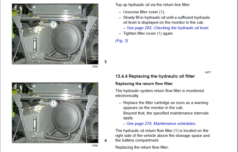
13 4 3 Topping up hydraulic oil 284
13 4 4 Replacing the hydraulic oil filter 284
Replacing the return flow filter 284
Replace pressure filter 285
Replacing the suction filter 286
Replacing the fresh air filter element 286
13 4 5 Draining the leakage oil collecting container 287
Tail leakage oil collecting container 287
Front leakage oil collecting container 287
13 5 Transmission 288
13 5 1 Checking the ground drive transmission oil level 288
13 5 2 Changing the ground drive transmission oil 288
13 5 3 Topping up ground drive transmission oil 289
13 5 4 Replacing the ground drive transmission fine filter 289
13 5 5 Checking the p t o transmission oil level 290
13 5 6 Changing the p t o transmission oil 290
13 5 7 Topping up p t o transmission oil 291
13 6 Compressed-air system / Brakes 292
13 6 1 Compressed-air connection 292
13 6 2 Checking / cleaning the drain valve 293
13 6 3 Checking / retightening the straps 293
13 6 4 Have compressed-air accumulator checked 293
13 6 5 Checking the pressure controller 294
13 6 6 Checking the antifreeze agent level 294
Switching off the antifreeze pump 294
13 6 7 Checking the parking brake air gap 295
13 6 8 Releasing the parking brake 295
000 293 953 0 – BA XERION – 02/06 15
3842
13 7 Axles 296
13 7 1 Checking the planetary gear oil level 296
13 7 2 Changing the planetary gear oil 297
13 7 3 Checking the differential oil level 297
13 7 4 Changing the differential oil 298
13 7 5 Cleaning the venting valves 298
13 7 6 Checking the track adjustment 299
13 7 7 Checking the kingpin bearings for absence of play 299
13 8 Air conditioner 300
13 8 1 Cleaning the condenser 300
13 8 2 Checking the refrigerant level 301
13 8 3 Checking the filter receiver drier 301
13 9 Cab 302
13 9 1 Cleaning / replacing the cab filters 302
13 9 2 Cleaning the units located in the cab roof 302
13 9 3 Checking the windscreen washer 303
13 9 4 Have fire extinguisher checked 303
13 10HITCHES 304
13 10 1Ball-type hitches 304
Checking the ball-type hitch for wear 304
Checking the special hitch with ball for wear 304
Adjusting the height play of the ball-type hitch 305
13 11Central lubrication system 306
13 11 1Checking the level 306
13 11 2Filling the grease container 306
13 11 3Function testing 307
14 Engine maintenance
14 1 Important maintenance instructions 308
14 1 1 Important maintenance instructions and safety rules 308
14 1 2 Cooling water and air intake hoses 308
14 1 3 Coolant 308
14 1 4 Belts 308
14 1 5 Cleaning the engine compartment and hazard areas 309
14 1 6 Warranty on non genuine CATERPILLAR products 309
14 1 7 Engine oil 309
14 2 Maintenance schedule 310
14 2 1 CATERPILLAR C9 engine 310
14 3 Lubricants chart 312
14 3 1 CATERPILLAR C9 engine 312
Coolant 312
14 4 Opening the engine facings 313
14 4 1 Folding up the front radiator grille 313
14 4 2 Opening the engine bonnet 313
14 4 3 Opening the side engine panels 314
14 5 ENGINE OVERVIEW 315
14 5 1 CATERPILLAR C9 315
16 000 293 953 0 – BA XERION – 02/06
3842
14 6 Fuel system 316
14 6 1 Filling the fuel tank 316
14 6 2 Checking the water separator / draining water 317
14 6 3 Replacing the fuel pre-filter cartridge 317
14 6 4 Fuel filter 319
14 6 5 Replacing the fuel filter cartridge 319
14 6 6 Bleed fuel system 320
14 7 ENGINE OIL 321
14 7 1 Checking the engine oil level 321
14 7 2 Draining the engine oil 322
14 7 3 Changing the engine oil filter 322
14 7 4 Topping up engine oil 323
14 8 Cooling system 324
14 8 1 Checking the frost resistance 324
14 8 2 Checking the coolant level 325
14 8 3 Changing the coolant 326
14 8 4 Topping up coolant 327
14 8 5 Cleaning the radiator unit 328
14 8 6 Cleaning the cooling air intake screen 328
14 9 AIR-INTAKE SYSTEM 330
14 9 1 Checking air-intake screen for dirt 330
14 9 2 Check air intake hose for damage 330
14 9 3 Checking the mounting clamps of the charge-air pipes 331
14 9 4 Dry-type air filter 332
14 9 5 Cleaning the air filter 332
Cleaning the main cartridge 333
Installing the main cartridge 334
14 9 6 Replacing the air filter safety cartridge 335
Removing and installing the safety cartridge 336
14 10V-BELTS / VALVES 337
14 10 1Fan / alternator drive belt 337
14 10 2Checking the drive belt condition 337
14 11Electric system 338
14 11 1Batteries 338
14 11 2Battery isolating switch 338
14 11 3Alternator 339
15 Lubrication chart
15 1 Lubricants and lubrication instructions 340
15 1 1 Grease 340
15 1 2 Symbols and abbreviations used 340
15 2 Greasing cycles 341
15 3 Lubrication points 343
15 3 1 50 / 500 working hours 343
CLAAS XERION 3300 OPERATOR’S MANUAL – PDF DOWNLOAD:
IMAGES PREVIEW OF THE MANUAL:
PLEASE NOTE:
- This is the same manual used by the DEALERSHIPS to SERVICE your vehicle.
- The manual can be all yours – Once payment is complete, you will be taken to the download page from where you can download the manual. All in 2-5 minutes time!!
- Need any other service / repair / parts manual, please feel free to contact us at heydownloadss @gmail.com . We may surprise you with a nice offer
S.V