CLAAS XERION 3300 Technical & Electric System Service Manual – PDF DOWNLOAD
Original price was: $78.00.$29.95Current price is: $29.95.
CLAAS XERION 3300 Technical & Electric System Service Manual – PDF DOWNLOAD
Description
CLAAS XERION 3300 Technical & Electric System Service Manual – PDF DOWNLOAD
DESCRIPTION:
CLAAS XERION 3300 Technical & Electric System Service Manual – PDF DOWNLOAD
1 Introduction
Structure of electrical documentation
Circuit diagram
General:
Following the representation of schematic diagrams, all electric circuits are represented in individual circuit diagrams. Some explanations are given below in order to make understanding easier.
xer-e-01a The numbering can be found on the respective cover sheet and on the circuit diagram. Depending on the machine serial no., the equipment fitted and the country specification, there may be several individual circuit diagrams for one single function (01a, 01b, 01c, …).
TABLE OF CONTENTS:
CLAAS XERION 3300 Technical & Electric System Service Manual – PDF DOWNLOAD
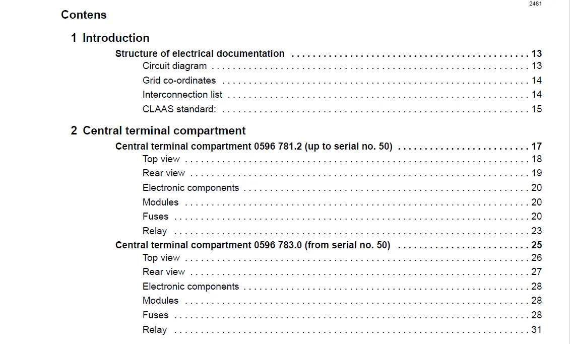
Contens 3
1 Introduction 13
Structure of electrical documentation 13
Circuit diagram 13
Grid co-ordinates 14
Interconnection list 14
CLAAS standard: 15
2 Central terminal compartment 17
Central terminal compartment 0596 7812 (up to serial no 50) 17
Top view 18
Rear view 19
Electronic components 20
Modules 20
Fuses 20
Relay 23
Central terminal compartment 0596 7830 (from serial no 50) 25
Top view 26
Rear view 27
Electronic components 28
Modules 28
Fuses 28
Relay 31
3 Modules 33
Module representation 33
Overview 1 34
Overview 2 35
Overview 3 36
Module assignment 37
Module A6 – Automatic air conditioner 37
Cab fan speed controller module A7 39
Module A15 – Electronic engine control CAT 40
Module A30 – CEBIS terminal XT 42
Module A55 electrohydraulic steering (EHL) connector X1, up to serial no 50 43
Module A55 electrohydraulic steering (EHL) connector X2, up to serial no 50 46
Module A55 electrohydraulic steering (EHL) connector X1, from serial no 51 51
Module A55 electrohydraulic steering (EHL) connector X2, from serial no 51 54
Module A56 – VDC (Vehicle drive control) 58
Module A57 – Gearshift control (TCU) 64
Module A58 – Lift control (EHR) 69
Module A59-1 Valve control (VCU) 71
Module A59-2 – Valve control (VCU) 73
Module A60 – Hydraulic control unit (HYD) 74
Module A61 – Fieldwork computer XERION (XIF) 79
Module A62 – External control (EXT) 84
Module A70 – Power Hydraulics (PHM) 87
4 Circuit diagrams 89
01a Main power supply, diesel engine electric starting motor 89
Circuit diagram up to serial no 50 (DIN A 3) 90
Key to diagram 91
Description of function 91
Diagnosis table 1 91
Connector pin assignment 92
Interconnection list 92
01b Main power supply, diesel engine electric starting motor 93
Circuit diagram from serial no 51 (DIN A 3) 94
Key to diagram 95
Description of function 95
Diagnosis table 1 95
Connector pin assignment 96
Interconnection list 96
02a Starting the diesel engine, diesel engine speed adjustment 97
Circuit diagram up to serial no 50 (DIN A 3) 98
Key to diagram 99
Description of function 99
Electronic throttle switching logics101
Diagnosis table 2101
Connector pin assignment102
Interconnection list102
02b Starting the diesel engine, diesel engine speed adjustment105
Circuit diagram from serial no 51 (DIN A 3)106
Key to diagram107
Description of function107
Electronic throttle switching logics109
Diagnosis table 2109
Connector pin assignment111
Interconnection list111
03a Diesel engine cut-off system113
Circuit diagram (DIN A3)114
Key to diagram115
Measuring value table115
Description of function115
Diagnosis table 3116
Connector pin assignment116
Interconnection list116
04a Road travel circuit, constant pressure circuit117
Circuit diagram (DIN A3)118
Key to diagram119
Measuring value table119
Description of function120
Diagnosis table 4121
Connector pin assignment122
Interconnection list122
05a Terminal123
Circuit diagram (DIN A3)124
Key to diagram125
Description of function125
Connector pin assignment126
Interconnection list126
06a CAN bus127
Circuit diagram up to serial no 50 (DIN A 3)128
Key to diagram129
Description of function130
CAN bus network130
Measured value table 250 kB vehicle CAN bus (Vehicle CAN bus)131
Measured value table 250 kB CAN bus hydraulic system131
Measured value table J1939 CAN bus131
Measured value table ISO 11783 CAN bus131
Connector pin assignment132
Interconnection list132
06b CAN bus137
Circuit diagram from serial no 51 (DIN A 3)138
Key to diagram139
Description of function140
CAN bus network141
Measured value table 250 kB vehicle CAN bus (Vehicle CAN bus)141
Measured value table 250 kB CAN bus hydraulic system141
Measured value table J1939 CAN bus142
Measured value table ISO 11783 CAN bus142
Connector pin assignment143
Interconnection list143
07a Rear PTO shaft circuit147
Circuit diagram up to serial no 50 (DIN A 3)148
Key to diagram149
Measuring value table149
Description of function150
Logics table: Rear PTO switch S114 (internal, in cab)151
Logics table: Rear PTO switch U30 (external, on mud guard)151
Diagnosis table 7151
Connector pin assignment153
Interconnection list153
07b Tail PTO shaft circuit155
Circuit diagram from serial no 51 (DIN A 3)156
Key to diagram157
Measuring value table157
Description of function158
Logics table: Rear PTO switch S114 (internal, in cab)159
Logics table: Rear PTO switch U30 (external, on mud guard)159
Diagnosis table 7159
Connector pin assignment161
Interconnection list161
08a PTO shaft circuit II Auxiliary power take-off163
Circuit diagram up to serial no 50 (DIN A 3)164
Key to diagram165
Measuring value table165
Description of function165
Logic table: PTO 2 auxiliary power take-off switch S113167
Diagnosis table 8167
Connector pin assignment169
Interconnection list169
08b PTO shaft circuit II Auxiliary power take-off / Power hydraulics171
Circuit diagram from serial no 51 (DIN A 3)172
Key to diagram173
Measuring value table173
Description of function173
Logic table: PTO 2 auxiliary power take-off switch S113175
Diagnosis table 8175
Connector pin assignment177
Interconnection list177
09a External operation (EXT module)179
Circuit diagram (DIN A3)180
Key to diagram181
Description of function181
Diagnosis table 9181
Connector pin assignment183
Interconnection list183
10a ISO terminal, ISO operation185
Circuit diagram (DIN A3)186
Key to diagram187
Description of function187
Diagnosis table 10188
Interconnection list188
11a ISO signal socket191
Circuit diagram (DIN A3)192
Key to diagram193
Description of function193
Diagnosis table 11193
Connector pin assignment194
Interconnection list194
12a Programmable functions (F keys)197
Circuit diagram up to serial no 50 (DIN A 3)198
Key to diagram199
A52 Multifunction handle module200
Description of function200
Diagnosis table 12200
Connector pin assignment202
Interconnection list202
12b Programmable functions (F keys)203
Circuit diagram from serial no 51 (DIN A 3)204
Key to diagram205
A52 Multifunction handle module205
Description of function206
Diagnosis table 12206
Connector pin assignment207
Interconnection list207
13a Connection of semi-mounted implements209
Circuit diagram (DIN A3)210
Key to diagram211
Description of function211
Connector pin assignment212
Interconnection list212
20a Front hydraulics215
Circuit diagram (DIN A3)216
Key to diagram217
A52 Multifunction handle module218
Measuring value table218
Description of function219
Diagnosis table 20220
Connector pin assignment222
Interconnection list222
21a Tail hydraulics EHR223
Circuit diagram (DIN A3)224
Key to diagram225
A52 Multifunction handle module226
Measuring value table226
Description of function226
Diagnosis table 21230
Connector pin assignment231
Interconnection list232
22a Service valves, additional control units233
Circuit diagram (DIN A3)234
Key to diagram235
Measuring value table235
Description of function236
Diagnosis table 22237
Connector pin assignment239
Interconnection list239
23a Blue service valve241
Circuit diagram (DIN A3)242
Key to diagram243
Measuring value table243
Description of function244
Diagnosis table 23244
Connector pin assignment245
Interconnection list245
26a Machine monitoring (hydraulics)247
Circuit diagram (DIN A3)248
Key to diagram249
Measuring value table249
Description of function250
Diagnosis table 26251
Connector pin assignment252
Interconnection list252
27a External sensor monitoring253
Circuit diagram (DIN A3)254
Key to diagram255
Description of function255
Connector pin assignment255
Interconnection list255
28a EHL (Autopilot), Cab position identification257
Circuit diagram up to serial no 50 (DIN A 3)258
Key to diagram259
Measuring value table260
Description of function261
Logics table: Emergency steering pump monitoring264
Logics table: Cab position identification 264
Diagnosis table 28264
Connector pin assignment267
Interconnection list267
28b EHL (Autopilot), Cab position identification271
Circuit diagram from serial no 51 (DIN A 3)272
Key to diagram273
Measuring value table274
Description of function275
Logics table: Emergency steering pump monitoring278
Logics table: Cab position identification 278
Diagnosis table 28b278
Connector pin assignment281
Interconnection list281
30a Warning beacon285
Circuit diagram (DIN A3)286
Key to diagram287
Description of function287
Connector pin assignment287
Interconnection list287
31a Locking the floating axle289
Circuit diagram (DIN A3)290
Key to diagram291
Measuring value table291
Description of function291
Diagnosis table 31292
Connector pin assignment293
Interconnection list293
32a Locking the differentials295
Circuit diagram up to serial no 50 (DIN A 3)296
Key to diagram297
Measuring value table297
Description of function298
Diagnosis table 32299
Connector pin assignment300
Interconnection list300
32b Locking the differentials301
Circuit diagram from serial no 51 (DIN A 3)302
Key to diagram303
Measuring value table303
Description of function303
Diagnosis table 32305
Connector pin assignment306
Interconnection list306
33a Cab rotation307
Circuit diagram (DIN A3)308
Key to diagram309
Measuring value table309
Description of function309
Diagnosis table 33311
Connector pin assignment312
Interconnection list312
36a Turn indicator system (Europe)313
Circuit diagram (DIN A3)314
Key to diagram315
Description of function316
Diagnosis table 36316
Connector pin assignment317
Interconnection list317
37a Windscreen wiper, Windscreen washer319
Circuit diagram up to serial no 50 (DIN A 3)320
Key to diagram321
Description of function321
Connector pin assignment321
Interconnection list321
37b Windscreen wiper323
Circuit diagram from serial no 51 (DIN A 3)324
Key to diagram325
Description of function325
Connector pin assignment325
Interconnection list325
38a Compressor-type air conditioner327
Circuit diagram (DIN A3)328
Key to diagram329
Description of function330
Connector pin assignment331
Interconnection list331
38b Automatic air conditioner333
Circuit diagram (DIN A3)334
Key to diagram335
Measuring value table336
Discription of function337
Connector pin assignment343
Interconnection list343
39a Operator’s seat345
Circuit diagram (DIN A3)346
Key to diagram347
Description of function347
Connector pin assignment347
Interconnection list347
40a Additional sockets, fuse tester349
Circuit diagram (DIN A3)350
Key to diagram351
Description of function351
Connector pin assignment351
Interconnection list351
41a Drive management, brake, parking brake353
Circuit diagram up to serial no 50 (DIN A 3)354
Key to diagram355
Measuring value table356
Description of function357
Diagnosis table 41360
Connector pin assignment362
Interconnection list362
41b Drive management, brake, parking brake367
Circuit diagram from serial no 51 (DIN A 3)368
Key to diagram369
Measuring value table370
Description of function371
Diagnosis table 41374
Connector pin assignment376
Interconnection list376
42a Limp Home381
Circuit diagram up to serial no 50 (DIN A 3)382
Key to diagram383
Description of function383
Diagnosis table 42384
Connector pin assignment384
Interconnection list384
42b Limp Home 385
Circuit diagram from serial no 51 (DIN A 3)386
Key to diagram387
Description of function387
Diagnosis table 42388
Connector pin assignment388
Interconnection list388
43a Trailer brake389
Circuit diagram (DIN A3)390
Key to diagram391
Measuring value table392
Description of function392
Diagnosis table 43393
Connector pin assignment393
Interconnection list393
44a Transmission control395
Circuit diagram up to serial no 50 (DIN A 3)396
Key to diagram397
Measuring value table398
Description of function398
Diagnosis table 44399
Connector pin assignment401
Interconnection list401
44b Transmission control403
Circuit diagram from serial no 51 (DIN A 3)404
Key to diagram405
Measuring value table406
Description of function406
Diagnosis table 44407
Connector pin assignment409
Interconnection list409
45a Lighting main circuit, taillight, position light411
Circuit diagram (DIN A3)412
Key to diagram413
Description of function413
Connector pin assignment414
Interconnection list414
46a Low beam, high beam, low beam changeover switch415
Circuit diagram (DIN A3)416
Key to diagram417
Description of function418
Connector pin assignment418
Interconnection list418
47a Worklights I421
Circuit diagram up to serial no 50 (DIN A 3)422
Key to diagram423
Description of function424
Connector pin assignment424
Interconnection list424
47b Worklights I425
Circuit diagram from serial no 51 (DIN A 3)426
Key to diagram427
Description of function428
Connector pin assignment428
Interconnection list428
48a Worklights II 429
Circuit diagram (DIN A3)430
Key to diagram431
Description of function432
Connector pin assignment432
Interconnection list432
49a Horn, brake light, back-up light433
Circuit diagram up to serial no 50 (DIN A 3)434
Key to diagram435
Description of function436
Diagnosis table 49436
Connector pin assignment436
Interconnection list436
49b Horn, brake light, back-up light439
Circuit diagram from serial no 51 (DIN A 3)440
Key to diagram441
Description of function442
Diagnosis table 49442
Interconnection list442
50a Instrument lighting, broadcast radio, mirror adjustment443
Circuit diagram (DIN A3)444
Key to diagram445
Description of function446
Connector pin assignment446
Interconnection list446
5 Diagnosis447
Diagnosis following fault codes447
Fault code CCN (CLAAS Component Number)447
FMI fault code (fault mode indicator)455
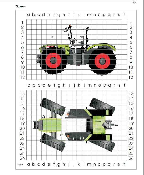
6 Location of components461
Overview (DIN A3)461
Figures461
Index463
IMAGES PREVIEW OF THE MANUAL:
Need help? Contact: [email protected]
https://vimeo.com/676550087
CLAAS XERION 3300 TECHNICAL & ELECTRIC SYSTEM SERVICE MANUAL – PDF DOWNLOAD:
PLEASE NOTE:
- This is the SAME MANUAL used by the dealerships to diagnose your vehicle
- No waiting for couriers / posts as this is a PDF manual and you can download it within 2 minutes time once you make the payment.
- Your payment is all safe and the delivery of the manual is INSTANT – You will be taken to the DOWNLOAD PAGE.
- So have no hesitations whatsoever and write to us about any queries you may have : heydownloadss @gmail.com
S.M