CLAAS XERION 3300 Technical & Hydraulic System Service Manual – PDF DOWNLOAD
Original price was: $80.00.$24.95Current price is: $24.95.
CLAAS XERION 3300 Technical & Hydraulic System Service Manual – PDF DOWNLOAD
Description
CLAAS XERION 3300 Technical & Hydraulic System Service Manual – PDF DOWNLOAD
DESCRIPTION:
CLAAS XERION 3300 Technical & Hydraulic System Service Manual – PDF DOWNLOAD
Description of
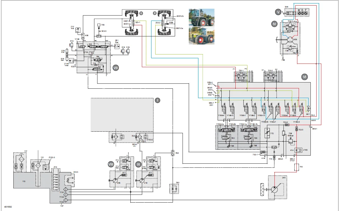
- All control units are in their neutral position. At the beginning of this example, the swash plate (17) is in its maximum end position (see also Engine OFF). When the engine is started, the pump feeds the maximum volume flow via the pump output (20) up to the spools of all control units.
- Since the spools block the flow completely, the pressure rises and is applied to the right face end of the volume flow controller (772) which is moved to the left against the compression spring (margin pressure) (21). In this process, the control edge (25) is opened so that the pressure gains access to the top side of the variable-displacement pump hydraulic cylinder (377).
- Now the swash plate (17) is moved to the “Minimum delivery” position against the control spring (15). This process takes only 10 milliseconds. In this pump position, the following happens: Volume flow is generated only to such an extent that leakage losses are compensated. The pressure required for initial actuation of a consumer is maintained. When all control units are set to their neutral positions, the load pressure input (7) is pressureless.
- To move the volume flow controller (772), the pump pressure must overcome the compression spring (margin pressure) (21) and the LS residual pressure. The pressure required for this is 20 + X bar and is referred to as “Low-pressure standby”. The “Low-pressure standby” is slightly higher than the “Margin pressure” of 20 bar. As a function of the setting of the volume flow controller (772) and of the pump leakage, “Low-pressure standby” and “Margin pressure” may be almost identical. However, the “Margin pressure” can never be higher.
- The low-pressure standby cannot be adjusted and may therefore vary from machine to machine. It changes as the leakage rate in the pump or in the system rises. The pump remains in the “Low-pressure standby” position until a control unit is actuated. In this operating position, the pump only requires little drive energy.
TABLE OF CONTENTS:
CLAAS XERION 3300 Technical & Hydraulic System Service Manual – PDF DOWNLOAD
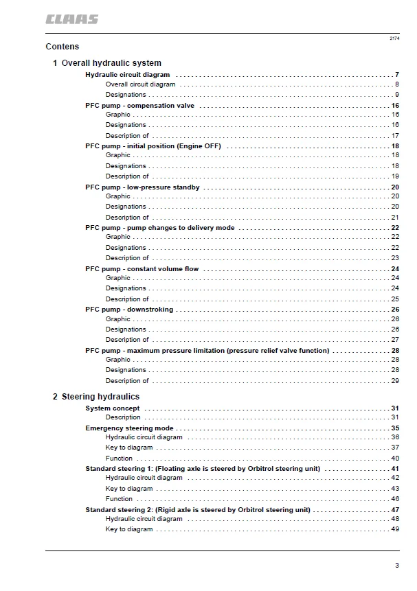
Contens 3
1 Overall hydraulic system 7
Hydraulic circuit diagram 7
Overall circuit diagram 8
Designations 9
PFC pump – compensation valve 16
Graphic 16
Designations 16
Description of 17
PFC pump – initial position (Engine OFF) 18
Graphic 18
Designations 18
Description of 19
PFC pump – low-pressure standby 20
Graphic 20
Designations 20
Description of 21
PFC pump – pump changes to delivery mode 22
Graphic 22
Designations 22
Description of 23
PFC pump – constant volume flow 24
Graphic 24
Designations 24
Description of 25
PFC pump – downstroking 26
Graphic 26
Designations 26
Description of 27
PFC pump – maximum pressure limitation (pressure relief valve function) 28
Graphic 28
Designations 28
Description of 29
2 Steering hydraulics 31
System concept 31
Description 31
Emergency steering mode 35
Hydraulic circuit diagram 36
Key to diagram 37
Function 40
Standard steering 1: (Floating axle is steered by Orbitrol steering unit) 41
Hydraulic circuit diagram 42
Key to diagram 43
Function 46
Standard steering 2: (Rigid axle is steered by Orbitrol steering unit) 47
Hydraulic circuit diagram 48
Key to diagram 49
Function 52
Fully electronic steering mode (steer-by-wire) 53
Hydraulic circuit diagram 54
Key to diagram 55
Function 58
Steering valve VI 59
Graphics 60
Key to diagram 61
3 Working hydraulics 63
Hydraulic circuit diagram 63
Working hydraulics circuit diagram 64
Key to diagram 65
Main valve block 67
Graphics 68
Key to diagram 69
EHM18 control unit 71
Graphics 72
Key to diagram 73
Neutral function 74
Float position function 75
Function: Actuation of a consumer (pressure build-up in B) 76
Cab valve block (II) 77
Graphics 78
Key to diagram 78
Description of function 79
4 Brake hydraulics 81
Hydraulic circuit diagram 81
Brake hydraulics circuit diagram 82
Key to diagram 83
Description 84
Adjusting the brake actuation following repair work 86
Main brake valve VII 88
Key to diagram 89
5 Compressed-air system 91
1- and 2-line system, 2-line system 91
Circuit diagram of 1- and 2-line system 92
Key to diagram 93
Designations of component connections 94
Circuit diagram of 2-line system 96
Key to diagram 97
Designations of component connections 98
Location of components 99
6 Auxiliary hydraulic system101
Hydraulic circuit diagram101
Auxiliary hydraulic system circuit diagram102
Key to diagram103
Components105
Description105
Multifunction valve A (7001)Multifunction valve B (7002)107
7 Testing and measuring109
Measured value tables109
Measured value table for pumps109
Working hydraulics measured value table109
Steering hydraulics measured value table110
Brake hydraulics measured value table111
Auxiliary hydraulic system measured value table111
8 Location of components113
Overview113
Main sub-assemblies (I to VIII)113
Tank115
Single components of main valve block (I)116
Single components of cab valve block (II)118
Single components of distribution block (III)119
Single components of Orbitrol steering valve (IV)120
Single components of steering sense valve (V)120
Single components of EHL (electro-hydraulic steering) valve block (VI)121
Single components of main brake valve (VII)124
Single components of working hydraulics variable-displacement pump (VIII)125
Single components of steering hydraulics variable-displacement pump (IX)125
Further single components126
Index129
A129
B129
C129
D129
E129
L129
M129
O130
P130
S130
W130
IMAGES PREVIEW OF THE MANUAL:
Contact us: [email protected]
https://vimeo.com/676556765
CLAAS XERION 3300 TECHNICAL & HYDRAULIC SYSTEM SERVICE MANUAL – PDF DOWNLOAD:
PLEASE NOTE:
- This is the SAME exact manual used by your dealers to fix your vehicle.
- The same can be yours in the next 2-3 mins as you will be directed to the download page immediately after paying for the manual.
- Any queries / doubts regarding your purchase, please feel free to contact [email protected]
S.M