Claas XERION 3300 Electric System Technical Manual PDF Download
Original price was: $86.95.$25.95Current price is: $25.95.
Claas XERION 3300 Technical Systems Electric System Manual – PDF DOWNLOAD
Description
Claas XERION 3300 Technical Systems Electric System Manual – PDF DOWNLOAD
FILE DETAILS:
Claas XERION 3300 Technical Systems Electric System Manual – PDF DOWNLOAD
Language : English
Pages : 198
Downloadable : Yes
File Type : PDF
Size: 36.4 MB
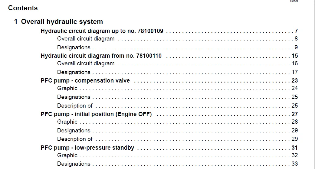
TABLE OF CONTENTS:
Claas XERION 3300 Technical Systems Electric System Manual – PDF DOWNLOAD
1 Overall hydraulic system
Hydraulic circuit diagram up to no 78100109 7
Overall circuit diagram 8
Designations 9
Hydraulic circuit diagram from no 78100110 15
Overall circuit diagram 16
Designations 17
PFC pump – compensation valve 23
Graphic 24
Designations 25
Description of 25
PFC pump – initial position (Engine OFF) 27
Graphic 28
Designations 29
Description of 29
PFC pump – low-pressure standby 31
Graphic 32
Designations 33
Description of 33
PFC pump – pump changes to delivery mode 35
Graphic 36
Designations 37
Description of 37
PFC pump – constant volume flow 39
Graphic 40
Designations 41
Description of 41
PFC pump – downstroking 43
Graphic 44
Designations 45
Description of 45
PFC pump – maximum pressure limitation (pressure relief valve function) 47
Graphic 48
Designations 49
Description of 49
2 Steering hydraulics
System concept 51
Description 51
Emergency steering mode 55
Hydraulic circuit diagram 56
Key to diagram 57
Function 60
Standard steering 1: (Floating axle is steered by Orbitrol steering unit) 61
Hydraulic circuit diagram 62
Key to diagram 63
Function 66
4
6859
Standard steering 2: (Rigid axle is steered by Orbitrol steering unit) 67
Hydraulic circuit diagram 68
Key to diagram 69
Function 72
Fully electronic steering mode (steer-by-wire) 73
Hydraulic circuit diagram 74
Key to diagram 75
Function 78
Steering valve VI 79
Graphics 80
Key to diagram 81
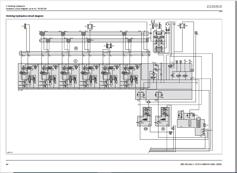
3 Working hydraulics
Hydraulic circuit diagram up to no 78100109 83
Working hydraulics circuit diagram 84
Key to diagram 85
Hydraulic circuit diagram from no 78100110 89
Working hydraulics circuit diagram 90
Key to diagram 91
Main valve block 95
Graphics 96
Key to diagram 97
EHM18 control unit 99
Graphics 100
Key to diagram 101
Neutral function 102
Float position function 103
Function: Actuation of a consumer (pressure build-up in B) 104
Three-point hitch braces 105
Graphics 106
Key to diagram 107
Swing power lift – hydraulic valve 109
Graphics 110
Key to diagram 111
Key to diagram 113
Cab valve block (II) – up to serial no 109 115
Graphics 116
Key to diagram 116
Description of function 117
Cab valve block (II) – from serial no 110 119
Graphics 120
Designations 121
Swing power lift –hydraulic cylinder 123
Graphics 124
Rotate cab, raise/lower cab – from serial no 110 125
Graphics 126
Designations 127
Front, tail quick-release couplings – up to serial no 109 129
Graphics 130
5
6859
Key to diagram 131
Front, tail quick-release couplings – from serial no 110 135
Graphics 136
Key to diagram 137
4 Brake hydraulics
Hydraulic circuit diagram 141
Brake hydraulics circuit diagram 142
Key to diagram 143
Description 144
Adjusting the brake actuation following repair work 146
Main brake valve VII 148
Key to diagram 149
Location of components – Accumulator 150
5 Compressed-air system
1- and 2-line system, 2-line system 151
Circuit diagram of 1- and 2-line system 152
Key to diagram 153
Designations of component connections 154
Circuit diagram of 2-line system 156
Key to diagram 157
Designations of component connections 158
Location of components 159
6 Auxiliary hydraulic system
Hydraulic circuit diagram 161
Auxiliary hydraulic system circuit diagram 162
Key to diagram 163
Components 165
Description 165
Multifunction valve A (7001)Multifunction valve B (7002) 167
7 Testing and measuring
Measured value tables 169
Measured value table for pumps 169
Working hydraulics measured value table 169
Steering hydraulics measured value table 170
Brake hydraulics measured value table 171
Auxiliary hydraulic system measured value table 171
8 Location of components
Overview 173
Main sub-assemblies (I to XI) 173
Tank 176
Single components of main valve block (I) 177
Single components of cab valve block (II) up to serial no 78100109 179
Single components of cab valve block (II) from serial no 78100110 180
Single components of distribution block (III) 181
Single components of Orbitrol steering valve (IV) 182
6
6859
Single components of steering sense valve (V) 182
Single components of EHL (electro-hydraulic steering) valve block (VI) 183
Single components of main brake valve (VII) 186
Single components of working hydraulics variable-displacement pump (VIII) 187
Single components of steering hydraulics variable-displacement pump (IX) 187
Single components of three-point hitch braces (X) 188
Single components of power lift swing (XI) 188
Further single components 189
IMAGES PREVIEW OF THE MANUAL:
CLAAS XERION 3300 TECHNICAL SYSTEMS ELECTRIC SYSTEM MANUAL – PDF DOWNLOAD:
PLEASE NOTE:
- This is the SAME exact manual used by your dealers to fix your vehicle.
- The same can be yours in the next 2-3 mins as you will be directed to the download page immediately after paying for the manual.
- Any queries / doubts regarding your purchase, please feel free to contact [email protected]
S.V