Claas XERION 3300 XERION 3800 Technical Systems Electric System Manual – PDF DOWNLOAD
Original price was: $86.95.$28.95Current price is: $28.95.
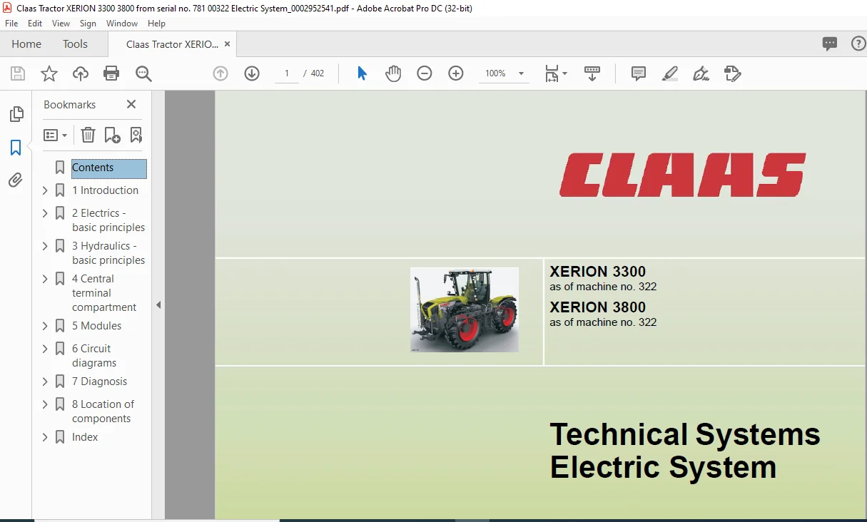
Claas XERION 3300 XERION 3800 Technical Systems Electric System Manual – PDF DOWNLOAD
XERION 3300
as of machine no. 322
XERION 3800
as of machine no. 322
Description
Claas XERION 3300 XERION 3800 Technical Systems Electric System Manual – PDF DOWNLOAD
DESCRIPTION:
Claas XERION 3300 XERION 3800 Technical Systems Electric System Manual – PDF DOWNLOAD
XERION 3300
as of machine no. 322
XERION 3800
as of machine no. 322
Introduction
Structure of electrical documentation
Circuit diagram
General: Following the representation of schematic diagrams, all electric circuits are represented in individual circuit diagrams. Some explanations are given below in order to make understanding easier. xer-e-01a The numbering can be found on the respective cover sheet and on the circuit diagram.
Depending on the machine serial no., the equipment fitted and the country specification, there may be several individual circuit diagrams for one single function (01a, 01b, 01c, …).
Potentials
– Main power supply (Battery)
– Ignition switch power supply (switched)
– Power supply, relay-controlled
– Power supply, relay-controlled
– Power supply, relay-controlled
TABLE OF CONTENTS:
Claas XERION 3300 XERION 3800 Technical Systems Electric System Manual – PDF DOWNLOAD
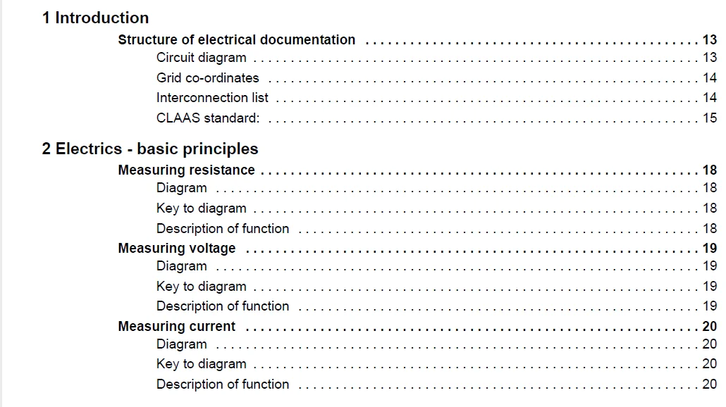
1 Introduction
Structure of electrical documentation 13
Circuit diagram 13
Grid co-ordinates 14
Interconnection list 14
CLAAS standard: 15
2 Electrics – basic principles
Measuring resistance 18
Diagram 18
Key to diagram 18
Description of function 18
Measuring voltage 19
Diagram 19
Key to diagram 19
Description of function 19
Measuring current 20
Diagram 20
Key to diagram 20
Description of function 20
3 Hydraulics – basic principles
Hydraulic pressure in motionless liquids 22
Diagram 1 22
Key to diagram 22
General principles: 23
Hydraulic pressure in moving liquids 24
Diagram 1 24
Key to diagram 24
Diagram 2 25
Key to diagram 25
General principles: 26
Hydraulic flow quantity 28
Diagram 28
Key to diagram 28
General principles: 29
Measuring pressure 30
Diagram 30
Key to diagram 30
General principles: 30
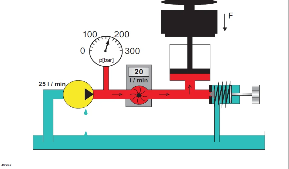
Measuring flow quantity 31
Diagram 31
Key to diagram 31
Description of function 31
Graphic symbols in fluidics 32
Graphic symbols and explanations 32
4 000 295 254 1 – SYS-E XERION 3300 – 12/07
32301
4 Central terminal compartment
Central terminal compartment 0599 998 0 (from serial no 322) 41
Circuit diagram (DIN A3) 42
Electronic components 43
Modules 43
Fuses 44
Relay 47
5 Modules
Module representation 51
Overview 1 52
Overview 2 53
Overview 3 54
Module pin assignment 55
Module A006 – automatic climate control 55
Module A007 – cab fan governor 57
Module A015 – electronic engine control CAT 58
Module A030 – Terminal Cebis 60
Module A033 – Sidefinder / Pathfinder module 62
Module A055 electro-hydraulic steering module (EHL) plug 1 63
Module A055 electro-hydraulic steering module (EHL) plug 2 66
Module A056 – VDC (vehicle drive control) 72
Module A057 – gearshift control (TCU) 77
Module A058 – lift control (eHR) 82
Module A059-1 valve control (VCU) 84
Module A059-2 – valve control (VCU) 86
Module A060 – hydraulic control unit (HYD) 88
Module A061 – fieldwork computer XERION (XIF) 93
Module A061 – fieldwork computer XERION (XIF)/with rear PTO shaft (automatic) 98
Module A062 – external control (EXT) 102
Module A066 – GPS Pilot (GPM) 105
Module A070 – power hydraulics (PHM) 106
6 Circuit diagrams
01a Main power supply, diesel engine electric starting motor 109
Circuit diagram (DIN A3) 110
Key to diagram 111
Description of function 111
Diagnosis table 1 111
Connector pin assignment 112
Interconnection list 112
02a Starting the diesel engine, diesel engine speed adjustment 113
Circuit diagram (DIN A3) 114
Key to diagram 115
Description of function 115
Electronic throttle switching logics 117
Diagnosis table 2a 117
Connector pin assignment 119
000 295 254 1 – SYS-E XERION 3300 – 12/07 5
32301
Interconnection list 119
03a Diesel engine cut-off system 121
Circuit diagram (DIN A3) 122
Key to diagram 123
Measuring value table 123
Description of function 123
Diagnosis table 3 124
Connector pin assignment 124
Interconnection list 124
04a Road travel circuit, constant pressure circuit 125
Circuit diagram (DIN A3) 126
Key to diagram 127
Measuring value table 127
Description of function 128
Diagnosis table 4 129
Connector pin assignment 130
Interconnection list 130
05a Terminal 131
Circuit diagram (DIN A3) 132
Key to diagram 133
Description of function 133
Connector pin assignment 134
Interconnection list 134
06a CAN bus, module power supply 135
Circuit diagram (DIN A3) 136
Key to diagram 137
Description of function 138
CAN bus network 139
Measured value table 250 kB vehicle CAN bus (Vehicle CAN bus) 139
Measured value table 250 kB CAN bus hydraulic system 139
Measured value table J1939 CAN bus 140
Measured value table ISO 11783 CAN bus 140
Connector pin assignment 141
Interconnection list 141
07a Rear PTO shaft circuit 145
Circuit diagram (DIN A3) 146
Key to diagram 147
Measuring value table 147
Description of function 148
Logics table: Rear PTO switch S114 (internal, in cab) 149
Logics table: Rear PTO switch U30 (external, on mud guard) 149
Diagnosis table 7 149
Connector pin assignment 151
Interconnection list 151
08a PTO shaft circuit II Auxiliary power take-off / power hydraulics 153
Circuit diagram (DIN A3) 154
Key to diagram 155
Measuring value table 155
6 000 295 254 1 – SYS-E XERION 3300 – 12/07
32301
Description of function 155
Logic table: PTO 2 auxiliary power take-off switch S113 157
Diagnosis table 8 157
Connector pin assignment 159
Interconnection list 159
09a External operation (EXT module) 161
Circuit diagram (DIN A3) 162
Key to diagram 163
Description of function 163
Diagnosis table 9 163
Connector pin assignment 165
10a ISO terminal, ISO operation 167
Circuit diagram (DIN A3) 168
Key to diagram 169
Description of function 169
Diagnosis table 10 170
Interconnection list 170
11a ISO signal socket 173
Circuit diagram (DIN A3) 174
Key to diagram 175
Description of function 175
Diagnosis table 11 175
Connector pin assignment 176
Interconnection list 176
12a Programmable functions (F keys) 177
Circuit diagram (DIN A3) 178
Key to diagram 179
A52 Multifunction handle module 179
Description of function 180
Diagnosis table 12 180
Connector pin assignment 181
Interconnection list 181
13a Connection of semi-mounted implements 183
Circuit diagram (DIN A3) 184
Key to diagram 185
Description of function 185
Connector pin assignment 186
Interconnection list 186
14a Three-point braces 187
Circuit diagram (DIN A3) 188
Key to diagram 189
Description of function 189
Diagnosis table 14 190
Connector pin assignment 191
Interconnection list 191
15a Tail PTO shaft engaging (automatic) 193
Circuit diagram (DIN A3) 194
Key to diagram 195
000 295 254 1 – SYS-E XERION 3300 – 12/07 7
32301
Measuring value table 195
Description of function 196
Diagnosis table 15 198
Connector pin assignment 200
Interconnection list 200
20a Front hydraulics 201
Circuit diagram (DIN A3) 202
Key to diagram 203
A52 Multifunction handle module 204
Measuring value table 204
Description of function 205
Diagnosis table 20 206
Connector pin assignment 208
Interconnection list 208
21a Tail hydraulics EHR 209
Circuit diagram (DIN A3) 210
Key to diagram 211
A52 Multifunction handle module 212
Measuring value table 212
Description of function 212
Diagnosis table 21 216
Connector pin assignment 217
Interconnection list 218
22a Service valves, additional control units 219
Circuit diagram (DIN A3) 220
Key to diagram 221
Measuring value table 222
Description of function 222
Diagnosis table 22 223
Connector pin assignment 225
Interconnection list 225
23a Blue service valve 227
Circuit diagram (DIN A3) 228
Key to diagram 229
Measuring value table 229
Description of function 230
Diagnosis table 23 230
Connector pin assignment 231
Interconnection list 231
26a Machine monitoring (hydraulics) 233
Circuit diagram (DIN A3) 234
Key to diagram 235
Measuring value table 235
Description of function 236
Diagnosis table 26 237
Connector pin assignment 239
Interconnection list 239
8 000 295 254 1 – SYS-E XERION 3300 – 12/07
32301
28a EHL (Autopilot), Cab position identification 241
Circuit diagram (DIN A3) 242
Key to diagram 243
Measuring value table 244
Description of function 246
Logics table: Emergency steering pump monitoring 249
Logics table: Cab position identification 249
Diagnosis table 28 249
Connector pin assignment 252
Interconnection list 252
30a Warning beacon 255
Circuit diagram (DIN A3) 256
Key to diagram 257
Description of function 257
Connector pin assignment 257
Interconnection list 257
31a Locking the floating axle 259
Circuit diagram (DIN A3) 260
Key to diagram 261
Measuring value table 261
Description of function 261
Diagnosis table 31 262
Connector pin assignment 263
Interconnection list 263
32a Locking differentials 265
Circuit diagram (DIN A3) 266
Key to diagram 267
Measuring value table 267
Description of function 267
Diagnosis table 32 269
Connector pin assignment 270
Interconnection list 270
33a Cab rotation 271
Circuit diagram (DIN A3) 272
Key to diagram 273
Measuring value table 273
Description of function 274
Diagnosis table 33 275
Connector pin assignment 276
Interconnection list 276
36a Turn indicator system (Europe) 277
Circuit diagram (DIN A3) 278
Key to diagram 279
Description of function 281
Diagnosis table 36 281
Connector pin assignment 282
Interconnection list 282
000 295 254 1 – SYS-E XERION 3300 – 12/07 9
32301
36b Turn indicator system (USA) 283
Circuit diagram (DIN A3) 284
Key to diagram 285
Description of function 287
Diagnosis table 36 287
Connector pin assignment 288
Interconnection list 288
37a Windscreen wiper, Windscreen washer 289
Circuit diagram (DIN A3) 290
Key to diagram 291
Description of function 291
Connector pin assignment 291
Interconnection list 292
38a Automatic air conditioner 293
Circuit diagram (DIN A3) 294
Key to diagram 295
Measuring value table 296
Discription of function 297
Connector pin assignment 303
Interconnection list 303
39a Operator’s seat 305
Circuit diagram (DIN A3) 306
Key to diagram 307
Description of function 307
Connector pin assignment 307
Interconnection list 307
40a Additional sockets 309
Circuit diagram (DIN A3) 310
Key to diagram 311
Description of function 311
Connector pin assignment 311
Interconnection list 311
41a Drive management, brake, parking brake 313
Circuit diagram (DIN A3) 314
Key to diagram 315
Measuring value table 316
Description of function 317
Diagnosis table 41 320
Connector pin assignment 322
Interconnection list 322
42a Limp Home 325
Circuit diagram (DIN A3) 326
Key to diagram 327
Description of function 327
Diagnosis table 42 328
Connector pin assignment 328
Interconnection list 328
10 000 295 254 1 – SYS-E XERION 3300 – 12/07
32301
43a Trailer brake, central lubrication system 329
Circuit diagram (DIN A3) 330
Key to diagram 331
Measuring value table 332
Description of function 332
Diagnosis table 43 333
Connector pin assignment 333
Interconnection list 333
44a Transmission control 335
Circuit diagram (DIN A3) 336
Key to diagram 337
Measuring value table 338
Description of function 338
Diagnosis table 44 339
Connector pin assignment 341
Interconnection list 341
45a Lighting main circuit, taillight, position light 343
Circuit diagram (DIN A3) 344
Key to diagram 345
Description of function 345
Connector pin assignment 346
Interconnection list 346
46a Low beam, high beam, low beam changeover switch 347
Circuit diagram (DIN A3) 348
Key to diagram 349
Description of function 350
Connector pin assignment 350
Interconnection list 350
47a Worklights I 353
Circuit diagram (DIN A3) 354
Key to diagram 355
Description of function 356
Diagnosis table 47 356
Connector pin assignment 356
Interconnection list 356
48a Worklights II 359
Circuit diagram (DIN A3) 360
Key to diagram 361
Description of function 362
Connector pin assignment 362
Interconnection list 362
49a Horn, brake light, back-up light 363
Circuit diagram (DIN A3) 364
Key to diagram 365
Description of function 366
Diagnosis table 49 366
Connector pin assignment 366
Interconnection list 366
000 295 254 1 – SYS-E XERION 3300 – 12/07 11
32301
50a Instrument lighting, broadcast radio, mirror adjustment 369
Circuit diagram (DIN A3) 370
Key to diagram 371
Description of function 372
Connector pin assignment 372
Interconnection list 372
7 Diagnosis
Diagnosis according to fault codes 373
Fault code CCN (CLAAS Component Number) 373
FMI (Failure Mode Indicator) 384
List 384
8 Location of components
Overview (DIN A3) 393
Figures 393
IMAGES PREVIEW OF THE MANUAL:
CLAAS XERION 3300 XERION 3800 TECHNICAL SYSTEMS ELECTRIC SYSTEM MANUAL – PDF DOWNLOAD:
PLEASE NOTE:
- This is the SAME MANUAL used by the dealerships to diagnose your vehicle
- No waiting for couriers / posts as this is a PDF manual and you can download it within 2 minutes time once you make the payment.
- Your payment is all safe and the delivery of the manual is INSTANT – You will be taken to the DOWNLOAD PAGE.
- So have no hesitations whatsoever and write to us about any queries you may have : heydownloadss @gmail.com
S.V