CLARK FORKLIFT CGP I CDP 16-50 H Hydrostatic Transmission SERVICE MANUAL
Original price was: $76.95.$27.95Current price is: $27.95.
CLARK FORKLIFT CGP I CDP 16 50 H Hydrostatic Transmission SERVICE MANUAL – PDF DOWNLOAD
Description
CLARK FORKLIFT CGP I CDP 16 50 H Hydrostatic Transmission SERVICE MANUAL – PDF DOWNLOAD
Customer Support: [email protected]
Image Preview:
![]()
![]()
![]()
Description:
CLARK FORKLIFT CGP I CDP 16 50 H Hydrostatic Transmission SERVICE MANUAL – PDF DOWNLOAD
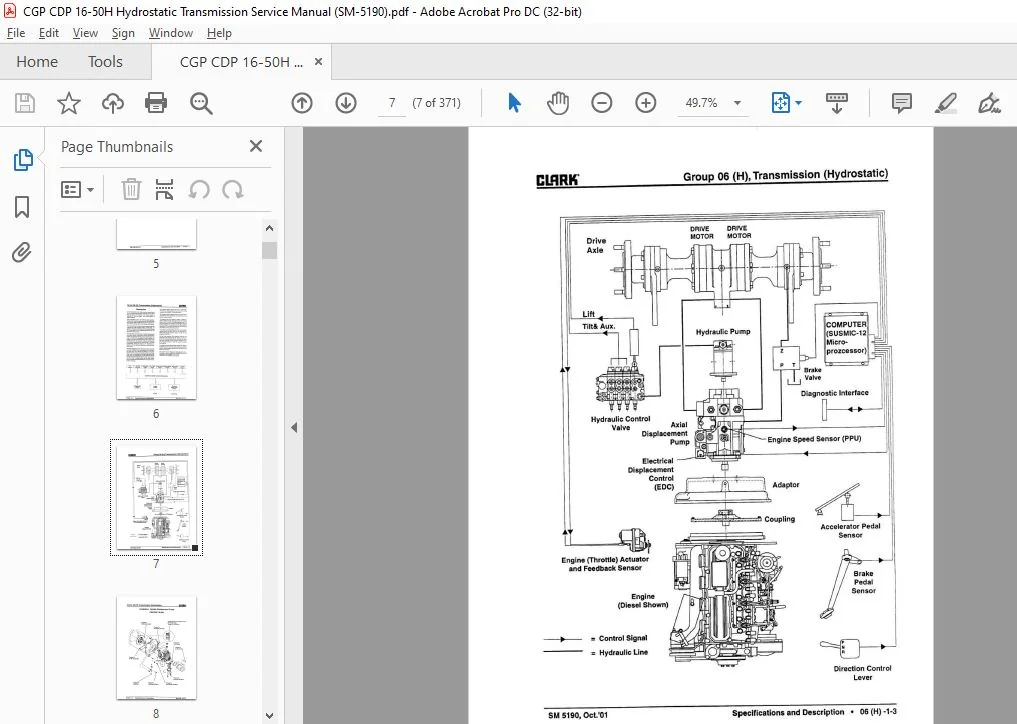
- In the hydrostatic drive truck, power is transmitted to the drive wheels by hydraulic-powered motors, rather than by gears and clutches. The entire system is depicted on the next page. The control system is depicted below.
- The hydrostatic truck’s conventional spark-ignited or diesel engine rotates a hydraulic pump, the “hydrostatic drive pump,• that supplies fluid to two hydraulic motors in the drive axle. Each motor drives a drive wheel.
- The hydraulic fluid is drawn from the same sump that supplies the load handling system. [Incidentally, the pump for the load-handling system (covered in Group 29) is mounted on, and mechanically driven by, the hydrostatic drive pump.]
- The hydrostatic drive pump is a variable displacement axial piston pump. Pump output volume and direction of flow are governed by the pump’s swashplate. The angle at which the swashplate is tilted controls the length of the piston strokes as the pistons rotate past inlet/outlet ports. Swashplate angle is controlled by an electrical displacement control (EDC). The EDC hydraulically varies the angle of the swashplate in response to the electrical signal level received from the comput The fluid displaced by the drive pump flows through external plumbing to the radial piston drive motors in the drive axle.
- The volume and direction of the fluid determines the speed and direction of the truck. Each drive motor is connected to an axle shaft that drives an axle end and wheel identical to those used on the standard truck. Parallel circuitry to the drive motors allows a speed differential between the motors when the
truck is cornering.The diagram below shows the flow of information into and out of the computer that controls the drive system-the SUSMIC 12 microprocessor. The inputs consist of signals from the various sensors and switches that are affected by positioning of the truck’s manual controls. - The signals from the switches consist of either an open or closed circuit. The signal from the engine speed sensor consists of pulses ranging from 0 to 9.9 kHz (cycles per second), increasing as engine speed increases.
- The signals from the other sensors consists of 0 to 5-volt levels that vary according to the position of the associated control. The outputs consists of electrical power to the engine actuator and to the EDC. Zero to 12 volts are supplied to the engine actuator and 0 lo 100 mA are supplied to the EDC. As the truck operates, the computer monitors the positions of the various manual controls in order to sense the desired performance; while at the same time, the computer monitors engine speed and engine actuator position in order to sense the actual performance.
- To make the actual performance match the desired performance, the computer varies the engine throttle position via the engine actuator and the drive pump output via the EDC. The system can be diagnosed and adjusted with a diagnostic control, usually the SUSMIC-DIA 3, that connects to the SUSMIC 12 computer
Table Of Contents:
CLARK FORKLIFT CGP I CDP 16 50 H Hydrostatic Transmission SERVICE MANUAL – PDF DOWNLOAD
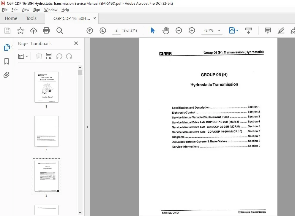
Specification and Description …………………………………………. Section 1
Elektronic-Control …………………………………………………………… Section 2
Service Manual Variable Displacement Pump ..•••..•…………… Section 3
Service Manual Drive Axle CDP/CGP 16-20H (MCR 3) •……… Section 4
Service Manual Drive Axle CDP/CGP 20-35H (MCR 5) .•…..•. Section 5
Service Manual Drive Axle CDP/CGP 40-S0H (MCR 10) •….. Section 6
Diagrams ………………………………………………………………………… Section 7
Actuators-Throttle Goveror & Brake Valves ……….•……………. Section 8
Service-Informations ..•….••…•••••…..•……•.•………………..•……….. Section 9
Please Note:
- This is not a physical manual but a digital manual – meaning no physical copy will be couriered to you. The manual can be yours in the next 2 mins as once you make the payment, you will be directed to the download page IMMEDIATELY.
- This is the same manual used by the dealers inorder to diagnose your vehicle of its faults.
- Require some other service manual or have any queries: please WRITE to us at [email protected]