Trusted Business
Verified & Licensed
Virus Free Files
100% Safe Downloads
Secure Payment
SSL Protected
Instant Delivery
Available Immediately
Sale!


CLARK FORKLIFT SM 622 CDP 100164 SERVICE MANUAL
Original price was: $65.95.$25.95Current price is: $25.95.
CLARK FORKLIFT SM 622 CDP 100164 SERVICE MANUAL – PDF DOWNLOAD
Instant PDF Download
Available immediately
Save to Your Device
Download & keep forever
Antivirus Scanned
100% virus-free
Trusted Worldwide
175,000+ customers
Description
CLARK FORKLIFT SM 622 CDP 100164 SERVICE MANUAL – PDF DOWNLOAD
Customer Support: [email protected]
Image Preview:


Description:
CLARK FORKLIFT SM 622 CDP 100164 SERVICE MANUAL – PDF DOWNLOAD
- Proper maintenance and care are essential if your Clark truck is to be always ready for use. These preventative maintenance procedures provide a basic guide which should be followed when servicing your Clark truck.
- A lubrication guide and recommended preventative maintenance program is included in this section and for further information regarding adjustment procedures, specifications, etc., please refer to the index in the front of this manual. IMPORTANT Your Clark dealer has both the facilities, parts, and adequately trained personnel enabling them to carry out all necessary service procedures, including complete inspections, maintenance and lubrication programs, all aimed at ensuring your Clark Lift truck will perform safety and efficiently and most importantly, maximizing its availability for your day to day work schedules.
- RECOMMENDED MAINTENANCE PROCEDURE Particular attention should be paid to the conditions under which your CDP 100/164 forklift truck is used as those conditions play a significant role in determining how long the interval between each maintenance task should be.
- It is quite clear that a truck used in sandy, dusty, dirty locations will require more frequent maintenance than one being used in a clean warehouse situation. The maintenance schedules and recommendations made in this book apply for use under normal operating conditions.
- The following classifies the different types of operating conditions.. Class 1 – Normal conditions of use Basically transfer and loading of goods and materials for eight hours per day in buildings or in the open air.
Table Of Contents:
CLARK FORKLIFT SM 622 CDP 100164 SERVICE MANUAL – PDF DOWNLOAD
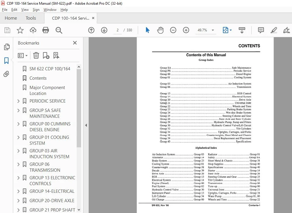
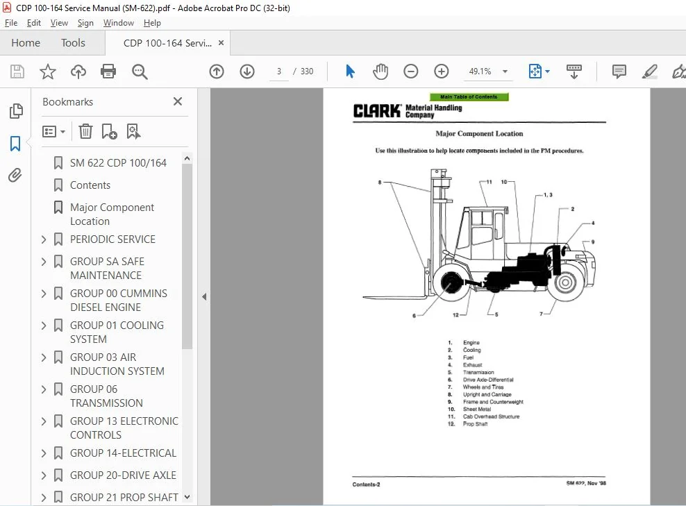
SM 622 CDP 100/164.........................................................................................  1
Contents...................................................................................................  2
Major Component Location...................................................................................  3
PERIODIC SERVICE...........................................................................................  4
	Section 1. INTRODUCTION................................................................................  5
	Section 2. Lift Truck Maintenance......................................................................  8
		ACCUMULATORS....................................................................................... 21
		Air Brakes......................................................................................... 18
		Air Brakes Adjustment.............................................................................. 20
		Air Pressure Gauge................................................................................. 17
		Batteries.......................................................................................... 19
		Carriage and Upright Load Rollers.................................................................. 23
		Carriage Side Thrust Rollers....................................................................... 23
		Checks with the engine running..................................................................... 18
		Cleaning........................................................................................... 22
		Container Handling Attachments..................................................................... 22
		Critical Fastener Torque Checks.................................................................... 22
		Daily Check Lift...................................................................................  9
		Differential Oil and Breather Check................................................................ 21
		Engine Accessories................................................................................. 19
		Engine Air Cleaner................................................................................. 19
		Engine Cooling System.............................................................................. 19
		Engine Oil......................................................................................... 20
		Engine Oil and Filter Change....................................................................... 20
		Fluid and Filters.................................................................................. 19
		Forks.............................................................................................. 16
		Fork Tynes......................................................................................... 22
		Functional Tests................................................................................... 17
		HOW TO PERFORM PLANNED MAINTENANCE................................................................. 16
		Hour Meter......................................................................................... 17
		Hydraulic System................................................................................... 21
		Hydraulic Tank..................................................................................... 21
		Hydraulic Tank Breather Maintenance and Inspection................................................. 21
		Key/Start Switch................................................................................... 17
		Lift Chains........................................................................................ 22
		Lift Chain Maintenance............................................................................. 22
		Lift Chain Adjustment Check........................................................................ 22
		Lift Chain Inspection and Measurement.............................................................. 23
		Lift Mechanisms and Controls....................................................................... 18
		NAMEPLATES & DECALS................................................................................ 16
		Operating Conditions...............................................................................  9
		Preventative Maintenance Schedule.................................................................. 12
		PLANNED MAINTENANCE REPORT......................................................................... 14
		Planned Maintenance................................................................................  9
		Planned Maintenance Program........................................................................ 16
		PM Program......................................................................................... 16
		Radiator........................................................................................... 20
		Scaffolds and Work Platforms....................................................................... 23
		Steering System.................................................................................... 18
		Shift Control...................................................................................... 19
		Transmission Fluid Check........................................................................... 21
		Transmission Light................................................................................. 17
		Truck Chassis Inspection and Lubrication........................................................... 22
		Upright and Tilt Cylinder Lubrication.............................................................. 22
		Upright/Carriage Maintenance....................................................................... 23
		Water Temperature Gauge............................................................................ 17
		Wet Disc Brakes.................................................................................... 21
		Wet Disc Brakes.................................................................................... 18
		Wheels and Tires................................................................................... 17
		250 Hour Service Check list........................................................................ 11
GROUP SA SAFE MAINTENANCE.................................................................................. 24
	Section 1. Safety...................................................................................... 25
	Section 2. Lifting, Jacking, and Blocking.............................................................. 27
		Safe Parking....................................................................................... 28
		Lifting, Blocking, and Jacking Points.............................................................. 28
	Section 3. Towing...................................................................................... 29
GROUP 00 CUMMINS DIESEL ENGINE............................................................................. 30
	SECTION 1. TROUBLESHOOTING............................................................................. 31
	Section 2. Engine Removal and Replacement.............................................................. 42
		ENGINE REMOVAL..................................................................................... 43
	Section 3 Cumrnins Engine Specifications............................................................... 46
GROUP 01 COOLING SYSTEM.................................................................................... 47
	Troubleshooting........................................................................................ 48
	SECTION 2 TESTING AND MAINTENANCE...................................................................... 49
	SECTION 3 RADIATOR REPAIR.............................................................................. 52
GROUP 03 AIR INDUCTION SYSTEM.............................................................................. 53
	SECTION 1 AIR INTAKE and AIR CLEANER................................................................... 54
GROUP 06 TRANSMISSION...................................................................................... 55
	SECTION 1 SPECIFICATIONS & SERVICE DATA................................................................ 56
	SECTION 2 Troubleshooting.............................................................................. 59
	SECTION 3 TRANSMISSION COOLING......................................................................... 61
	SECTION 4 TRANSMISSION FILTER INSTALLATION............................................................. 62
	SECTION 5 28000 SERIES TRANSMISSION.................................................................... 63
		TOWING OR PUSH STARTING............................................................................ 65
		FOREWORD........................................................................................... 66
		TABLE OF CONTENTS.................................................................................. 67
		TRANSMISSION ASSEMBLY.............................................................................. 68
		HOW THE UNITS OPERATE.............................................................................. 69
		Sectional Views.................................................................................... 70
			FIGURE A....................................................................................... 70
			FIGURE B....................................................................................... 71
			HR 28000 CONVERTER GROUP....................................................................... 72
			FIGURE C....................................................................................... 73
			HR 28000 CONVERTER AND TRANSMISSION CASE GROUP................................................. 74
			FIGURE D....................................................................................... 75
			28000 THREE-SPEED CASE AND CLUTCH GROUP........................................................ 76
			FIGURE E....................................................................................... 77
			LOW CLUTCH GROUP............................................................................... 78
			REVERSE AND 3rd CLUTCH GROUP................................................................... 78
			FORWARD AND 2nd CLUTCH GROUP................................................................... 78
			FIGURE F....................................................................................... 79
			PRESSURE REGULATOR VALVE, CHARGING PUMP & OIL FILTER GROUP..................................... 80
			FIGURE G....................................................................................... 81
			CONTROL VALVE ASSEMBLY......................................................................... 82
			MECHANICAL PARKING BRAKE....................................................................... 83
			FIGURE H....................................................................................... 83
			FIGURE I....................................................................................... 84
			FIGURE J....................................................................................... 85
		MAINTENANCE AND SERVICE............................................................................ 86
			CLUTCH DISASSEMBLY............................................................................. 94
			LOW CLUTCH DISASSEMBLY......................................................................... 94
			FORWARD &2ND CLUTCH DISASSEMBLY................................................................ 96
		CLEANING AND INSPECTION............................................................................ 97
			CLEANING....................................................................................... 97
			INSPECTION..................................................................................... 98
			REASSEMBLY..................................................................................... 98
		LOW CLUTCH REASSEMBLY..............................................................................100
		SERVICING MACHINE AFTER TRANSMISSION OVERHAUL......................................................111
		SPECIFICATIONS AND SERVICE DATA-...................................................................112
		LUBRICATION........................................................................................112
		TROUBLE SHOOTING GUIDE.............................................................................113
		3 SPEED TRANSMISSION...............................................................................114
		28000 SERIES - 3 SPEED CLUTCH & GEAR ARRANGEMENT...................................................115
			MODULATED FWD. & REV. CLUTCHES.................................................................116
		SHIELDED BEARING INSTALLATION......................................................................117
		16 SCREW RING GEAR INSTALLATION PROCEDURE..........................................................119
		32 SCREW RING GEAR INSTALLATION PROCEDURE..........................................................121
		SPEED SENSOR BUSHING INSTALLATION..................................................................123
		PROPER INSTALLATION OF TEFLON PISTON RING AND PISTON RING EXPANDER SPRINGS.........................124
		DRIVE PLATE INSTALLATION...........................................................................125
		TRANSMISSION TO ENGINE INSTALLATION PROCEDURE......................................................126
		28000/32000 SERIES TRANSMISSION AND C-270/C-320 CONVERTER DRIVE PLATE INSTALLATION INSTRUCTIONS....127
		TRANSMISSION TO ENGINE INSTALLATION PROCEDURE......................................................128
		DRIVE GEAR REPLACEMENT PROCEDURE...................................................................129
		NON-ASBESTOS THIRTYTWO (32) BOLT TORQUE CONVERTER DRIVE RING GEAR..................................131
		TORQUE CONVERTER DRIVE GEAR INSTALLATION...........................................................133
			DIMEMSIONAL VALUES.............................................................................135
			INSPECTION OF IMPELLER COVER GEAR TEETH........................................................136
			ENGINE FLYWHEEL AND FLYWHEEL HOUSING INSPECTION PROCEDURE......................................137
			FLYWHEEL HOUSING RUNOUT........................................................................137
			FLYWHEEL HOUSING BORE..........................................................................138
			CHARTFOFtDlALlNDlCATOR.........................................................................139
			FLYWHEEL RUNOUT................................................................................140
			Eccentricity - Drive Gear to Nose Pilot........................................................141
GROUP 13 ELECTRONIC CONTROLS...............................................................................142
	SECTION 1 PROTECTIVE SYSTEMS...........................................................................143
	SECTION 2 EGS USER MANUAL AND TROUBLESHOOTING GUIDE....................................................144
		PRODUCT DEFINITION.................................................................................145
		FUNCTION DESCRIPTION...............................................................................145
		USER INTERFACE.....................................................................................145
			SHIFT LEVER OPERATION..........................................................................145
				GRIP TYPE OPERATION........................................................................145
				STANDARD TYPE OPERATION....................................................................145
			STANDARD FEATURES..............................................................................146
				AUTOMATIC POWERUP IN NEUTRAL...............................................................146
				NEUTRAL START PROTECTION...................................................................146
				SHIFT REPEAT...............................................................................146
			EXTERNAL INPUTS................................................................................146
			DISPLAY FUNCTION...............................................................................146
				DISPLAYED INFORMATION......................................................................146
					SELECTED POSITION......................................................................146
					APPLICATION SPECIFIC INFORMATION.......................................................146
					DIAGNOSTIC INFORMATION.................................................................146
				DISPLAY LAYOUT.............................................................................147
				DISPLAY METHOD.............................................................................147
		OVERRIDE SYSTEM....................................................................................147
		EGS LED’S FUNCTION.................................................................................148
			GENERAL DISPLAY INFORMATION....................................................................148
			N LED..........................................................................................148
			T LED..........................................................................................148
			LED 1 THROUGH 6................................................................................148
			LED 7..........................................................................................148
			LED 8..........................................................................................148
			POWER UP CONDITION.............................................................................148
			TO GET DRIVE...................................................................................148
		SELFTEST FUNCTIONS.................................................................................148
			SELFTEST OPERATION.............................................................................148
			OPERATION OF THE “N” AND “T” LEDs..............................................................149
				OVERVIEW...................................................................................149
				DETAILED OPERATION.........................................................................149
				INPUT TEST.................................................................................149
				SPEED SENSOR TEST..........................................................................149
				LAMPTEST...................................................................................149
				SPEED DISPLAY..............................................................................149
				OUTPUT TEST................................................................................149
	SECTION 3 How to Use Battery Jumper Cables.............................................................150
GROUP 14-ELECTRICAL........................................................................................152
	Section 1 General Troubleshooting......................................................................153
	Section 2 Starter and Battery Troubleshooting..........................................................154
		General Information................................................................................154
		Minimum Tools Required.............................................................................154
		Starting System Inspection.........................................................................155
		Electrical Checks..................................................................................156
			Slow or Sluggish Cranking......................................................................156
			Nothing Happens When Start Attempt Is Made.....................................................157
		Volt Drop Tests....................................................................................159
	Section 3 Alternator Troubleshooting...................................................................162
		Alternator Maintenance Precautions.................................................................162
		Troubleshooting Procedures.........................................................................163
			Abnormal Operation (Negative Reading) of the Ammeter...........................................164
		Symptoms, Causes, and Remedies.....................................................................164
	SECTION 4 Alternator Overhaul..........................................................................165
		FEATURES...........................................................................................167
		CONTENTS...........................................................................................168
		INTRODUCTION.......................................................................................168
		FEATURES...........................................................................................169
		OPERATING PRINCIPLES...............................................................................170
		TROUBLESHOOTING....................................................................................171
			ALL CHARGING SYSTEMS...........................................................................171
			SYSTEMS WITH INDICATOR LIGHT...................................................................171
			SYSTEMS WITHOUT INDICATOR LIGHT................................................................172
			NO OUTPUT......................................................................................173
			RATED OUTPUT CHECK.............................................................................173
		GENERATOR UNIT REPAIR..............................................................................175
			DISASSEMBLY AND BENCH CHECKS...................................................................175
				GENERATOR..................................................................................175
				SRE HOUSING AND COMPONENTS.................................................................175
					Electrical Check of Stator.............................................................176
					Electrical Check of Diode Trio.........................................................176
					Electrical Check of Rectifier Bridge...................................................176
				DE FRAME AND COMPONENTS....................................................................177
					Electrical Check of Rotor..............................................................178
			GENERATOR ASSEMBLY.............................................................................178
				ASSEMBLY OF DE FRAME AND COMPONENTS........................................................178
				ASSEMBLY OF SRE HOUSING AND COMPONENTS.....................................................178
					Installing Rectifier Bridge............................................................179
					Installing Relay Terminal..............................................................179
					Installing BAT Terminal and Capacitor..................................................179
					Installing Regulator...................................................................180
					Assembly of Brush Holder...............................................................180
					Installing Brush Holder and Diode Trio.................................................180
					Regulator Connector, l-Wire System.....................................................180
					Regulator Connector, 3-wire System.....................................................181
					Fastener Tightening Order..............................................................181
					Installing Stator......................................................................181
				FINAL UNIT ASSEMBLY........................................................................182
					Cleaning Slip Rings....................................................................182
					Removal of Brush Pin...................................................................182
			GENERATOR BENCH TEST...........................................................................183
		GENERATOR MOUNTING.................................................................................185
		SERVICE PARTS......................................................................................187
		Generator Specifications...........................................................................188
	SECTION 5 Starter Troubleshooting......................................................................189
		CRANKING MOTORS....................................................................................190
		MAINTENANCE........................................................................................190
		ADJUSTABLE NOSE HOUSING............................................................................190
		OPERATION..........................................................................................190
		Cross-sectional view,..............................................................................191
		TROUBLESHOOTING THE CRANKING CIRCUIT...............................................................192
		DISASSEMBLY........................................................................................193
		CLEANING...........................................................................................193
		ARMATURE SERVICING.................................................................................194
		FIELD COIL CHECKS..................................................................................195
		FIELD COIL REMOVAL.................................................................................195
		SOLENOID CHECKS....................................................................................195
		THREE-TERMINAL SOLENOID............................................................................195
		FOUR-TERMINAL SOLENOID.............................................................................196
		REASSEMBLY.........................................................................................196
		LUBRICATION........................................................................................196
		PINION CLEARANCE...................................................................................196
		PINION CLEARANCE...................................................................................197
	SECTION 6 Wiring Diagrams SM622 Section Title Page Nov ‘98.............................................198
	SECTION 7 ELECTRICAL TOOLS.............................................................................203
GROUP 20-DRIVE AXLE........................................................................................205
	SECTION  1 Troubleshooting.............................................................................206
	SECTION 2 DRIVE AXLE Overhaul..........................................................................208
		Index..............................................................................................210
		AXLE DESIGN........................................................................................211
		WHEEL HUBS.........................................................................................212
			Removal:.......................................................................................212
			Dismantling:...................................................................................213
			Assembly:......................................................................................214
			Wheel hub bearing adjustment:..................................................................214
			Half shaft inspection and installation:........................................................214
			Assembly of planetary carrier..................................................................214
			Installation of planetary carrier..............................................................215
		DRIVE GEAR.........................................................................................216
		DIFFERENTIAL LOCK..................................................................................216
		DIFFERENTIAL.......................................................................................217
		PINION UNIT........................................................................................218
			Dismantling....................................................................................218
			Assembly.......................................................................................219
		DIFFERENTIAL.......................................................................................221
		DRIVE GEAR.........................................................................................222
		REPLACEMENT OF PINION I CROWN WHEEL ASSEMSLY.......................................................223
		INSTALLATION OF THE DRIVE GEAR.....................................................................225
		SPECIAL TOOLS......................................................................................226
		TIGHTENING TORQUES.................................................................................226
		LUBRICATION........................................................................................226
		AXLE CHARACTERISTICS AND DATA......................................................................226
GROUP 21 PROP SHAFT........................................................................................227
	Section 1 Troubleshooting..............................................................................228
	Section 2 Prop Shaft Removal and Repair................................................................229
GROUP 22 TIRE AND WHEEL SAFETY.............................................................................231
	Pneumatic Wheels and Tires.............................................................................232
	Pneumatic Tire Maintenance Precaution..................................................................233
	General Tire Maintenance, Inspection, and Repair.......................................................234
	Wheel Dismounting and Remounting.......................................................................235
	Wheel Disassembly and Tire Removal.....................................................................235
	Tire Replacement and Wheel Reassembly..................................................................237
		Tire-to-Wheel Mounting.............................................................................238
		Filling Tires with Air.............................................................................239
		Installing to Truck................................................................................239
GROUP 23 PARKING BRAKES....................................................................................240
GROUP 24 SERVICE BRAKES....................................................................................242
	Contents...............................................................................................244
	Cross-section of WDB brake assembly....................................................................245
	Brake Maintenance......................................................................................246
	Brake Dismantling......................................................................................246
	Wheel Hub Seal Replacement.............................................................................246
	Install the Wheel Hub/Brake Adapter as Follows:........................................................247
	Hub Inner Seal Installation Details....................................................................248
	Sleeve Ring Installation...............................................................................248
	Brake Dismantling......................................................................................250
	Brake Cover/Piston Inspections.........................................................................251
	Brake Drum Dismantling.................................................................................251
	Brake Plate Installation...............................................................................252
	Brake Unit Installation................................................................................253
	Brake Back Plate, Piston and Piston Seal Replacement Details...........................................255
	Outer Hub Seal Replacement.............................................................................256
	Seal Installation......................................................................................256
	Brake Plate Centering Tools in Position................................................................258
	Special Tools..........................................................................................259
GROUP 25 STEERING..........................................................................................260
	Steering Section 1. S.T.A.C. and Accumulator Charge Valve..............................................260
		Steering Valve.....................................................................................261
		GENERAL............................................................................................262
		SAFETY.............................................................................................262
		FUNCTION TESTING...................................................................................262
		DISMANTLING........................................................................................263
		INSPECTION.........................................................................................263
		RE-ASSEMBLY........................................................................................263
		RE-TEST............................................................................................263
Group 26. Steer Axle.......................................................................................264
	General Description....................................................................................264
	Steer Axle Stop Adjustment.............................................................................264
	MAINTENANCE PROCEDURES.................................................................................264
		Removal............................................................................................264
		Installation.......................................................................................264
	STEERING CYLINDER......................................................................................265
		Removal............................................................................................265
		Inspection.........................................................................................265
		Assembly...........................................................................................265
		Installation.......................................................................................265
	Wheel Bearing and Pivof Bearing Adjustment.............................................................265
GROUP30 HYDRAULICS.........................................................................................266
	Section 1 Hydraulic Schematic..........................................................................267
	Section 2 Control Valve................................................................................268
		REPLACING, ADDING OR REMOVING SECTION..............................................................269
		REPLACING SPOOL SEALS..............................................................................270
		REPLACING, ADDING OR REMOVING WORK SECTION ASSEMBLIES..............................................271
		REPLACING SPOOL SEALS..............................................................................272
	Section 3 TANDEM COOLING PUMPS.........................................................................273
		single gear pump introduction......................................................................275
		Index..............................................................................................276
		Tools required.....................................................................................276
		Preparation for disassembly........................................................................278
		Disassembly........................................................................................280
		Service inspection.................................................................................284
		Reassembly.........................................................................................288
		Break-in of repaired pumps.........................................................................295
		Hydraulic system maintenance.......................................................................295
		TROUBLESHOOTING....................................................................................296
GROUP 32 TILT CYLINDER.....................................................................................297
	Section 1 Tilt Cylinder Service Procedures.............................................................298
		Disassembly........................................................................................300
		Cleaning & Inspection..............................................................................302
		Reassembly.........................................................................................303
		Seal Installation Tool.............................................................................304
	Section 2 Tilt Cylinder Drift Test.....................................................................307
	Section 3 Tilt Cylinder Adjustment.....................................................................309
GROUP34 UPRIGHT............................................................................................310
	Section 1 GENERAL DESCRIPTION..........................................................................311
		SAFETY PRECAUTIONS,................................................................................311
	Section 2 CARRIAGE AND UPRIGHT ROLLERS.................................................................312
		INTRODUCTION.......................................................................................312
		LOAD ROLLER ASSEMBLY...............................................................................312
		CARRAIGE THRUST ROLLERS............................................................................312
	Section 3. Upright Chain Inspection, Adjustment........................................................313
		Periodic Inspections...............................................................................314
		Chain Length Adjustments...........................................................................316
		Chain Removal and Replacement......................................................................320
		Chain Lubrication..................................................................................321
		Other Chain Service Notes..........................................................................321
Group 40, Specifications...................................................................................322
	Section 1. General Specifications......................................................................322
		Weights and Performance Specifications.............................................................323
			Capacities*....................................................................................323
			Truck weights..................................................................................323
			Maximum Grade..................................................................................323
			Parking Brake Test.............................................................................324
			Drawbar Pull Maximum...........................................................................324
			Travel Speeds..................................................................................324
			Turning Radius.................................................................................324
			Drift - Lift and Tilt Cylinders................................................................325
			Lift arid Lower Speeds. Utxiaht................................................................325
			Group Specifications...........................................................................325
Please Note:
- This is the SAME exact manual used by your dealers to fix your vehicle.
- The same can be yours in the next 2-3 mins as you will be directed to the download page immediately after paying for the manual.
- Any queries / doubts regarding your purchase, please feel free to contact [email protected]