Trusted Business
Verified & Licensed
Virus Free Files
100% Safe Downloads
Secure Payment
SSL Protected
Instant Delivery
Available Immediately
Sale!


CLARK FORKLIFT SM 648 CMP 404550S SERVICE MANUAL
Original price was: $71.95.$26.95Current price is: $26.95.
CLARK FORKLIFT SM 648 CMP 404550S SERVICE MANUAL – PDF DOWNLOAD
Instant PDF Download
Available immediately
Save to Your Device
Download & keep forever
Antivirus Scanned
100% virus-free
Trusted Worldwide
175,000+ customers
Description
CLARK FORKLIFT SM 648 CMP 404550S SERVICE MANUAL – PDF DOWNLOAD
Customer Support: [email protected]
Image Preview:
Description:
CLARK FORKLIFT SM 648 CMP 404550S SERVICE MANUAL – PDF DOWNLOAD
- Operation of the truck to check performance must be conducted in an authorized, safe, clear area. Before starting to drive truck: a. Be in operating position. b. Be sure parking brake is engaged. c. Put direction control in neutral. d. Start engine. e. Check functioning of direction and speed controls, steering, brakes, warning devices, and any load handling attachments. 19. 20. 21.
- Modifications and additions that affect capacity and safe truck operation must not be done without the manufacturer’s prior written approval. Capacity, operation and maintenance instruction plates, tags, or decals must be changed accordingly. This is an OSHA requirement. Before leaving truck a. Stop truck. b. Put directional control in neutral.
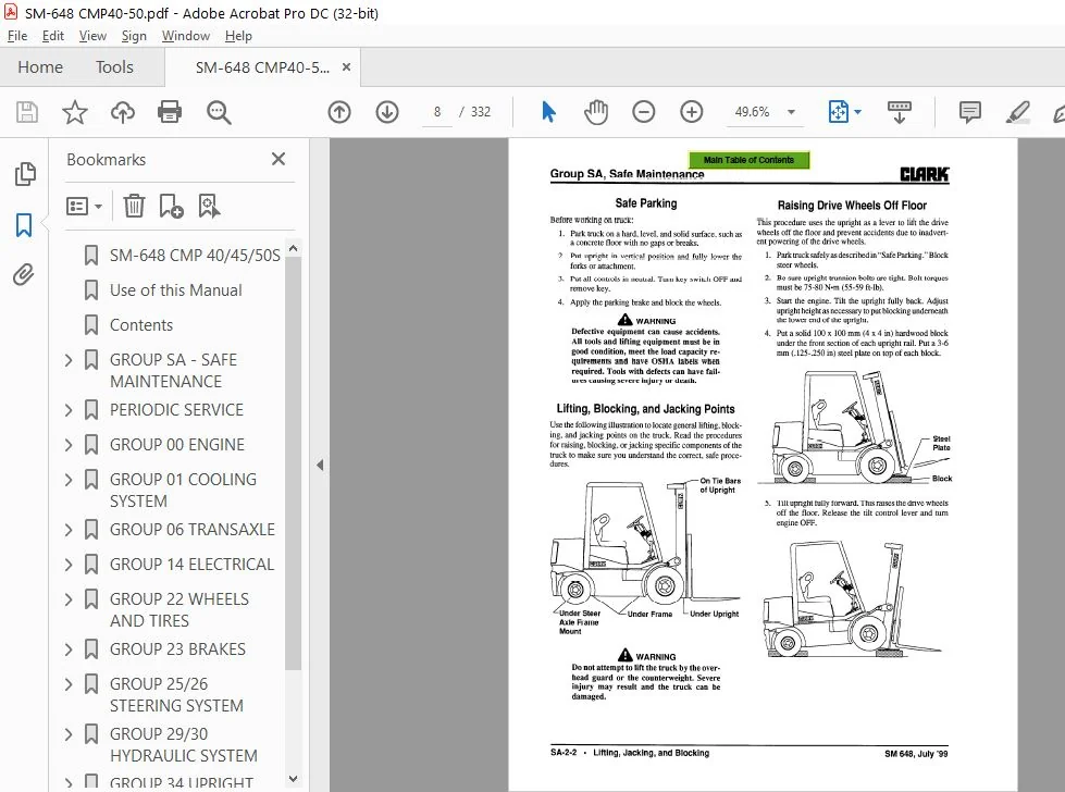
- c. Apply the parking brake. d. Stop the engine by turning off the ignition circuit. e. Put blocks at the wheels if truck is on an incline. Brakes, steering mechanisms, control mechanisms, warning devices, lights, governors, guards, safety devices, and frame members must be carefully and regularly inspected and maintained in a safe operating condition. Care must be taken to assure that all replacement parts, including tires, are interchangeable with the original parts and of a quality at least equal to that provided in the original equipment.
- Parts, including tires, are to be installed per the manufacturer’s procedures. Always use genuine CLARK or CLARK-approved parts. Use special care when removing heavy components from the truck, such as counterweight, seat deck, upright, etc. Be sure that lifting and handling equipment is of the correct capacity and in good condition. Also, this removal may upset the stability of the truck.
- The frame must always be safely blocked for major component removal. NOTE Special trucks or devices designed and approved for hazardous area operation must receive special attention to ensure that maintenance preserves the original, approved, safe-operating features. You should also he familiar with additional operating and maintenance safety instructions contained in the following publications: Fuel systems must be checked for leaks and condition of parts.
- Extra special consideration must be given in the case of a leak in the fuel system. Action must be taken to prevent the use of the truck until the leak has been corrected. ANSI/ASME B56.1- 1988 Operator Control-Industrial Tow Tractors (Safety Standard For Powered Industrial Trucks). Published by: Society of Mechanical Engineers, United Engineering Center, 345 E. 47th Street, New York, NY 10017.
- The truck manufacturer’s capacity, operation, and maintenance instruction plates, tags, or decals must be maintained in legible condition. NFPA 505-1982: Fire Safety Standard for Powered Industrial Trucks: Type Designations, Areas of Use, Maintenance and Operation. Available from: National Fire Protection Assoc., Inc., Batterymarch Park, Quincy, MA 02269. Batteries, motors, controllers, limit switches, protec- General Industrial Standards, OSHA 2206: OSHA Safety tive devices, electrical conductors, and connections and Health Standards (29 CFB 1910), Subpart N-Materials must be inspected and maintained in conformance Handling and Storage, Section 1910.178 Powered Induswith good practice. Special attention must be paid to trial Trucks.
- For sale by: Superintendent of Documents, the condition of electrical insulation. U.S. Government Printing Office, Washington, DC 20402.
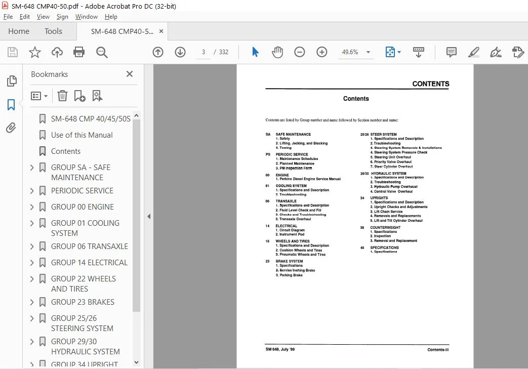
Table Of Contents:
CLARK FORKLIFT SM 648 CMP 404550S SERVICE MANUAL – PDF DOWNLOAD
SM-648 CMP 40/45/50S.............................................................................  1
Use of this Manual...............................................................................  2
Contents.........................................................................................  3
GROUP SA - SAFE MAINTENANCE......................................................................  4
	Section 1. Safety............................................................................  5
	Section 2. Lifting, Jacking, and Blocking....................................................  7
	Section 3. Towing............................................................................ 13
PERIODIC SERVICE................................................................................. 15
	Section 1. Maintenance Schedules............................................................. 16
		Service Chart/Lubrication Points......................................................... 17
		Recommended Periodic Service Schedule.................................................... 18
	Section 2. The Planned Maintenance Program................................................... 20
		Introduction to Planned Maintenance...................................................... 21
		The Basic PM Procedures.................................................................. 21
			Visual Inspection.................................................................... 22
			Functional Tests..................................................................... 23
			Air Cleaning the Truck............................................................... 25
			Truck Chassis Inspection and Lubrication............................................. 26
			Upright and Tilt Cylinder Lubrication................................................ 26
			Under-the-Hood Inspection............................................................ 26
			Fluid Checks......................................................................... 26
			Stall Test........................................................................... 27
			Cranking Voltage Test................................................................ 27
			Critical Fastener Torque Checks...................................................... 27
	Section 3. The PM Form....................................................................... 28
		PLANNED MAINTENANCE REPORT............................................................... 29
GROUP 00 ENGINE.................................................................................. 30
	Lubrication Diagrams......................................................................... 31
	Perkins - WORKSHOP MANUAL.................................................................... 33
		Contents................................................................................. 34
		General information...................................................................... 35
			Introduction......................................................................... 36
			Engine identification................................................................ 36
			Safety precautions................................................................... 38
			Asbestos joints...................................................................... 39
		Specifications........................................................................... 40
			Basic engine data.................................................................... 41
			Recommended torque tensions.......................................................... 42
			Data and dimensions.................................................................. 45
				Cylinder head assembly........................................................... 46
				Pistons and connecting rods...................................................... 49
				Crankshaft assembly.............................................................. 52
				Timing case and drive assembly................................................... 55
				Cylinder block assembly.......................................................... 56
				Aspiration system................................................................ 57
				Lubrication system............................................................... 57
				Fuel system...................................................................... 59
				Cooling system................................................................... 62
				Flywheel and housing............................................................. 63
				Electrical equipment............................................................. 63
				Auxiliary equipment.............................................................. 64
		Cylinder head assembly................................................................... 65
			General description.................................................................. 66
			Rocker cover......................................................................... 67
			Rocker assembly...................................................................... 68
			Valve tip clearances................................................................. 69
			Valve springs........................................................................ 70
			Cylinder head assembly............................................................... 71
			Valves and valve springs............................................................. 74
			Valve guides......................................................................... 76
			Cylinder head........................................................................ 77
		Piston and connecting rod assemblies..................................................... 79
			General description.................................................................. 80
			Big end bearing...................................................................... 81
			Piston and connecting rod assembly................................................... 82
			Piston rings......................................................................... 84
			Piston and connecting rod assembly................................................... 85
			Piston and rings..................................................................... 86
			Connecting rod....................................................................... 86
			Small end bush....................................................................... 87
			Piston cooling jets.................................................................. 87
		Crankshaft assembly...................................................................... 88
			General description.................................................................. 89
			Crankshaft pulley.................................................................... 90
			Rear oil seal assembly - engines which have the standard seal........................ 91
			Rear oil seal assembly - engines which have a flywheel housing that is oil filled.... 91
			Thrust washers....................................................................... 94
			Main bearing......................................................................... 95
			Crankshaft........................................................................... 96
			Balancer unit........................................................................ 98
		Timing case and drive assembly...........................................................103
			General description..................................................................104
			Timing case cover....................................................................105
			Front oil seal.......................................................................106
			Idler gear and hub...................................................................107
			Fuel pump gear.......................................................................108
			Camshaft gear........................................................................109
			Crankshaft gear......................................................................110
			Timing case..........................................................................111
			Camshaft and tappets.................................................................112
		Cylinder block assembly..................................................................114
			General description..................................................................115
			Cylinder block.......................................................................116
			Cylinder liner.......................................................................117
		Engines fitted with CAV fuel injection pumps.............................................120
			General descriptio’n.................................................................121
			To set number 1 piston to TDC on the compression stroke..............................122
			To check the valve timing............................................................123
			To check the timing of the fuel iniection DumD.......................................123
			To check the timing mark of the fuel injection pump..................................124
			To check the engine timing mark......................................................125
		Lubrication system.......................................................................126
			General description..................................................................127
			Filter canister......................................................................128
			Filter head..........................................................................128
			Sump.................................................................................129
			Oil strainer and suction pipe........................................................129
			Lubricating oil pump.................................................................130
			Relief Valve.........................................................................133
			Closed breather system...............................................................134
		Engines fitted with rotary fuel injection pumps..........................................135
			General description..................................................................136
			Fuel filter element..................................................................137
			Antomisers...........................................................................138
			Fuel lift pump.......................................................................139
			Fuel injection pump..................................................................141
		Cooling system...........................................................................149
			General description..................................................................150
			Thermostats..........................................................................151
			Water pump...........................................................................152
			Fan drive............................................................................155
			Lubricating oil cooler...............................................................156
			Cooler by-pass valve.................................................................159
		Flywheel and flywheel housing............................................................160
			General description..................................................................161
			Flywheel.............................................................................162
			Ring gear............................................................................162
			Flywheel housing.....................................................................163
		Electrical equipment.....................................................................164
			Alternators..........................................................................165
				General description..............................................................166
				Precautions......................................................................166
				Drive belts......................................................................167
				Alternator.......................................................................168
				Fault diagnosis..................................................................169
			Starter motors.......................................................................170
				General description..............................................................171
				Starter motor....................................................................172
			Starting aid.........................................................................173
				General description..............................................................174
				Starting aid.....................................................................174
		Power steering pump......................................................................175
			Power steering pump..................................................................176
			Adaptor for hydraulic pump/steering pump with splined drive..........................176
		List of special tools....................................................................177
GROUP 01 COOLING SYSTEM..........................................................................183
	Section 1. Cooling System Specifications and Description.....................................184
	Section 2. Cooling System Troubleshooting....................................................186
GROUP 06 TRANSAXLE...............................................................................187
	Section 1. Transaxle Specifications and Description..........................................188
	Section 2. Transaxle Fluids and Filters......................................................190
		Transmission Oil.........................................................................191
		Drive Axle Oil...........................................................................191
		Transmission Oil Filters.................................................................192
	Section 3. Transmission Checks and Troubleshooting...........................................193
		Troubleshooting..........................................................................194
		Pressure Check Ports.....................................................................196
	Section 4. Transaxle Overhaul................................................................198
		Overhaul Specifications..................................................................199
			Transmission Gear Box Shaft Unit.....................................................199
			Hub Reduction Unit...................................................................201
			Differential Gear Reduction Unit.....................................................203
			Charging Pump Driving Unit...........................................................205
			Cleaning and Inspection..............................................................206
		DRIVE AXLE OVERHAUL......................................................................207
			Separating the Transmission and Drive Axle...........................................207
			Disassembly of Hub...................................................................209
			Assembly of Hub......................................................................209
			Disassembly of Differential Carrier..................................................211
			Joining the Differential Carrier and Axle Housing....................................213
		TRANSMISSION Overhaul....................................................................214
			Torque Converter.....................................................................215
			Disassembly of the Transmission......................................................216
			Assembly of Transmission.............................................................223
			Assembly of the Control Valve........................................................227
			Mounting the Transmission to the Axle................................................229
			Replacing of Transmission Oil Filter.................................................230
			Servicing Machine after Transmission Overhaul........................................231
GROUP 14 ELECTRICAL..............................................................................232
	Section 1. Electrical System Specifications and Circuit Diagram..............................233
	Section 2. Instrument Pod....................................................................236
		Removal and Replacement..................................................................237
GROUP 22 WHEELS AND TIRES........................................................................238
	Section I. Wheels and Specifications and Tires Description...................................239
	Section 2. Pneumatic Wheels and Tires........................................................240
		Pneumatic Tire Maintenance Precaution....................................................241
		General Tire Maintenance, Inspection, and Repair.........................................242
			Inspection and Minor Repair..........................................................242
		Wheel Dismounting and Remounting.........................................................243
		Dual-Drive Wheel Remounting..............................................................244
		Wheel Disassembly and Tire Removal.......................................................245
		Tire Replacement and Wheel Reassembly....................................................247
			Tire-to-Wheel Mounting...............................................................248
			Filling Tires with Air...............................................................249
			Filling Tires with Nitrogen..........................................................249
			Checking and Adjusting Tire Pressure.................................................250
GROUP 23 BRAKES..................................................................................251
	Section 1. Brakes Specifications and Description.............................................252
	Section 2. Service and Inching Brakes........................................................256
		Pedals Adjustment........................................................................257
		Brake Bleeding...........................................................................257
		Removal/Installation of Brake Master Cylinder and Pedal Linkage..........................258
		Brake Valve/Master Cylinder Overhaul.....................................................259
	Section 3. Parking Brake.....................................................................261
GROUP 25/26 STEERING SYSTEM......................................................................262
	Section 1. Steering System Specifications and Description....................................263
		Specifications...........................................................................263
		Description..............................................................................264
		Schematic................................................................................264
		Construction.............................................................................265
		Operation................................................................................266
	Section 2. Steering System Troubleshooting...................................................267
	Section 3. Steering System Removals and Replacements.........................................269
	Section 4. Steering System Pressure Check and Adjustment.....................................272
	Section 5. Steering Unit Overhaul............................................................273
		Disassembly / Assembly...................................................................274
	Section 6. Priority Valve Overhaul...........................................................277
	Section 7. Steer Cylinder Overhaul...........................................................278
GROUP 29/30 HYDRAULIC SYSTEM.....................................................................279
	Section 1. Hydraulic System Specifications & Schematic Diagram ..............................280
	Section 2. Hydraulic System Troubleshooting..................................................284
		Pressure Check and Adjustment............................................................284
		Control Valve Troubleshooting............................................................285
		Pump Troubleshooting.....................................................................286
	Section 3. Hydraulic Pump Overhaul...........................................................288
		Main and Auxiliary Pumps Removal and Replacement.........................................289
		Main Hydraulic Pump Overhaul.............................................................290
			Disassembly..........................................................................290
			Assembly.............................................................................291
			Inspection and Assessment............................................................291
		Auxiliary Pump Overhaul..................................................................292
			Disassembly..........................................................................292
			Assembly.............................................................................292
			Inspection and Assessment............................................................293
		Start-Up.................................................................................294
	Section 4. Hydraulic Valve Overhaul..........................................................295
		Removal and Replacement..................................................................296
		Description..............................................................................298
		Disassembly..............................................................................299
		Assembly.................................................................................299
		Inspection and Assessment................................................................299
GROUP 34 UPRIGHT.................................................................................300
	Section 1. Upright  Specifications and Description...........................................301
	Section 2. Upright Checks and Adjustments....................................................303
		Performing Visual Inspection.............................................................304
			Mast.................................................................................304
			Carriage.............................................................................304
			Chains...............................................................................304
			Lift and Tilt Cylinders..............................................................304
			Forks................................................................................304
		Checking Trunnion Mounts.................................................................305
		Checking and Adjusting Carriage Side Roller..............................................305
		Checking Carriage and Mast Shim..........................................................306
		Adjusting Standard Mast Shim.............................................................307
		Adjusting Full Free Lift Two-Stage Mast Shim.............................................308
		Adjusting Full Free Lift Three-Stage Mast Shim...........................................309
		Checking and Adjusting Cylinder Racking..................................................310
	Section 3. Lift Chain Service................................................................311
	Section 4. Removals and Replacements.........................................................313
		Removing and Installing Mast.............................................................314
		Carriage Removal and Replacement.........................................................315
		Forks....................................................................................316
	Section 5. Lift and Tilt Cylinder Overhaul...................................................317
GROUP 38 COUNTERWEIGHT...........................................................................320
	Section 1. Specifications....................................................................320
	Section 2. Inspection........................................................................320
	Section 3. Removal and Replacement...........................................................321
GROUP 40 SPECIFICATIONS..........................................................................322
	Section 1. Specifications....................................................................323
		Dimensions and Weight Specifications.....................................................324
		Performance Specifications...............................................................325
		Service Specifications by Group..........................................................326
		Fluids Specifications....................................................................328
		Critical Torque Specifications...........................................................329
		Standard Tightening Torque...............................................................330
		Metric Conversion Chart..................................................................331
		Hydraulic Fitting Tightening Procedure...................................................332
Please Note:
- This is the SAME exact manual used by your dealers to fix your vehicle.
- The same can be yours in the next 2-3 mins as you will be directed to the download page immediately after paying for the manual.
- Any queries / doubts regarding your purchase, please feel free to contact [email protected]