Trusted Business
Verified & Licensed
Virus Free Files
100% Safe Downloads
Secure Payment
SSL Protected
Instant Delivery
Available Immediately
Sale!


CLARK FORKLIFT SM.649 CMP50607 SERVICE MANUAL
Original price was: $76.95.$26.95Current price is: $26.95.
CLARK FORKLIFT SM 649 CMP50607 SERVICE MANUAL – PDF DOWNLOAD
Instant PDF Download
Available immediately
Save to Your Device
Download & keep forever
Antivirus Scanned
100% virus-free
Trusted Worldwide
175,000+ customers
Description
CLARK FORKLIFT SM 649 CMP50607 SERVICE MANUAL – PDF DOWNLOAD
Questions? Email us: [email protected]
Image Preview:
Description:
CLARK FORKLIFT SM 649 CMP50607 SERVICE MANUAL – PDF DOWNLOAD
- The following instructions have been prepared from current industry and government safety standards applicable to industrial truck operation and maintenance. These recommended procedures specify conditions, methods, and accepted practices that aid in the safe maintenance of industrial trucks. They are listed here for the reference and safety of all workers during maintenance operations.
- Carefully read and understand these instructions and the specific maintenance procedures before attempting to do any repair work. When in doubt of any maintenance procedure, please contact your local Clark dealer. 1. IMPORTANT Powered industrial trucks can become hazardous if maintenance is neglected. Therefore, suitable maintenance facilities, trained personnel, and procedures must be provided. This message is used when special precautions should be taken to ensure a correct action or to avoid damage to, or malfunction of, the truck or a component.
- 2. Maintenance and inspection of all powered industrial trucks shall be done in conformance with the manufacturer’s recommendations. 3. A CAUTION This message is used as a reminder of safety hazards that can result in personal injury if proper precautions are not taken. A scheduled planned maintenance, lubrication, and inspection program shall be followed. 4. Only trained and authorized personnel shall be permitted to maintain, repair, adjust, and inspect industrial trucks. Work should be performed in accordance with the manufacturer’s specifications.
- A WARNING This message is used when a hazard exists that can result in injury or death if proper precautions are not taken. 5. Properly ventilate work area, vent exhaust fumes, and keep shop clean and floor dry. 6. A DANGER This message is used when an extreme hazard exists that can result in injury or death or serious injury if proper precautions are not taken. Avoid fire hazards and have fire protection equipment present in the work area. Do not use an open flame to check for level or leakage of fuel, electrolyte, or coolant.
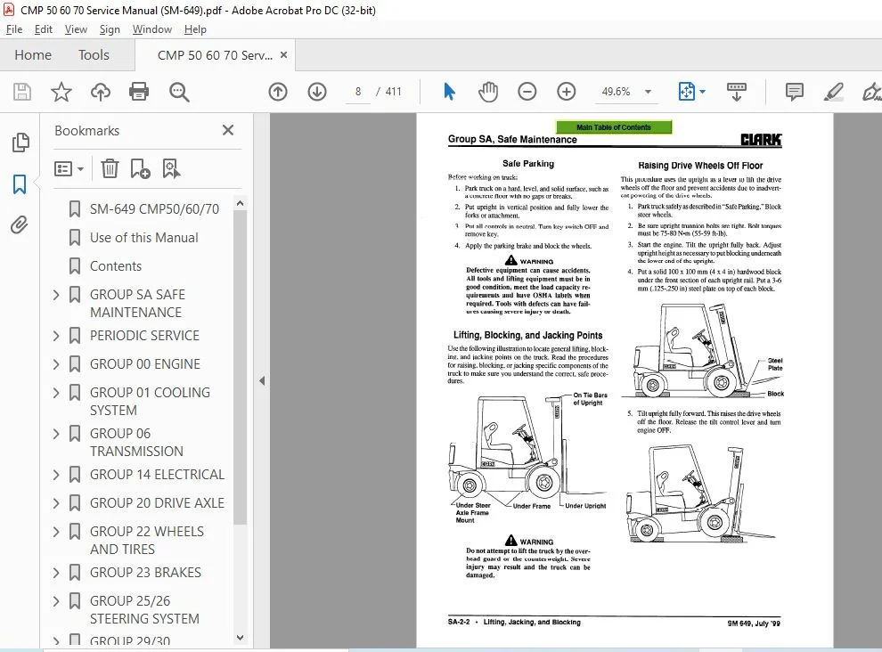
- Do not use open pans of fuel or flammable cleaning fluids for cleaning parts. 7. Before starting work on truck: The above terms have been adopted by Clark Material Handling Company. The same terms may be used in different context in service literature supplied directly or indirectly by vendors of truck components. a. Raise drive wheels off of floor or disconnect power source and use blocks or other positive truck positioning devices.
- b. Disconnect battery before working on the electrical system. 8. Before working on engine fuel system of gasoline- or diesel-powered trucks, be sure the fuel shut-off valve is closed.
Table Of Contents:
CLARK FORKLIFT SM 649 CMP50607 SERVICE MANUAL – PDF DOWNLOAD
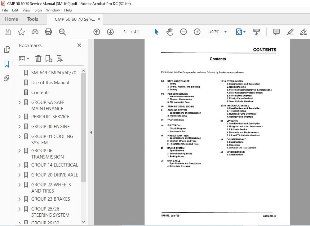
SM-649 CMP50/60/70...............................................................................  1
Use of this Manual...............................................................................  2
Contents.........................................................................................  3
GROUP SA SAFE MAINTENANCE........................................................................  4
	Section 1. Safety............................................................................  5
	Section 2. Lifting, Jacking, and Blocking....................................................  7
		Safe Parking.............................................................................  8
		Lifting, Blocking, and Jacking Points....................................................  8
		Raising Drive Wheels Off Floor...........................................................  8
		Raising Truck with a Hoist...............................................................  9
		Blocking the Upright In Raised Position.................................................. 10
		Raising Rear of Truck.................................................................... 10
		Raising Entire Truck..................................................................... 11
		Shipping Tie-Down Instructions........................................................... 12
	Section 3. Towing............................................................................ 13
PERIODIC SERVICE................................................................................. 15
	Section 1. Maintenance Schedules............................................................. 16
		Service Chart/Lubrication Points......................................................... 17
		Recommended Periodic Service Schedule.................................................... 18
	Section 2. The Planned Maintenance Program................................................... 20
		Introduction to Planned Maintenance...................................................... 21
		The Basic PM Procedures.................................................................. 21
		Visual Inspection........................................................................ 22
		Functional Tests......................................................................... 23
		Air Cleaning the Truck................................................................... 25
		Truck Chassis Inspection and Lubrication................................................. 26
		Upright and Tilt Cylinder Lubrication.................................................... 26
		Lift Chain Lubrication................................................................... 26
		Under-the-Hood Inspection................................................................ 26
		Fluid Checks............................................................................. 26
		Stall Test............................................................................... 27
		Cranking Voltage Test.................................................................... 27
		Critical Fastener Torque Checks.......................................................... 27
	Section 3. The PM Form....................................................................... 28
GROUP 00 ENGINE.................................................................................. 30
	Lubrication Diagrams......................................................................... 31
	Perkins WORKSHOP MANUAL...................................................................... 33
		Contents................................................................................. 34
		General information...................................................................... 35
			Introduction......................................................................... 36
			Engine identification................................................................ 36
			Safety precautions................................................................... 38
			Asbestos joints...................................................................... 39
		Specifications........................................................................... 40
			Basic engine data.................................................................... 41
			Recommended torque tensions.......................................................... 42
			Data and dimensions.................................................................. 45
				Introduction..................................................................... 46
				Cylinder head assembly........................................................... 46
				Pistons and connecting rods...................................................... 49
				Crankshaft assembly.............................................................. 52
				Timing case and drive assembly................................................... 55
				Cylinder block assembly.......................................................... 56
				Aspiration system................................................................ 57
				Lubrication system............................................................... 57
				Fuel system...................................................................... 59
				Cooling system................................................................... 62
				Flywheel and housing............................................................. 63
				Electrical equipment............................................................. 63
				Auxiliary equipment.............................................................. 64
		Cylinder head assembly................................................................... 65
			General description.................................................................. 66
			Rocker cover......................................................................... 67
			Rocker assembly...................................................................... 68
			Valve tip clearances................................................................. 69
			Valve springs........................................................................ 70
			Cylinder head assembly............................................................... 71
			Valves and valve springs............................................................. 74
			Valve guides......................................................................... 76
			Cylinder head........................................................................ 77
		Piston and connecting rod assemblies..................................................... 79
			General description.................................................................. 80
			Big end bearing...................................................................... 81
			Piston and connecting rod assembly................................................... 82
			Piston rings......................................................................... 84
			Piston and connecting rod assembly................................................... 85
			Piston and rings..................................................................... 86
			Connecting rod....................................................................... 86
			Small end bush....................................................................... 87
			Piston cooling jets.................................................................. 87
		Crankshaft assembly...................................................................... 88
			General description.................................................................. 89
			Crankshaft pulley.................................................................... 90
			Rear oil seal assembly - engines which have the standard seal........................ 91
			Rear oil seal assembly - engines which have a flywheel housing that is oil filled.... 91
			Thrust washers....................................................................... 94
			Main bearing......................................................................... 95
			Crankshaft........................................................................... 96
			Balancer unit........................................................................ 98
				To remove and to fit............................................................. 98
				To dismantle..................................................................... 99
				To assemble......................................................................100
				To inspect.......................................................................101
				To remove and to fit the needle roller bearings for the drive shaft..............102
				To remove and to fit the bushes for the balance weights..........................102
		Timing case and drive assembly...........................................................103
			General description..................................................................104
			Timing case cover....................................................................105
			Front oil seal.......................................................................106
			Idler gear and hub...................................................................107
			Fuel pump gear.......................................................................108
			Camshaft gear........................................................................109
			Crankshaft gear......................................................................110
			Timing case..........................................................................111
			Camshaft and tappets.................................................................112
		Cylinder block assembly..................................................................114
			General description..................................................................115
			Cylinder block.......................................................................116
			Cylinder liner.......................................................................117
		Engines fitted with CAV fuel injection pumps.............................................120
			General description..................................................................121
			To set number 1 piston to TDC on the compression stroke..............................122
			An alternative method to set number 1 piston to TDC on the compression stroke........122
			To check the valve timing............................................................123
			To check the timing of the fuel iniection pump.......................................123
			To check the timing mark of the fuel injection pump..................................124
			To check the engine timing mark......................................................125
		Lubrication system.......................................................................126
			General description..................................................................127
			Filter canister......................................................................128
			Filter head..........................................................................128
			Sump.................................................................................129
			Oil strainer and suction pipe........................................................129
			Lubricating oil pump.................................................................130
				To remove and to fit.............................................................130
				To renew the shaft for the idler gear............................................131
				To inspect.......................................................................132
			Relief valve.........................................................................133
			Closed breather system...............................................................134
		Engines fitted with a rotary fuel injection pump.........................................135
			General description..................................................................136
			Fuel filter element..................................................................137
			Atomisers............................................................................138
			Fuel lift pump.......................................................................139
			Fuel injection pump..................................................................141
				To remove and to fit - Bosch pump................................................141
				To remove and to fit - CAV pump..................................................144
				To adjust - Bosch pump...........................................................145
				To adjust - CAV pump.............................................................145
				To eliminate air from the fuel system - Bosch pump...............................146
				To eliminate air from the fuel system - CAV pump.................................147
		Cooling system...........................................................................149
			General description..................................................................150
			Thermostats..........................................................................151
			Water pump...........................................................................152
			Fan..................................................................................155
			Fan drive............................................................................155
			Lubricating oil cooler...............................................................156
			Cooler by-pass valve.................................................................159
		Flywheel and flywheel housing............................................................160
			General description..................................................................161
			Flywheel.............................................................................162
			Ring gear............................................................................162
			Flywheel housing.....................................................................163
		Electrical equipment.....................................................................164
			Alternators..........................................................................165
				General description..............................................................166
				Precautions......................................................................166
				Drive belts......................................................................167
				Alternator.......................................................................168
				Fault diagnosis..................................................................169
			Starter motors.......................................................................170
				General description..............................................................171
				Starter motor....................................................................172
			Starting aid.........................................................................173
				General description..............................................................174
				Starting aid.....................................................................174
		Power steering pump......................................................................175
			Power steering pump..................................................................176
			Adaptor for hydraulic pump/steering pump with splined drive..........................176
		List of special tools....................................................................177
GROUP 01 COOLING SYSTEM..........................................................................183
	Section 1. Cooling System Specifications and Description.....................................184
	Section 2. Cooling System Troubleshooting....................................................186
GROUP 06 TRANSMISSION............................................................................187
	DISASSEMBLY / REASSEMBLY.....................................................................188
		DISASSEMBLY AND REASSEMBLY OF(IST) AND 2ND CLUTCH........................................200
			DISASSEMBLY..........................................................................200
				IST CLUTCH DISASSEMBLY...........................................................200
				2nd CLUTCH ASSEMBLY..............................................................204
				1ST CLUTCH REASSEMBLY............................................................208
				2ND CLUTCH REASSEMBLY............................................................214
		DISASSEMBLY AND REASSEMBLY OF 3RD CLUTCH.................................................220
			DISASSEMBLY..........................................................................220
			3RD CLUTCH REASSEMBLY................................................................223
		DISASSEMBLY AND REASSEMBLY OF FORWARD AND REVERSE CLUTCHES...............................227
			REVERSE CLUTCH DISASSEMBLY...........................................................227
			FORWARD CLUTCH DISASSEMBLY...........................................................230
			FORWARD CLUTCH REASSEMBLY............................................................233
			REVERSE CLUTCH REASSEMBLY............................................................238
		REGULATOR VALVE DISASSEMBLY AND REASSEMBLY...............................................244
		DISASSEMBLY AND REASSEMBLY OF SPACER PLATE...............................................245
			DISASSEMBLY..........................................................................245
			SPACER PLATE REASSEMBLY..............................................................250
		DISASSEMBLY AND REASSEMBLY OF CONVERTER HOUSING..........................................255
			DISASSEMBLY..........................................................................255
			CONVERTER HOUSING REASSEMBLY.........................................................258
		OUTPUT FLANGE OIL SEAL SLEEVE DISASSEMBLY AND REASSEMBLY.................................261
		OUTPUT FLANGE AND PARKING BRAKE DISC @...................................................262
	REASSEMBLY OF TRANSMISSION...................................................................264
		ELECTRIC CONTROL VALVE ASSEMBLY..........................................................271
		DRIVE PLATE INSTALLATION.................................................................276
		TRANSMISSION TO ENGINE INSTALLATION PROCEDURE............................................277
		SPECIFICATIONS AND SERVICE DATA-POWER SHIFT TRANSMISSION AND TORQUE CONVERTER............278
		LUBRICATION..............................................................................279
	SERVICING MACHINE AFTER TRANSMISSION OVERHAUL................................................280
	EXTERNAL PLUMBING AND PRESSURE CHECK POINTS..................................................281
	CLEANING AND INSPECTION......................................................................283
	PARKING BRAKE LINING AND PISTON REPLACEMENT PROCEDURE........................................285
	TROUBLESHOOTING GUIDE FOR THE TRANSMISSION...................................................286
		Stall Test...............................................................................287
		Transmission Pressure Checks.............................................................287
		Mechanical Checks........................................................................287
		Hydraulic Check..........................................................................288
		CONVERTER STALL PROCEDURE................................................................288
		TROUBLESHOOTING GUIDE....................................................................289
	3 SPEED ASSEMBLY INSTRUCTION.................................................................290
	ASSEMBLY NOTES...............................................................................292
	TORQUE SPECIFICATION FOR LUBRICATED OR PLATED SCREWS AND NUTS................................294
GROUP 14 ELECTRICAL..............................................................................295
	Section 1. Electrical System Specifications and Circuit Diagram..............................296
	Section 2. Instrument Pod....................................................................299
GROUP 20 DRIVE AXLE..............................................................................301
	Section 1. Drive Axle Specifications and Description.........................................302
	Section 2. Drive Axle Overhaul...............................................................304
		Overhaul Specifications..................................................................305
		Drive Axle Disassembly...................................................................305
		Differential Disassembly.................................................................307
		Drive Axle Cleaning......................................................................307
		Drive Axle Inspection....................................................................307
		Differential Reassembly..................................................................309
		Drive Axe Reassembly.....................................................................311
GROUP 22 WHEELS AND TIRES........................................................................314
	Section 1. Wheels and Tires Specifications and Description...................................315
	Section 2. Pneumatic Wheels and Tires........................................................316
		Pneumatic Tire Maintenance Precaution....................................................317
		General Tire Maintenance, Inspection, and Repair.........................................318
		Wheel Dismounting and Remounting.........................................................319
		Drive and Steer Wheel Dismounting........................................................319
		Drive and Steer Wheel Remounting.........................................................319
		Dual-Drive Wheel Dismounting.............................................................320
		Dual-Drive Wheel Remounting..............................................................320
		Wheel Disassembly and Tire Removal.......................................................321
		Tire Replacement and Wheel Reassembly....................................................323
		Tire-to-Wheel Mounting...................................................................324
		Filling Tires with Air...................................................................325
		Filling Tires with Nitrogen..............................................................325
		Checking and Adjusting Tire Pressure.....................................................326
GROUP 23 BRAKES..................................................................................327
	Section 1. Brakes Specifications and Description.............................................328
	Section 2. Service and Inching Brakes........................................................332
		Pedals Adjustment........................................................................333
		Brake Bleeding...........................................................................333
		Removal/Installation of Master Cylinders and Pedal Arramgement...........................335
		Brake Valve Overhaul.....................................................................336
		Brake Shoe and Lining Replacement........................................................337
		Wheel Cylinder Inspection................................................................337
		Brake Drum Inspection....................................................................338
		Automatic Adjuster.......................................................................338
		Special Brake Tools......................................................................339
	Section 3. Parking Brake.....................................................................340
		Parking Brake Adjustment.................................................................341
		Lever and Cable Installation.............................................................341
		Parking Brake Lining and Piston Replacement..............................................342
		Parking Brake Adjustment.................................................................343
GROUP 25/26 STEERING SYSTEM......................................................................344
	Section 1. Steering System Specifications and Description....................................345
		Specifications...........................................................................345
		Description..............................................................................346
		Schematic................................................................................346
		Construction.............................................................................347
			Rotary Valve Bank....................................................................348
			Gerotor Set..........................................................................348
		Operation................................................................................348
	Section 2. Steering System Troubleshooting...................................................349
	Section 3. Steering System Removals and Replacements.........................................351
	Section 4. Steering System Pressure Check and Adjustment.....................................354
	Section 5. Steering Unit Overhaul............................................................355
	Section 6. Priority Valve Overhaul...........................................................359
	Section 7. Steer Cylinder Overhaul...........................................................360
GROUP 29/30 HYDRAULIC SYSTEM.....................................................................361
	Section 1. Hydraulic System Specifications & Schematic Diagram...............................362
	Section 2. Hydraulic System Troubleshooting..................................................366
		Pressure Check and Adjustment............................................................366
		Control Valve Troubleshooting............................................................367
	Section 3. Hydraulic Pump Overhaul...........................................................369
		Main and Auxiliary Pumps Removal and Replacement.........................................370
		Main and Auxiliary Pump Overhaul.........................................................371
	Section 4. Hydraulic Valve Overhaul..........................................................374
		Removal and Replacement..................................................................375
		Description..............................................................................377
		Disassembly..............................................................................378
		Assembly.................................................................................378
		Inspection and Assessment................................................................378
GROUP 34 UPRIGHT.................................................................................379
	Section 1. Upright Specifications and Description............................................380
	Section 2. Upright Checks and Adjustments....................................................382
		Performing Visual Inspection.............................................................383
		Checking and Adjusting Carriage Side Roller..............................................384
		Checking Carriage and Mast Shim..........................................................385
		Adjusting Standard Mast Shim.............................................................386
		Adjusting Full Free Lift Two-Stage Mast Shim.............................................387
		Adjusting Full Free Lift Three-Stage Mast Shim...........................................388
		Checking and Adjusting Cylinder Racking..................................................389
	Section 3. Lift Chain Service................................................................390
	Section 4. Removals and Replacements.........................................................392
		Removing and Installing Mast.............................................................393
		Carriage Removal and Replacement.........................................................394
		Forks....................................................................................395
	Section 5. Lift and Tilt Cylinder Overhaul...................................................396
GROUP 38 COUNTERWEIGHT...........................................................................399
	Section 1. Specifications....................................................................399
	Section 2. Inspection........................................................................399
	Section 3. Removal and Replacement...........................................................400
GROUP 40 SPECIFICATIONS..........................................................................401
	Section 1. Specifications....................................................................402
		Dimensions and Weight Specifications.....................................................403
		Performance Specifications...............................................................404
		Service Specifications by Group..........................................................405
		Fluids Specifications....................................................................407
		Critical Torque Specifications...........................................................408
		Standard Tightening Torque...............................................................409
		Metric Conversion Chart..................................................................410
		Hydraulic Fitting Tightening Procedure...................................................411
Please Note:
- This is the SAME manual used by the dealers to troubleshoot any faults in your vehicle. This can be yours in 2 minutes after the payment is made.
- Contact us at [email protected] should you have any queries before your purchase or that you need any other service / repair / parts operators manual.