Class-Atles 926,236,946 Use&Maintenance Manual – PDF DOWNLOAD
Original price was: $78.00.$25.95Current price is: $25.95.
Class-Atles 926,236,946 Use&Maintenance Manual – PDF DOWNLOAD
Description
Class-Atles 926,236,946 Use&Maintenance Manual – PDF DOWNLOAD
DESCRIPTION:
Class-Atles 926,236,946 Use&Maintenance Manual – PDF DOWNLOAD
For your safety
Before using the tractor for the first time, read the user’s
manual and observe the general safety instructions!
WARNING TRIANGLE
In this user’s manual, this sign indicates all the
paragraphs concerning safety aspects. Pass on these safety
instructions to all other users.
The instruction and warning plates affixed to the tractor give
important information about possible risks of use. Respect for
these instructions is a guarantee of your safety!
Appropriate use
This tractor has been designed to be used exclusively for
normal agricultural work (appropriate use).
Any use other than that defined above will be considered as
inappropriate and will release the manufacturer from any
liability in the event of damage or injury; the user alone will
bear the risks resulting from such misuse.
Appropriate use also supposes the observance of the
operating, maintenance and repair regulations laid down by
the manufacturer.
The tractor must be used, maintained and repaired only by
persons with a thorough knowledge of the vehicle and aware
of the possible risks.
Specific accident prevention instructions must be observed
as well as general rules concerning technical safety, health
and safety regulations and the highway code.
The manufacturer declines all responsibility for any damage
resulting from any modification made to the tractor without
their approval.
TABLE OF CONTENTS:
Class-Atles 926,236,946 Use&Maintenance Manual – PDF DOWNLOAD
SOMMAIRE……………………………………………………………………………………………………………………………………………………………………………………………………………………… 1
For your safety……………………………………………………………………………………………………………………………………………………………………………………………………………. 1
Warning triangle…………………………………………………………………………………………………………………………………………………………………………………………………………… 1
Appropriate use……………………………………………………………………………………………………………………………………………………………………………………………………………. 1
Chapter symbols……………………………………………………………………………………………………………………………………………………………………………………………………………….. 3
Notes………………………………………………………………………………………………………………………………………………………………………………………………………………………… 4
SOMMAIRE………………………………………………………………………………………………………………………………………………………………………………………………………………….. 5
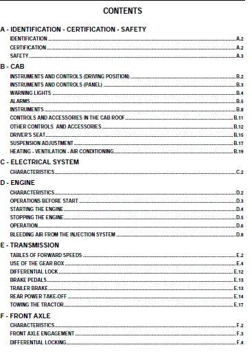
A – IDENTIFICATION – CERTIFICATION – SAFETY……………………………………………………………………………………………………………………………………………………………………………….. 5
IDENTIFICATION A.2………………………………………………………………………………………………………………………………………………………………………………………………….. 5
Certification A.2…………………………………………………………………………………………………………………………………………………………………………………………………… 5
SAFETY A.3…………………………………………………………………………………………………………………………………………………………………………………………………………. 5
B – CAB……………………………………………………………………………………………………………………………………………………………………………………………………………….. 5
INSTRUMENTS AND CONTROLS (driving position) B.2………………………………………………………………………………………………………………………………………………………………………… 5
INSTRUMENTS AND CONTROLS (panel) B.3………………………………………………………………………………………………………………………………………………………………………………….. 5
WARNING LIGHTS B.4………………………………………………………………………………………………………………………………………………………………………………………………….. 5
ALARMS B.5…………………………………………………………………………………………………………………………………………………………………………………………………………. 5
INSTRUMENTS B.8…………………………………………………………………………………………………………………………………………………………………………………………………….. 5
Controls and accessories in the cab roof B.11………………………………………………………………………………………………………………………………………………………………………….. 5
OTHER CONTROLS AND ACCESSORIES B.12…………………………………………………………………………………………………………………………………………………………………………………… 5
DRIVER’S SEAT B.15………………………………………………………………………………………………………………………………………………………………………………………………….. 5
SUSPENSION ADJUSTMENT B.17…………………………………………………………………………………………………………………………………………………………………………………………… 5
HEATING – VENTILATION – AIR CONDITIONING B.19………………………………………………………………………………………………………………………………………………………………………….. 5
C – ELECTRICAL SYSTEM…………………………………………………………………………………………………………………………………………………………………………………………………… 5
CHARACTERISTICS C.2…………………………………………………………………………………………………………………………………………………………………………………………………. 5
D – ENGINE…………………………………………………………………………………………………………………………………………………………………………………………………………….. 5
CHARACTERISTICS D.2…………………………………………………………………………………………………………………………………………………………………………………………………. 5
Operations before start D.3………………………………………………………………………………………………………………………………………………………………………………………….. 5
STARTING THE ENGINE D.4……………………………………………………………………………………………………………………………………………………………………………………………… 5
STOPPING THE ENGINE D.5……………………………………………………………………………………………………………………………………………………………………………………………… 5
OPERATION D.6………………………………………………………………………………………………………………………………………………………………………………………………………. 5
Bleeding air from the injection system D.8…………………………………………………………………………………………………………………………………………………………………………….. 5
E – TRANSMISSION……………………………………………………………………………………………………………………………………………………………………………………………………….. 5
Tables of forward speeds E.2…………………………………………………………………………………………………………………………………………………………………………………………. 5
Use of the gear box E.4……………………………………………………………………………………………………………………………………………………………………………………………… 5
Differential lock E.12………………………………………………………………………………………………………………………………………………………………………………………………. 5
Brake pedals E.13…………………………………………………………………………………………………………………………………………………………………………………………………… 5
Trailer brake E.13………………………………………………………………………………………………………………………………………………………………………………………………….. 5
Rear power take-off E.14…………………………………………………………………………………………………………………………………………………………………………………………….. 5
Towing the tractor E.17……………………………………………………………………………………………………………………………………………………………………………………………… 5
F – Front axle…………………………………………………………………………………………………………………………………………………………………………………………………………. 5
CHARACTERISTICS F.2…………………………………………………………………………………………………………………………………………………………………………………………………. 5
Front axle engagement F.3……………………………………………………………………………………………………………………………………………………………………………………………. 5
Differential locking F.4…………………………………………………………………………………………………………………………………………………………………………………………….. 5
G – Hydraulics – linkage and rear hitch…………………………………………………………………………………………………………………………………………………………………………………… 6
Characteristics G.2…………………………………………………………………………………………………………………………………………………………………………………………………. 6
REAR LINKAGE TCE 25 (Electronic tracto control) G.3…………………………………………………………………………………………………………………………………………………………………….. 6
Auxiliary spool valves G.10………………………………………………………………………………………………………………………………………………………………………………………….. 6
Electropilot G.12…………………………………………………………………………………………………………………………………………………………………………………………………… 6
REAR HITCH ADJUSTMENT INSTRUCTIONS G.15……………………………………………………………………………………………………………………………………………………………………………….. 6
AUTOMATIC HITCHES G.17………………………………………………………………………………………………………………………………………………………………………………………………. 6
H – FRONT POWER TAKEOFF, LINKAGE AND FRONT COUPLING………………………………………………………………………………………………………………………………………………………………………… 6
CHARACTERISTICS H.2…………………………………………………………………………………………………………………………………………………………………………………………………. 6
USING THE FRONT POWER TAKEOFF H.5…………………………………………………………………………………………………………………………………………………………………………………….. 6
I – On board computer…………………………………………………………………………………………………………………………………………………………………………………………………… 6
On-board computer (INFOTRAC) I.2……………………………………………………………………………………………………………………………………………………………………………………… 6
OPERATION I.4………………………………………………………………………………………………………………………………………………………………………………………………………. 6
INFOTRAC CALIBRATION PROCEDURE “Operating speed” I.8……………………………………………………………………………………………………………………………………………………………………. 6
J – WHEELS AND TYRES……………………………………………………………………………………………………………………………………………………………………………………………………. 6
GENERAL J.2………………………………………………………………………………………………………………………………………………………………………………………………………… 6
TYRE PRESSURES J.2………………………………………………………………………………………………………………………………………………………………………………………………….. 6
front and rear axle characteristics J.4……………………………………………………………………………………………………………………………………………………………………………….. 6
SETTING THE TRACK J.9……………………………………………………………………………………………………………………………………………………………………………………………….. 6
Adjusting the track with smooth shaft rear axle J.10……………………………………………………………………………………………………………………………………………………………………. 6
Front axle steering lock stops J.10…………………………………………………………………………………………………………………………………………………………………………………… 6
DUAL WHEELS J.11……………………………………………………………………………………………………………………………………………………………………………………………………. 6
USING DEEP-WORKING IMPLEMENTS J.12……………………………………………………………………………………………………………………………………………………………………………………. 6
K – Dimensions, weights, capacities and ballast……………………………………………………………………………………………………………………………………………………………………………. 6
Dimensions and weights K.2…………………………………………………………………………………………………………………………………………………………………………………………… 6
Capacities K.3……………………………………………………………………………………………………………………………………………………………………………………………………… 6
Ballasts K.4……………………………………………………………………………………………………………………………………………………………………………………………………….. 6
L – Maintenance………………………………………………………………………………………………………………………………………………………………………………………………………… 6
General L.2………………………………………………………………………………………………………………………………………………………………………………………………………… 6
M – Operations that are mandatory under the guarantee………………………………………………………………………………………………………………………………………………………………………. 6
OPERATIONS MANDATORY UNDER THE TERMS OF THE CONTRACTUAL GUARANTEE M.2…………………………………………………………………………………………………………………………………………………….. 6
A – IDENTIFICATION – CERTIFICATION – SAFETY……………………………………………………………………………………………………………………………………………………………………………….. 7
IDENTIFICATION……………………………………………………………………………………………………………………………………………………………………………………………………… 8
Certification………………………………………………………………………………………………………………………………………………………………………………………………………. 8
SAFETY…………………………………………………………………………………………………………………………………………………………………………………………………………….. 9
FOREWORD……………………………………………………………………………………………………………………………………………………………………………………………………….. 9
PRECAUTIONS BEFORE STARTING………………………………………………………………………………………………………………………………………………………………………………………. 9
CONDITION OF THE TRACTOR…………………………………………………………………………………………………………………………………………………………………………………………. 10
ADJUSTMENT OR MAINTENANCE – REPAIRS……………………………………………………………………………………………………………………………………………………………………………….. 11
AXLE STANDS…………………………………………………………………………………………………………………………………………………………………………………………………. 12
HYDRAULIC SYSTEMS……………………………………………………………………………………………………………………………………………………………………………………………. 12
ELECTRICAL SYSTEM……………………………………………………………………………………………………………………………………………………………………………………………. 13
FUEL……………………………………………………………………………………………………………………………………………………………………………………………………….. 13
Re-fuelling……………………………………………………………………………………………………………………………………………………………………………………………… 13
Coolant…………………………………………………………………………………………………………………………………………………………………………………………………….. 13
ROAD USE – USE FOR TRANSPORT……………………………………………………………………………………………………………………………………………………………………………………… 14
OPERATION………………………………………………………………………………………………………………………………………………………………………………………………………. 15
GENERAL RULE………………………………………………………………………………………………………………………………………………………………………………………………… 15
WHEEL TRACK…………………………………………………………………………………………………………………………………………………………………………………………………. 15
ATTACHING IMPLEMENTS…………………………………………………………………………………………………………………………………………………………………………………………. 15
DRIVING…………………………………………………………………………………………………………………………………………………………………………………………………….. 15
STATIONARY WORK……………………………………………………………………………………………………………………………………………………………………………………………… 16
USE OF TOOLS DRIVEN BY THE PTO………………………………………………………………………………………………………………………………………………………………………………… 16
TOXIC PRODUCTS………………………………………………………………………………………………………………………………………………………………………………………………….. 17
IMPORTANT…………………………………………………………………………………………………………………………………………………………………………………………………… 17
Air conditioning………………………………………………………………………………………………………………………………………………………………………………………………… 18
RECOMMENDATIONS:…………………………………………………………………………………………………………………………………………………………………………………………….. 18
IMPORTANT…………………………………………………………………………………………………………………………………………………………………………………………………… 18
SAFETY CABS…………………………………………………………………………………………………………………………………………………………………………………………………….. 18
Safety stickers with warning pictograms……………………………………………………………………………………………………………………………………………………………………………. 19
C – Safety:…………………………………………………………………………………………………………………………………………………………………………………………………. 19
D – Note:…………………………………………………………………………………………………………………………………………………………………………………………………… 19
E – Note:…………………………………………………………………………………………………………………………………………………………………………………………………… 19
F – Note:…………………………………………………………………………………………………………………………………………………………………………………………………… 19
G – Note: The power take-off must not be used at 1000 rpm unless the implement is designed to run at this speed (see the user’s manual)…………………………………………………………………………………… 20
H – Note: To prevent accidents. Disconnect the hydraulic hoses (of the grab hook) from the distributors immediately after locking on the implement…………………………………………………………………………. 20
I – Note: Keep the linkage clear when you are using the external controls………………………………………………………………………………………………………………………………………….. 20
J – Danger: Do not place the starter terminals in contact with a tool that conducts electricity (danger of sparks)……………………………………………………………………………………………………… 20
K – Do not discard a worn battery but take it to a recycling collection point………………………………………………………………………………………………………………………………………. 21
L – Danger: To prevent any damage to the eyes, never look at the surface of the radar sensor when it is activated………………………………………………………………………………………………………. 21
M – Never place a foot on the protector, to avoid risks of breakage and getting caught up in the power take-off………………………………………………………………………………………………………… 21
Notes………………………………………………………………………………………………………………………………………………………………………………………………………………………… 22
B – CAB…………………………………………………………………………………………………………………………………………………………………………………………………………………… 23
INSTRUMENTS AND CONTROLS (driving position)……………………………………………………………………………………………………………………………………………………………………………….. 24
1 – Hand brake lever………………………………………………………………………………………………………………………………………………………………………………………………… 24
2 – Clutch pedal……………………………………………………………………………………………………………………………………………………………………………………………………. 24
3 – Brake pedals……………………………………………………………………………………………………………………………………………………………………………………………………. 24
4 – Accelerator pedal……………………………………………………………………………………………………………………………………………………………………………………………….. 24
5 – Tri-functional lever:……………………………………………………………………………………………………………………………………………………………………………………………. 24
6 – Switch bank:……………………………………………………………………………………………………………………………………………………………………………………………………. 24
7 – Crawler range selection lever…………………………………………………………………………………………………………………………………………………………………………………….. 24
8 – Power take-off lever speed select lever 540 éco/1000 rpm…………………………………………………………………………………………………………………………………………………………….. 24
9 – Electric socket for connecting implements (12V/25 A)………………………………………………………………………………………………………………………………………………………………… 24
10 – Configuration spool valve control………………………………………………………………………………………………………………………………………………………………………………… 24
11 – Auxiliary spool valves 1………………………………………………………………………………………………………………………………………………………………………………………… 24
12 – Auxiliary spool valves 2………………………………………………………………………………………………………………………………………………………………………………………… 24
13 – Auxiliary spool valves 3………………………………………………………………………………………………………………………………………………………………………………………… 24
14 – Control box for electro-hydraulic linkage…………………………………………………………………………………………………………………………………………………………………………. 24
15 – Selection of ratios under torque…………………………………………………………………………………………………………………………………………………………………………………. 24
16 – Rear power take-off engagement button…………………………………………………………………………………………………………………………………………………………………………….. 24
17 – Front power take-off engagement switch……………………………………………………………………………………………………………………………………………………………………………. 24
INSTRUMENTS AND CONTROLS (panel)…………………………………………………………………………………………………………………………………………………………………………………………. 25
1 – Reverse lever…………………………………………………………………………………………………………………………………………………………………………………………………… 25
2 – Multifunction control:…………………………………………………………………………………………………………………………………………………………………………………………… 25
3 – Air distribution adjustment knob………………………………………………………………………………………………………………………………………………………………………………….. 25
4 – Heating temperature adjustment knob……………………………………………………………………………………………………………………………………………………………………………….. 25
5 – Fan speed adjustment knob………………………………………………………………………………………………………………………………………………………………………………………… 25
6 – Heating, ventilation and air conditioning functions selector knob…………………………………………………………………………………………………………………………………………………….. 25
7 – Cooling temperature adjusting knob………………………………………………………………………………………………………………………………………………………………………………… 25
8 – Heating vents…………………………………………………………………………………………………………………………………………………………………………………………………… 25
9 – Windscreen defrosting vents………………………………………………………………………………………………………………………………………………………………………………………. 25
10 – Rotating beacon control switch…………………………………………………………………………………………………………………………………………………………………………………… 25
11 – Hazard flasher switch…………………………………………………………………………………………………………………………………………………………………………………………… 25
12 – Instrument panel……………………………………………………………………………………………………………………………………………………………………………………………….. 25
13 – Spare position…………………………………………………………………………………………………………………………………………………………………………………………………. 25
14 – Main switch (key operated)………………………………………………………………………………………………………………………………………………………………………………………. 25
15 – Multifunction control:………………………………………………………………………………………………………………………………………………………………………………………….. 25
16 – Steering wheel adjuster…………………………………………………………………………………………………………………………………………………………………………………………. 25
17 – Transmission display……………………………………………………………………………………………………………………………………………………………………………………………. 25
18 – Park lock engagement control…………………………………………………………………………………………………………………………………………………………………………………….. 25
19 – Safety instructions (see chapter E)………………………………………………………………………………………………………………………………………………………………………………. 25
WARNING LIGHTS…………………………………………………………………………………………………………………………………………………………………………………………………………. 26
1 – STOP warning light (emergency stop)……………………………………………………………………………………………………………………………………………………………………………….. 26
2 – Oil pressure warning light……………………………………………………………………………………………………………………………………………………………………………………….. 26
3 – Hydraulic circuit and rear axle lubrication low pressure warning light………………………………………………………………………………………………………………………………………………… 26
4 – Blocked dry type air filter warning light………………………………………………………………………………………………………………………………………………………………………….. 26
5 – Blocked hydraulic circuit filter elements warning light……………………………………………………………………………………………………………………………………………………………… 26
6 – Service due warning light………………………………………………………………………………………………………………………………………………………………………………………… 26
7 – Fuel level warning light…………………………………………………………………………………………………………………………………………………………………………………………. 26
8 – Battery state warning light and transmission diagnosis light…………………………………………………………………………………………………………………………………………………………. 26
9 – Preheat warning light……………………………………………………………………………………………………………………………………………………………………………………………. 26
10 – Transmission oil temperature warning light………………………………………………………………………………………………………………………………………………………………………… 26
11 – Engine coolant temperature warning light………………………………………………………………………………………………………………………………………………………………………….. 26
12 – Spare warning light…………………………………………………………………………………………………………………………………………………………………………………………….. 26
13 – Brake fluid level warning light………………………………………………………………………………………………………………………………………………………………………………….. 26
14 – Main beam warning light…………………………………………………………………………………………………………………………………………………………………………………………. 26
15 – Rear power take-off warning light………………………………………………………………………………………………………………………………………………………………………………… 26
16 – Front power take-off warning light……………………………………………………………………………………………………………………………………………………………………………….. 26
17 – Tractor direction indicators warning light………………………………………………………………………………………………………………………………………………………………………… 26
18 – 1st trailer direction indicators warning light…………………………………………………………………………………………………………………………………………………………………….. 26
19 – 2nd trailer direction indicators warning light…………………………………………………………………………………………………………………………………………………………………….. 26
20 – Hand brake warning light………………………………………………………………………………………………………………………………………………………………………………………… 26
21 – Battery charge warning light…………………………………………………………………………………………………………………………………………………………………………………….. 26
ALARMS………………………………………………………………………………………………………………………………………………………………………………………………………………… 27
RED “PRIMARY ALARM” LIGHTS…………………………………………………………………………………………………………………………………………………………………………………………… 27
STOP WARNING LIGHT (1)…………………………………………………………………………………………………………………………………………………………………………………………… 27
ENGINE OIL PRESSURE WARNING LIGHT (2)……………………………………………………………………………………………………………………………………………………………………………… 27
HYDRAULIC FLUID PRESSURE INDICATOR (3)…………………………………………………………………………………………………………………………………………………………………………….. 27
TRANSMISSION OIL TEMPERATURE WARNING LIGHT (10)…………………………………………………………………………………………………………………………………………………………………….. 27
Engine coolant temperature warning light (11)………………………………………………………………………………………………………………………………………………………………………. 27
1 – Radiator and radiator grilles: Clean if there is any clogging (dust, plant material, etc)………………………………………………………………………………………………………………………… 27
2 – Water pump belt: Check that the belt is not loose or snapped………………………………………………………………………………………………………………………………………………….. 27
3 – Coolant level in the radiator……………………………………………………………………………………………………………………………………………………………………………… 27
BRAKE FLUID LEVEL WARNING LIGHT (13)………………………………………………………………………………………………………………………………………………………………………………. 27
HAND BRAKE WARNING LIGHT (20)…………………………………………………………………………………………………………………………………………………………………………………….. 27
BATTERY CHARGE WARNING LIGHT (21)…………………………………………………………………………………………………………………………………………………………………………………. 27
ORANGE “CAUTION” LIGHTS……………………………………………………………………………………………………………………………………………………………………………………………… 28
BLOCKED DRY-TYPE AIR FILTER ELEMENT WARNING LIGHT (4)……………………………………………………………………………………………………………………………………………………………….. 28
HYDRAULIC CIRCUIT CLOGGING INDICATOR (5)…………………………………………………………………………………………………………………………………………………………………………… 28
SERVICE DUE WARNING LIGHT (6)…………………………………………………………………………………………………………………………………………………………………………………….. 28
Procedure for turning the service due warning list off………………………………………………………………………………………………………………………………………………………………. 28
FUEL LEVEL WARNING LIGHT (7)……………………………………………………………………………………………………………………………………………………………………………………… 28
PREHEAT WARNING LIGHT (9)………………………………………………………………………………………………………………………………………………………………………………………… 28
BATTERY STATE WARNING LIGHT (8)…………………………………………………………………………………………………………………………………………………………………………………… 29
Rear power take-off warning light (15)…………………………………………………………………………………………………………………………………………………………………………….. 29
INSTRUMENTS……………………………………………………………………………………………………………………………………………………………………………………………………………. 30
A – Tachometer……………………………………………………………………………………………………………………………………………………………………………………………………… 30
B – Digital display…………………………………………………………………………………………………………………………………………………………………………………………………. 30
C – Digital display…………………………………………………………………………………………………………………………………………………………………………………………………. 30
D – Transmission display…………………………………………………………………………………………………………………………………………………………………………………………….. 30
1 – Operation ratio: Front memorised………………………………………………………………………………………………………………………………………………………………………………. 30
2 – Neutral position indication…………………………………………………………………………………………………………………………………………………………………………………… 30
3 – Front manoeuvre ratio………………………………………………………………………………………………………………………………………………………………………………………… 30
4 – Manoeuvre ratio symbol……………………………………………………………………………………………………………………………………………………………………………………….. 30
5 – Transmission management in automatic mode………………………………………………………………………………………………………………………………………………………………………. 30
6 – Indication of error code……………………………………………………………………………………………………………………………………………………………………………………… 30
7 – Operation ratio: Rear memorised……………………………………………………………………………………………………………………………………………………………………………….. 30
8 – Indication of forward direction……………………………………………………………………………………………………………………………………………………………………………….. 30
9 – Engaging the park lock……………………………………………………………………………………………………………………………………………………………………………………….. 30
10 – Crawling range selected……………………………………………………………………………………………………………………………………………………………………………………… 30
11 – Front axle engagement……………………………………………………………………………………………………………………………………………………………………………………….. 30
12 – Front and rear axle differential locking switch………………………………………………………………………………………………………………………………………………………………… 30
DIGITAL DISPLAYS……………………………………………………………………………………………………………………………………………………………………………………………………. 31
Digital display (1)……………………………………………………………………………………………………………………………………………………………………………………………… 31
A – Coolant temperature indicator……………………………………………………………………………………………………………………………………………………………………………… 31
B – Real driving speed……………………………………………………………………………………………………………………………………………………………………………………….. 31
C – Fuel level indicator……………………………………………………………………………………………………………………………………………………………………………………… 31
Digital display (2)……………………………………………………………………………………………………………………………………………………………………………………………… 31
“Forward speed” computer calibration procedure…………………………………………………………………………………………………………………………………………………………………………. 32
PROCEDURE………………………………………………………………………………………………………………………………………………………………………………………………………. 32
Controls and accessories in the cab roof………………………………………………………………………………………………………………………………………………………………………………….. 33
RIGHT-HAND SIDE…………………………………………………………………………………………………………………………………………………………………………………………………….. 33
1 – Digital clock……………………………………………………………………………………………………………………………………………………………………………………………….. 33
2 – Front working lights switch…………………………………………………………………………………………………………………………………………………………………………………… 33
3 – Rear working lights switch……………………………………………………………………………………………………………………………………………………………………………………. 33
4 – Side vent…………………………………………………………………………………………………………………………………………………………………………………………………… 33
5 – Roof lamp…………………………………………………………………………………………………………………………………………………………………………………………………… 33
6 – On board computer (see chapter I)……………………………………………………………………………………………………………………………………………………………………………… 33
LEFT-HAND SIDE……………………………………………………………………………………………………………………………………………………………………………………………………… 33
7 – Cubby/refrigerated drinks compartment………………………………………………………………………………………………………………………………………………………………………….. 33
8 – Side vent…………………………………………………………………………………………………………………………………………………………………………………………………… 33
9 – Coat hook…………………………………………………………………………………………………………………………………………………………………………………………………… 33
RADIO……………………………………………………………………………………………………………………………………………………………………………………………………………… 33
10 – Car-radio………………………………………………………………………………………………………………………………………………………………………………………………….. 33
11 – Right-hand loudspeaker………………………………………………………………………………………………………………………………………………………………………………………. 33
12 – Left-hand loudspeaker……………………………………………………………………………………………………………………………………………………………………………………….. 33
ROOF LAMP AND SPOTLIGHT……………………………………………………………………………………………………………………………………………………………………………………………… 33
A – Roof lamp (5) is on permanently……………………………………………………………………………………………………………………………………………………………………………….. 33
B – Lamp coming on when either door is opened………………………………………………………………………………………………………………………………………………………………………. 33
C – Spotlight (13) on permanently…………………………………………………………………………………………………………………………………………………………………………………. 33
DIGITAL CLOCK………………………………………………………………………………………………………………………………………………………………………………………………………. 33
OTHER CONTROLS AND ACCESSORIES…………………………………………………………………………………………………………………………………………………………………………………………… 34
ADJUSTABLE STEERING COLUMN…………………………………………………………………………………………………………………………………………………………………………………………… 34
SCREEN WIPER AND WASHER……………………………………………………………………………………………………………………………………………………………………………………………… 34
Rear window wiper…………………………………………………………………………………………………………………………………………………………………………………………………… 34
TOOL BOX…………………………………………………………………………………………………………………………………………………………………………………………………………… 35
HITCH MOUNTING……………………………………………………………………………………………………………………………………………………………………………………………………… 35
PREFITMENTS FOR INSTALLING A CONTROL BOX IN THE CAB…………………………………………………………………………………………………………………………………………………………………….. 35
Fitting box mounting…………………………………………………………………………………………………………………………………………………………………………………………….. 35
Cable ways……………………………………………………………………………………………………………………………………………………………………………………………………… 36
STORAGE BIN………………………………………………………………………………………………………………………………………………………………………………………………………… 36
Cigar lighter and ashtray……………………………………………………………………………………………………………………………………………………………………………………………. 36
TELESCOPIC REAR VIEW MIRRORS…………………………………………………………………………………………………………………………………………………………………………………………. 36
Adjustment……………………………………………………………………………………………………………………………………………………………………………………………………… 36
DRIVER’S SEAT………………………………………………………………………………………………………………………………………………………………………………………………………….. 37
COMFORT SEAT……………………………………………………………………………………………………………………………………………………………………………………………………….. 37
1 – Longitudinal adjustment: Lift lever (1) to release the lock. At the chosen position, release the lever and check the lock is engaged……………………………………………………………………………………… 37
2 – Horizontal damper: To be used to absorb longitudinal accelerations due to the use of the tractor on tracks and, generally, for all work at more than 7 Km/h…………………………………………………………………. 37
3 – Seat swivelling adjustment: Pull the handle (3) up to allow seat rotation around its vertical axis……………………………………………………………………………………………………………………. 37
4 – Backrest angle adjustment…………………………………………………………………………………………………………………………………………………………………………………….. 37
5 – Adjustable headrest………………………………………………………………………………………………………………………………………………………………………………………….. 37
6 – Armrest angle adjustment……………………………………………………………………………………………………………………………………………………………………………………… 37
7 – Seat depth adjustment………………………………………………………………………………………………………………………………………………………………………………………… 37
8 – Seat angle adjustment………………………………………………………………………………………………………………………………………………………………………………………… 37
9 – Seat height adjustment. To adjust the height, turn the handle (9) clockwise to move the seat up, and counterclockwise to move it down…………………………………………………………………………………….. 37
10 – Indicator for the seat adjustment according to the driver’s weight……………………………………………………………………………………………………………………………………………….. 37
11 – Seat height setting (3 positions). Pull the seat upwards………………………………………………………………………………………………………………………………………………………… 37
PNEUMATIC SEAT……………………………………………………………………………………………………………………………………………………………………………………………………… 38
1 – Longitudinal adjustment: Lift lever (1) to release the lock. At the chosen position, release the lever and check the lock is engaged……………………………………………………………………………………… 38
2 – Horizontal damper: To be used to absorb longitudinal accelerations due to the use of the tractor on tracks and, generally, for all work at more than 7 Km/h…………………………………………………………………. 38
3 – Height adjustment: Pull the handle (3) once to adjust the weight. Wait for calibration to be completed, then pull the handle up or down to adjust the seat height……………………………………………………………. 38
4 – Backrest angle adjustment…………………………………………………………………………………………………………………………………………………………………………………….. 38
5 – Armrest angle adjustment……………………………………………………………………………………………………………………………………………………………………………………… 38
6 – Low backrest adjustment: Turn the handle to the left or to the right to obtain low back support in height or depth……………………………………………………………………………………………………… 38
7 – Adjustable headrest………………………………………………………………………………………………………………………………………………………………………………………….. 38
8 – Seat depth adjustment………………………………………………………………………………………………………………………………………………………………………………………… 38
9 – Seat angle adjustment………………………………………………………………………………………………………………………………………………………………………………………… 38
10 – Seat swivelling adjustment: Pull the handle (10) up to allow seat rotation around its vertical axis………………………………………………………………………………………………………………….. 38
PASSENGER SEAT……………………………………………………………………………………………………………………………………………………………………………………………………… 38
1 – Raise seat (B)………………………………………………………………………………………………………………………………………………………………………………………………. 38
2 – Position the holding rod (A) on its support…………………………………………………………………………………………………………………………………………………………………….. 38
SUSPENSION ADJUSTMENT…………………………………………………………………………………………………………………………………………………………………………………………………… 39
Adjustment…………………………………………………………………………………………………………………………………………………………………………………………………………. 39
NATURAL VENTILATION…………………………………………………………………………………………………………………………………………………………………………………………………. 40
SIDE WINDOW…………………………………………………………………………………………………………………………………………………………………………………………………….. 40
OPENING ROOF (D)………………………………………………………………………………………………………………………………………………………………………………………………… 40
Rear opening window……………………………………………………………………………………………………………………………………………………………………………………………… 40
WINDSCREEN SUN BLIND………………………………………………………………………………………………………………………………………………………………………………………………… 40
Windscreen……………………………………………………………………………………………………………………………………………………………………………………………………… 40
HEATING – VENTILATION – AIR CONDITIONING………………………………………………………………………………………………………………………………………………………………………………….. 41
CONTROLS…………………………………………………………………………………………………………………………………………………………………………………………………………… 41
1 – Fan speed adjustment knob…………………………………………………………………………………………………………………………………………………………………………………….. 41
2 – Heating temperature adjustment knob……………………………………………………………………………………………………………………………………………………………………………. 41
3 – Air distribution adjustment knob:……………………………………………………………………………………………………………………………………………………………………………… 41
4 – Heating, ventilation and air conditioning functions selector knob:………………………………………………………………………………………………………………………………………………… 41
5 – Cooling temperature adjusting knob…………………………………………………………………………………………………………………………………………………………………………….. 41
AIR VENTS………………………………………………………………………………………………………………………………………………………………………………………………………….. 41
A – Heating and ventilation vents (can be swivelled and closed off)…………………………………………………………………………………………………………………………………………………… 41
B – Windscreen demisting and defrosting vents (can be directed and closed off)…………………………………………………………………………………………………………………………………………. 41
C – Foot heating vent (non adjustable)…………………………………………………………………………………………………………………………………………………………………………….. 41
D – Air conditioning and ventilation vents (can be swivelled and closed off)…………………………………………………………………………………………………………………………………………… 41
E – Recirculating vents………………………………………………………………………………………………………………………………………………………………………………………….. 41
THE SYSTEM PROVIDES…………………………………………………………………………………………………………………………………………………………………………………………………. 41
Heating………………………………………………………………………………………………………………………………………………………………………………………………………… 41
Ventilation…………………………………………………………………………………………………………………………………………………………………………………………………….. 42
Air conditioning………………………………………………………………………………………………………………………………………………………………………………………………… 42
C – ELECTRICAL SYSTEM………………………………………………………………………………………………………………………………………………………………………………………………………. 43
CHARACTERISTICS………………………………………………………………………………………………………………………………………………………………………………………………………… 44
BULBS……………………………………………………………………………………………………………………………………………………………………………………………………………… 44
TOWING SOCKET………………………………………………………………………………………………………………………………………………………………………………………………………. 44
Implement/trailer light socket (A)………………………………………………………………………………………………………………………………………………………………………………… 44
1 – Left direction indicators…………………………………………………………………………………………………………………………………………………………………………………. 44
2 – Available……………………………………………………………………………………………………………………………………………………………………………………………….. 44
3 – Earth…………………………………………………………………………………………………………………………………………………………………………………………………… 44
4 – Right direction indicators………………………………………………………………………………………………………………………………………………………………………………… 44
5 – RH lights and number plate light…………………………………………………………………………………………………………………………………………………………………………… 44
6 – Brake light……………………………………………………………………………………………………………………………………………………………………………………………… 44
7 – LH lights……………………………………………………………………………………………………………………………………………………………………………………………….. 44
Event counter connector (B) for the on-board computer……………………………………………………………………………………………………………………………………………………………….. 44
Electrical connection socket (C)………………………………………………………………………………………………………………………………………………………………………………….. 44
7 pin ISO socket (D)…………………………………………………………………………………………………………………………………………………………………………………………….. 45
1 – Actual speed…………………………………………………………………………………………………………………………………………………………………………………………….. 45
2 – Theoretical speed………………………………………………………………………………………………………………………………………………………………………………………… 45
3 – Power take-off speed……………………………………………………………………………………………………………………………………………………………………………………… 45
4 – TCE high position (lifting)……………………………………………………………………………………………………………………………………………………………………………….. 45
5 – -………………………………………………………………………………………………………………………………………………………………………………………………………. 45
6 – Positive after contact……………………………………………………………………………………………………………………………………………………………………………………. 45
7 – Earth…………………………………………………………………………………………………………………………………………………………………………………………………… 45
LIGHTING – INDICATORS……………………………………………………………………………………………………………………………………………………………………………………………….. 45
AT THE FRONT……………………………………………………………………………………………………………………………………………………………………………………………………. 45
8 – Headlights (dipped/main beam)……………………………………………………………………………………………………………………………………………………………………………… 45
9 – Direction indicators, hazard warning lights and side lights…………………………………………………………………………………………………………………………………………………… 45
10 – Working lights………………………………………………………………………………………………………………………………………………………………………………………….. 45
At the rear…………………………………………………………………………………………………………………………………………………………………………………………………….. 45
11 – Side indicator repeaters:………………………………………………………………………………………………………………………………………………………………………………… 45
12 – Number plate lights……………………………………………………………………………………………………………………………………………………………………………………… 45
13 – Working lights………………………………………………………………………………………………………………………………………………………………………………………….. 45
14 – Reflectors……………………………………………………………………………………………………………………………………………………………………………………………… 45
On the side…………………………………………………………………………………………………………………………………………………………………………………………………….. 45
15 – Rotating beacon…………………………………………………………………………………………………………………………………………………………………………………………. 45
16 – Working lights………………………………………………………………………………………………………………………………………………………………………………………….. 45
Controls……………………………………………………………………………………………………………………………………………………………………………………………………….. 46
A – Controls for lights, direction indicators and horn…………………………………………………………………………………………………………………………………………………………… 46
B – Hazard warning lights…………………………………………………………………………………………………………………………………………………………………………………….. 46
C – Rotating light control button……………………………………………………………………………………………………………………………………………………………………………… 46
D – Front working lights switch 5 positions:……………………………………………………………………………………………………………………………………………………………………. 46
0 – Stop;……………………………………………………………………………………………………………………………………………………………………………………………….. 46
1 – Intermediate lighting (2 interior lights cab top);……………………………………………………………………………………………………………………………………………………….. 46
2 – Intermediate lighting (4 lights cab top);……………………………………………………………………………………………………………………………………………………………….. 46
3 – Intermediate lighting (2 interior lights cab top, 2 lights in the running board);……………………………………………………………………………………………………………………………. 46
4 – Maximum lighting (4 radiator grill lights, 2 interior lights cab top, 2 running board lights)…………………………………………………………………………………………………………………. 46
E – Rear working lights switch 4 positions:…………………………………………………………………………………………………………………………………………………………………. 46
0 – Stop;……………………………………………………………………………………………………………………………………………………………………………………………….. 46
1 – Intermediate lighting (2 interior lights cab top);……………………………………………………………………………………………………………………………………………………….. 46
2 – Intermediate lighting (4 lights cab top);……………………………………………………………………………………………………………………………………………………………….. 46
3 – Maximum lighting (2 interior lights cab top, 2 rear wing lights)…………………………………………………………………………………………………………………………………………… 46
Operation of lever (A)…………………………………………………………………………………………………………………………………………………………………………………………… 46
IGNITION SWITCH WITH KEY (G)…………………………………………………………………………………………………………………………………………………………………………………………. 47
Note: In parking position (P) the ignition is off and only the radio, digital clock and cigar lighter remain on……………………………………………………………………………………………………………….. 47
Fuses and relays……………………………………………………………………………………………………………………………………………………………………………………………………. 47
Spare fuses…………………………………………………………………………………………………………………………………………………………………………………………………….. 47
Fuse box……………………………………………………………………………………………………………………………………………………………………………………………………….. 47
Relay allocation:……………………………………………………………………………………………………………………………………………………………………………………………. 48
Fuse tester…………………………………………………………………………………………………………………………………………………………………………………………………….. 49
Spare fuses…………………………………………………………………………………………………………………………………………………………………………………………………….. 49
FAR1 25 A ; FAR2 20 A (D)…………………………………………………………………………………………………………………………………………………………………………………….. 49
Notes………………………………………………………………………………………………………………………………………………………………………………………………………………………… 50
D – ENGINE………………………………………………………………………………………………………………………………………………………………………………………………………………… 51
CHARACTERISTICS………………………………………………………………………………………………………………………………………………………………………………………………………… 52
Operations before start…………………………………………………………………………………………………………………………………………………………………………………………………. 53
Switch on the ignition………………………………………………………………………………………………………………………………………………………………………………………………. 53
STARTING THE ENGINE…………………………………………………………………………………………………………………………………………………………………………………………………….. 54
STOPPING THE ENGINE…………………………………………………………………………………………………………………………………………………………………………………………………….. 55
OPERATION……………………………………………………………………………………………………………………………………………………………………………………………………………… 56
General……………………………………………………………………………………………………………………………………………………………………………………………………………. 56
RUNNING-IN……………………………………………………………………………………………………………………………………………………………………………………………………… 56
1 – Avoid working in under load or long periods at idling speed in the first 100 hours………………………………………………………………………………………………………………………………. 56
2 – Avoid working in over load using too high a gearbox ratio and an engine speed of around 1600 to 1800 rpm. (accelerator at maximum). This causes mechanical and thermal stress which is harmful during the running-in period…….. 56
3 – Take particular care with the fluid levels (oil and cooling liquid) and always watch the engine temperature………………………………………………………………………………………………………… 56
Operating temperature……………………………………………………………………………………………………………………………………………………………………………………………. 56
OPERATING RPM…………………………………………………………………………………………………………………………………………………………………………………………………… 56
Operating at intermediate power…………………………………………………………………………………………………………………………………………………………………………………… 56
Full power operation…………………………………………………………………………………………………………………………………………………………………………………………….. 56
Specific consumption…………………………………………………………………………………………………………………………………………………………………………………………….. 56
FUEL………………………………………………………………………………………………………………………………………………………………………………………………………………. 57
General………………………………………………………………………………………………………………………………………………………………………………………………………… 57
Quality requirement……………………………………………………………………………………………………………………………………………………………………………………………… 57
Filling the tank………………………………………………………………………………………………………………………………………………………………………………………………… 57
1 – Clean the area around the diesel filler cap…………………………………………………………………………………………………………………………………………………………………. 57
2 – Remove the filler cap (1) and put it in a clean dry place…………………………………………………………………………………………………………………………………………………….. 57
3 – After refuelling, replace and tighten the filler cap…………………………………………………………………………………………………………………………………………………………. 57
Handling the fuel……………………………………………………………………………………………………………………………………………………………………………………………….. 57
Bleeding air from the injection system……………………………………………………………………………………………………………………………………………………………………………………. 58
E – TRANSMISSION…………………………………………………………………………………………………………………………………………………………………………………………………………… 59
Tables of forward speeds………………………………………………………………………………………………………………………………………………………………………………………………… 60
Use of the gear box…………………………………………………………………………………………………………………………………………………………………………………………………….. 62
Switching on and self-test…………………………………………………………………………………………………………………………………………………………………………………………… 62
Reverser lever under torque………………………………………………………………………………………………………………………………………………………………………………………….. 62
I – Forward (lights 1 and 2 are on)……………………………………………………………………………………………………………………………………………………………………………….. 62
II – Neutral (indicator 2 on)…………………………………………………………………………………………………………………………………………………………………………………….. 62
III – Reverse (lights 2 and 3 are on)……………………………………………………………………………………………………………………………………………………………………………… 62
IV – De-clutched………………………………………………………………………………………………………………………………………………………………………………………………… 62
Changing gears under torque………………………………………………………………………………………………………………………………………………………………………………………….. 63
Use of the approach pedal (G)………………………………………………………………………………………………………………………………………………………………………………………… 64
Use of the crawler range…………………………………………………………………………………………………………………………………………………………………………………………….. 64
Tractor forward movement…………………………………………………………………………………………………………………………………………………………………………………………….. 65
Choice of a different starting gear from the one proposed by the display panel…………………………………………………………………………………………………………………………………………….. 65
Use of the manoeuvre ratio…………………………………………………………………………………………………………………………………………………………………………………………… 66
“Speed matching”……………………………………………………………………………………………………………………………………………………………………………………………………. 67
Malfunctions……………………………………………………………………………………………………………………………………………………………………………………………………….. 67
Placing the gear box in neutral………………………………………………………………………………………………………………………………………………………………………………………. 68
Procedure for placing the gear box in neutral………………………………………………………………………………………………………………………………………………………………………. 68
Summary of the functions proposed by the gear box………………………………………………………………………………………………………………………………………………………………………. 69
Use of the park lock………………………………………………………………………………………………………………………………………………………………………………………………… 69
Engaging the park lock…………………………………………………………………………………………………………………………………………………………………………………………… 69
Disengaging the park lock………………………………………………………………………………………………………………………………………………………………………………………… 69
Differential lock………………………………………………………………………………………………………………………………………………………………………………………………………. 70
Temporary engagement (1)…………………………………………………………………………………………………………………………………………………………………………………………….. 70
Permanent engagement (2)…………………………………………………………………………………………………………………………………………………………………………………………….. 70
Electronic management of the differential lock…………………………………………………………………………………………………………………………………………………………………………. 70
Temporary disengagement………………………………………………………………………………………………………………………………………………………………………………………….. 70
Permanent Disengagement………………………………………………………………………………………………………………………………………………………………………………………….. 71
Brake pedals…………………………………………………………………………………………………………………………………………………………………………………………………………… 71
Trailer brake………………………………………………………………………………………………………………………………………………………………………………………………………….. 71
Hydraulic braking (1)……………………………………………………………………………………………………………………………………………………………………………………………….. 71
Pneumatic brake…………………………………………………………………………………………………………………………………………………………………………………………………….. 71
Rear power take-off…………………………………………………………………………………………………………………………………………………………………………………………………….. 72
Characteristics…………………………………………………………………………………………………………………………………………………………………………………………………….. 72
Rear power take-off engagement control………………………………………………………………………………………………………………………………………………………………………………… 72
1 – Engaged…………………………………………………………………………………………………………………………………………………………………………………………………….. 72
2 – Disengaged………………………………………………………………………………………………………………………………………………………………………………………………….. 72
3 – Disengaged and braked………………………………………………………………………………………………………………………………………………………………………………………… 72
Selection of power take-off speeds……………………………………………………………………………………………………………………………………………………………………………………. 73
Power take-off end fitting…………………………………………………………………………………………………………………………………………………………………………………………… 73
Connecting implements to the power take-off……………………………………………………………………………………………………………………………………………………………………………. 74
Stationary working………………………………………………………………………………………………………………………………………………………………………………………………….. 75
Towing the tractor……………………………………………………………………………………………………………………………………………………………………………………………………… 75
Notes………………………………………………………………………………………………………………………………………………………………………………………………………………………… 76
F – Front axle…………………………………………………………………………………………………………………………………………………………………………………………………………….. 77
CHARACTERISTICS………………………………………………………………………………………………………………………………………………………………………………………………………… 78
Front axle engagement…………………………………………………………………………………………………………………………………………………………………………………………………… 79
Operating mode……………………………………………………………………………………………………………………………………………………………………………………………………… 79
Automatic mode 1………………………………………………………………………………………………………………………………………………………………………………………………… 79
Forced mode 2…………………………………………………………………………………………………………………………………………………………………………………………………… 79
Braking 3………………………………………………………………………………………………………………………………………………………………………………………………………. 79
Differential locking……………………………………………………………………………………………………………………………………………………………………………………………………. 80
G – Hydraulics – linkage and rear hitch………………………………………………………………………………………………………………………………………………………………………………………. 81
Characteristics………………………………………………………………………………………………………………………………………………………………………………………………………… 82
Linkage……………………………………………………………………………………………………………………………………………………………………………………………………………. 82
Linkage lift capability at the swivel joints throughout its range: 8500 daN…………………………………………………………………………………………………………………………………………………… 82
Hydraulic system……………………………………………………………………………………………………………………………………………………………………………………………………. 82
HITCH……………………………………………………………………………………………………………………………………………………………………………………………………………… 82
REAR LINKAGE TCE 25 (Electronic tracto control)………………………………………………………………………………………………………………………………………………………………………… 83
DESCRIPTION OF CONTROL PANEL……………………………………………………………………………………………………………………………………………………………………………………… 83
1 – Mode selector……………………………………………………………………………………………………………………………………………………………………………………………. 83
2 – Position display adjustment buttons (working depth adjustment)………………………………………………………………………………………………………………………………………………… 83
3 – Power sensitivity control adjustment buttons………………………………………………………………………………………………………………………………………………………………… 83
4 – Display…………………………………………………………………………………………………………………………………………………………………………………………………. 83
5 – Control box safety indicator light…………………………………………………………………………………………………………………………………………………………………………. 83
6 – Button to activate transport damping mode…………………………………………………………………………………………………………………………………………………………………… 83
7 – Button to adjust top limit………………………………………………………………………………………………………………………………………………………………………………… 83
8 – Button to adjust rate of descent…………………………………………………………………………………………………………………………………………………………………………… 83
9 – Adjusting keys “+” (increase) “-” (decrease)………………………………………………………………………………………………………………………………………………………………… 83
10 – Button to activate wheel slip management*………………………………………………………………………………………………………………………………………………………………….. 83
11 – Instant wheel slip display button*………………………………………………………………………………………………………………………………………………………………………… 83
Mode selector…………………………………………………………………………………………………………………………………………………………………………………………………… 84
Travelling position (I)………………………………………………………………………………………………………………………………………………………………………………………. 84
High position (II)…………………………………………………………………………………………………………………………………………………………………………………………… 84
STOP position (III)………………………………………………………………………………………………………………………………………………………………………………………….. 84
Working position (IV)………………………………………………………………………………………………………………………………………………………………………………………… 84
Fast soil entry position (V)………………………………………………………………………………………………………………………………………………………………………………….. 84
Using the linkage……………………………………………………………………………………………………………………………………………………………………………………………….. 85
Malfunctions………………………………………………………………………………………………………………………………………………………………………………………………… 85
Position control………………………………………………………………………………………………………………………………………………………………………………………………… 85
Force control…………………………………………………………………………………………………………………………………………………………………………………………………… 86
Upper limit…………………………………………………………………………………………………………………………………………………………………………………………………….. 87
Lowering speed………………………………………………………………………………………………………………………………………………………………………………………………….. 87
External control buttons…………………………………………………………………………………………………………………………………………………………………………………………. 88
Transport damper………………………………………………………………………………………………………………………………………………………………………………………………… 88
Active slip management (TCE 25)…………………………………………………………………………………………………………………………………………………………………………………… 89
Active wheel slip management display…………………………………………………………………………………………………………………………………………………………………………… 89
Snapshot display of rate of wheel slip…………………………………………………………………………………………………………………………………………………………………………. 89
Auxiliary spool valves………………………………………………………………………………………………………………………………………………………………………………………………. 90
Dual effect spool valve 1 and 2…………………………………………………………………………………………………………………………………………………………………………………… 90
*Identical functioning for lever (2)………………………………………………………………………………………………………………………………………………………………………………….. 90
Double acting spool valve 3………………………………………………………………………………………………………………………………………………………………………………………. 91
Double acting spool valve 4………………………………………………………………………………………………………………………………………………………………………………………. 91
Oil return……………………………………………………………………………………………………………………………………………………………………………………………………… 91
Flow adjustments………………………………………………………………………………………………………………………………………………………………………………………………… 91
Electropilot……………………………………………………………………………………………………………………………………………………………………………………………………. 92
ACTIVATION………………………………………………………………………………………………………………………………………………………………………………………………….. 92
Activation method………………………………………………………………………………………………………………………………………………………………………………………… 92
Safety warning light (2)………………………………………………………………………………………………………………………………………………………………………………….. 92
JOYSTICK OPERATION…………………………………………………………………………………………………………………………………………………………………………………………… 92
Floating position………………………………………………………………………………………………………………………………………………………………………………………… 93
Additional function………………………………………………………………………………………………………………………………………………………………………………………. 93
Flow adjustments…………………………………………………………………………………………………………………………………………………………………………………………….. 93
CONTINUOUS FEED……………………………………………………………………………………………………………………………………………………………………………………………… 94
Operation……………………………………………………………………………………………………………………………………………………………………………………………….. 94
Turning off the continuous feed……………………………………………………………………………………………………………………………………………………………………………. 94
Stopping the electropilot system…………………………………………………………………………………………………………………………………………………………………………… 94
CONTROLS IN THE EVENT OF BREAKDOWNS……………………………………………………………………………………………………………………………………………………………………………. 94
REAR HITCH ADJUSTMENT INSTRUCTIONS………………………………………………………………………………………………………………………………………………………………………………… 95
INFLUENCE OF HITCH GEOMETRY ON LINKAGE CAPACITY…………………………………………………………………………………………………………………………………………………………………. 95
A – Top link (upper link attachment point with respect to the centre line of the wheels and the length of the link)…………………………………………………………………………………………………. 95
B – Lower links (lower link attachment points)………………………………………………………………………………………………………………………………………………………………. 95
C – Linkage rods (length of linkage rods)…………………………………………………………………………………………………………………………………………………………………… 95
ADJUSTING LINKAGE RODS……………………………………………………………………………………………………………………………………………………………………………………….. 95
TOP LINKAGE ADJUSTMENT……………………………………………………………………………………………………………………………………………………………………………………….. 96
Adjusting the stabilisers…………………………………………………………………………………………………………………………………………………………………………………….. 96
Adjustments……………………………………………………………………………………………………………………………………………………………………………………………… 96
AUTOMATIC HITCHES……………………………………………………………………………………………………………………………………………………………………………………………….. 97
AUTOMATIC hooks……………………………………………………………………………………………………………………………………………………………………………………………… 97
Coupling the implement……………………………………………………………………………………………………………………………………………………………………………………. 97
Uncoupling the implement………………………………………………………………………………………………………………………………………………………………………………….. 97
Draw bar couplings…………………………………………………………………………………………………………………………………………………………………………………………… 97
Automatic pick-up hitch………………………………………………………………………………………………………………………………………………………………………………………. 98
Coupling an implement…………………………………………………………………………………………………………………………………………………………………………………….. 98
H – FRONT POWER TAKEOFF, LINKAGE AND FRONT COUPLING……………………………………………………………………………………………………………………………………………………………………………. 99
CHARACTERISTICS…………………………………………………………………………………………………………………………………………………………………………………………………………100
FRONT LINKAGE……………………………………………………………………………………………………………………………………………………………………………………………………….100
Capacity 3 500 kg………………………………………………………………………………………………………………………………………………………………………………………………..100
Capacity 6 600 kg………………………………………………………………………………………………………………………………………………………………………………………………..100
Damper………………………………………………………………………………………………………………………………………………………………………………………………………….100
SPECIAL WEIGHING-DOWN WEIGHT………………………………………………………………………………………………………………………………………………………………………………………100
FRONT POWER TAKE-OFF…………………………………………………………………………………………………………………………………………………………………………………………………100
USING THE FRONT LINKAGE SYSTEM………………………………………………………………………………………………………………………………………………………………………………………..101
HITCH………………………………………………………………………………………………………………………………………………………………………………………………………………102
Arm adjustment (3 500 kg version)………………………………………………………………………………………………………………………………………………………………………………….102
Adjusting the top linkage…………………………………………………………………………………………………………………………………………………………………………………………102
USING THE FRONT POWER TAKEOFF…………………………………………………………………………………………………………………………………………………………………………………………….103
START-UP……………………………………………………………………………………………………………………………………………………………………………………………………………103
STOP……………………………………………………………………………………………………………………………………………………………………………………………………………….103
Notes…………………………………………………………………………………………………………………………………………………………………………………………………………………………104
I – On board computer……………………………………………………………………………………………………………………………………………………………………………………………………….105
On-board computer (INFOTRAC)……………………………………………………………………………………………………………………………………………………………………………………………..106
DESCRIPTION…………………………………………………………………………………………………………………………………………………………………………………………………………106
DESCRIPTION (cont)…………………………………………………………………………………………………………………………………………………………………………………………………..107
KEY (A)…………………………………………………………………………………………………………………………………………………………………………………………………………107
Counter resetting……………………………………………………………………………………………………………………………………………………………………………………………………….107
Key “-” when programming tool width……………………………………………………………………………………………………………………………………………………………………………………….107
KEY (B)…………………………………………………………………………………………………………………………………………………………………………………………………………….107
Counter “on/off” key…………………………………………………………………………………………………………………………………………………………………………………………………….107
Key “+” when programming tool width……………………………………………………………………………………………………………………………………………………………………………………….107
KEY (C)…………………………………………………………………………………………………………………………………………………………………………………………………………….107
Display mode selection and function scroll key: Total or partial……………………………………………………………………………………………………………………………………………………………..107
POSITIONING OF CONNECTIONS TO IMPLEMENTS EVENT COUNTER…………………………………………………………………………………………………………………………………………………………………..107
Event counter connector………………………………………………………………………………………………………………………………………………………………………………………………107
OPERATION…………………………………………………………………………………………………………………………………………………………………………………………………………..108
AUTOTEST START-UP………………………………………………………………………………………………………………………………………………………………………………………………..108
PARTIAL EVENT COUNTER FUNCTION…………………………………………………………………………………………………………………………………………………………………………………….108
TOTAL EVENT COUNTER FUNCTION………………………………………………………………………………………………………………………………………………………………………………………108
PARTIAL TRAVELLED DISTANCE FUNCTION………………………………………………………………………………………………………………………………………………………………………………..109
TOTAL TRAVELLED DISTANCE FUNCTION………………………………………………………………………………………………………………………………………………………………………………….109
PARTIAL WORKED SURFACE FUNCTION……………………………………………………………………………………………………………………………………………………………………………………109
TOTAL WORKED SURFACE FUNCTION……………………………………………………………………………………………………………………………………………………………………………………..110
PARTIAL WORKED TIME FUNCTION………………………………………………………………………………………………………………………………………………………………………………………110
TOTAL WORKED TIME FUNCTION………………………………………………………………………………………………………………………………………………………………………………………..110
INSTANTANEOUS SURFACE WORKED PER HOUR FUNCTION………………………………………………………………………………………………………………………………………………………………………111
Outside temperature function………………………………………………………………………………………………………………………………………………………………………………………111
TOOL WIDTH PROGRAMMING……………………………………………………………………………………………………………………………………………………………………………………………111
INFOTRAC CALIBRATION PROCEDURE “Operating speed”………………………………………………………………………………………………………………………………………………………………………..112
Procedure……………………………………………………………………………………………………………………………………………………………………………………………………….112
1 – Set up 2 marks 100 metres apart on a level, straight and dry metalled road………………………………………………………………………………………………………………………………………112
2 – Stop the tractor at approximately 15 to 20 meters before the first marker……………………………………………………………………………………………………………………………………….112
3 – With key (C), put index in front of symbol ………………………………………………………………………………………………………………………………………………………………….112
4 – Press key (C) for at least 3 seconds until the former calibration value and index under the “Cal” indication is displayed…………………………………………………………………………………………….112
5 – Select a forward gear to suit an average speed of 7 km/h………………………………………………………………………………………………………………………………………………………112
6 – Use the clutch and accelerator manually to keep to a stable forward speed……………………………………………………………………………………………………………………………………….112
7 – When passing the first marker, press key (B), the former value disappears and a flashing value is displayed which changes proportionally to the travelled distance. This display indicates that calibration is in progress………112
8 – As soon as the second marker is passed, press key (B) again……………………………………………………………………………………………………………………………………………………112
9 – Briefly pressing key (C) validates the new calibration value…………………………………………………………………………………………………………………………………………………..112
10 – Pressing key (C) again returns the display to the partial event counter function………………………………………………………………………………………………………………………………..112
J – WHEELS AND TYRES………………………………………………………………………………………………………………………………………………………………………………………………………..113
GENERAL………………………………………………………………………………………………………………………………………………………………………………………………………………..114
REPLACEMENT OF TYRES, USE OF DIFFERENT TYPES OF TYRE…………………………………………………………………………………………………………………………………………………………………….114
Special case of tractors with four wheel drive………………………………………………………………………………………………………………………………………………………………………….114
Front/Rear inter-axle ratio……………………………………………………………………………………………………………………………………………………………………………………….114
TYRE PRESSURES………………………………………………………………………………………………………………………………………………………………………………………………………….114
Operating on soft ground (to improve grip)……………………………………………………………………………………………………………………………………………………………………………..114
Operating on hard ground (on the road, towing, etc.)…………………………………………………………………………………………………………………………………………………………………….114
front and rear axle characteristics……………………………………………………………………………………………………………………………………………………………………………………….116
Tables of front tracks……………………………………………………………………………………………………………………………………………………………………………………………….117
6: Only Atles 926. Delivery track in bold………………………………………………………………………………………………………………………………………………………………………………….117
Tables of front tracks……………………………………………………………………………………………………………………………………………………………………………………………….118
6: Only Atles 926. Delivery track in bold………………………………………………………………………………………………………………………………………………………………………………….118
Tables of rear tracks………………………………………………………………………………………………………………………………………………………………………………………………..119
Delivery track in bold…………………………………………………………………………………………………………………………………………………………………………………………………..119
Tables of rear tracks………………………………………………………………………………………………………………………………………………………………………………………………..120
6: Only Atles 926. Delivery track in bold………………………………………………………………………………………………………………………………………………………………………………….120
SETTING THE TRACK……………………………………………………………………………………………………………………………………………………………………………………………………121
Tracking method………………………………………………………………………………………………………………………………………………………………………………………………….121
Adjusting the track with smooth shaft rear axle…………………………………………………………………………………………………………………………………………………………………………122
Front axle steering lock stops………………………………………………………………………………………………………………………………………………………………………………………..122
Check…………………………………………………………………………………………………………………………………………………………………………………………………………..122
Adjustment………………………………………………………………………………………………………………………………………………………………………………………………………122
DUAL WHEELS…………………………………………………………………………………………………………………………………………………………………………………………………………123
PRELIMINARY TESTING………………………………………………………………………………………………………………………………………………………………………………………………123
USING DEEP-WORKING IMPLEMENTS…………………………………………………………………………………………………………………………………………………………………………………………124
K – Dimensions, weights, capacities and ballast………………………………………………………………………………………………………………………………………………………………………………..125
Dimensions and weights…………………………………………………………………………………………………………………………………………………………………………………………………..126
These values are given with standard tyres, with all the systems full and with the support and additional weights………………………………………………………………………………………………………………….126
Capacities………………………………………………………………………………………………………………………………………………………………………………………………………….127
The table below indicates the quantities of lubricant and fluid to be used in each component…………………………………………………………………………………………………………………………………….127
Only use recommended lubricants and fluids…………………………………………………………………………………………………………………………………………………………………………………127
When topping up, the oil or fluid category must not be changed……………………………………………………………………………………………………………………………………………………………….127
Regular oil changes are essential…………………………………………………………………………………………………………………………………………………………………………………………127
(1) Atles 926……………………………………………………………………………………………………………………………………………………………………………………………………….127
(2) Atles 936-946……………………………………………………………………………………………………………………………………………………………………………………………………127
Ballasts………………………………………………………………………………………………………………………………………………………………………………………………………..128
Ballast on the front of the tractor…………………………………………………………………………………………………………………………………………………………………………….128
When they leave the production line, tractors are ballasted to behave normally in most operating situations. However, depending on working conditions, the ballast can be changed…………………………………………………………128
L – Maintenance…………………………………………………………………………………………………………………………………………………………………………………………………………….129
General………………………………………………………………………………………………………………………………………………………………………………………………………………..130
Advice……………………………………………………………………………………………………………………………………………………………………………………………………………..130
General cleaning…………………………………………………………………………………………………………………………………………………………………………………………………….130
High-pressure cleaning systems………………………………………………………………………………………………………………………………………………………………………………………..130
ROUTINE MAINTENANCE………………………………………………………………………………………………………………………………………………………………………………………………….130
Touching up paintwork………………………………………………………………………………………………………………………………………………………………………………………………..130
Welding…………………………………………………………………………………………………………………………………………………………………………………………………………….130
FAILURES OR MALFUNCTIONS……………………………………………………………………………………………………………………………………………………………………………………………..130
Decrease in fluid level………………………………………………………………………………………………………………………………………………………………………………………………130
Quantity and type of oil……………………………………………………………………………………………………………………………………………………………………………………………..130
Grease quality………………………………………………………………………………………………………………………………………………………………………………………………………130
* Whichever comes first………………………………………………………………………………………………………………………………………………………………………………………………….131
Cab air filter: Cleaning……………………………………………………………………………………………………………………………………………………………………………………………..132
Windscreen washer fluid level : Check………………………………………………………………………………………………………………………………………………………………………………….132
Engine air filter: Cleaning…………………………………………………………………………………………………………………………………………………………………………………………..133
Engine oil level: Check………………………………………………………………………………………………………………………………………………………………………………………………133
Elimination of water in the fuel: Cleaning……………………………………………………………………………………………………………………………………………………………………………..134
Coolant level: Check…………………………………………………………………………………………………………………………………………………………………………………………………134
Service brake fluid level: Check………………………………………………………………………………………………………………………………………………………………………………………134
Bleeding air from the pneumatic brake system: Check……………………………………………………………………………………………………………………………………………………………………..135
Pneumatic braking connectors: Check – greasing………………………………………………………………………………………………………………………………………………………………………….135
Hydraulic fluid level: Check………………………………………………………………………………………………………………………………………………………………………………………….135
Radiator grills: Cleaning…………………………………………………………………………………………………………………………………………………………………………………………….136
Coolers: Cleaning……………………………………………………………………………………………………………………………………………………………………………………………………136
Air conditioning compressor…………………………………………………………………………………………………………………………………………………………………………………………..137
Lubricating the compressor………………………………………………………………………………………………………………………………………………………………………………………..137
Front axle swing bearings : Grease…………………………………………………………………………………………………………………………………………………………………………………….137
Rear linkage : Grease………………………………………………………………………………………………………………………………………………………………………………………………..137
1 – 3rd point link (2 grease nipples) (D)…………………………………………………………………………………………………………………………………………………………………………..137
2 – Linkage shaft bearings (1 nipple/bearing) (E)……………………………………………………………………………………………………………………………………………………………………137
3 – Linkage rams (3 nipples/jack) (F)………………………………………………………………………………………………………………………………………………………………………………137
4 – Stabilisers (1 nipple/stabiliser) (G)…………………………………………………………………………………………………………………………………………………………………………..137
5 – Oil the ball joints…………………………………………………………………………………………………………………………………………………………………………………………..137
FRONT LINKAGE: Grease………………………………………………………………………………………………………………………………………………………………………………………………..138
1 – Jack pins: 2 grease nipples (I)………………………………………………………………………………………………………………………………………………………………………………..138
2 – Lift arm pin 6 600 daN: 1 grease nipple (J)……………………………………………………………………………………………………………………………………………………………………..138
3 – Lift arm pin 3 500 daN: 3 grease nipples (H)…………………………………………………………………………………………………………………………………………………………………….138
Front power take-off box oil level: Check………………………………………………………………………………………………………………………………………………………………………………138
Front axle final drive oil level: Check………………………………………………………………………………………………………………………………………………………………………………..138
Front axle differential unit oil level: Check…………………………………………………………………………………………………………………………………………………………………………..139
Wheel disc and rim nuts: Check………………………………………………………………………………………………………………………………………………………………………………………..139
Tyre inflation pressure: Check………………………………………………………………………………………………………………………………………………………………………………………..139
Front weight attachment bolts: Check…………………………………………………………………………………………………………………………………………………………………………………..140
Cab “recycled” air filter: Check – Replace……………………………………………………………………………………………………………………………………………………………………………..140
Front power take-off box oil: Replace………………………………………………………………………………………………………………………………………………………………………………….140
Battery terminals: Cleaning – Grease…………………………………………………………………………………………………………………………………………………………………………………..140
Engine oil: Replace………………………………………………………………………………………………………………………………………………………………………………………………….141
Engine oil filter cartridge: Replace…………………………………………………………………………………………………………………………………………………………………………………..141
Diesel fuel filter cartridges: Replace…………………………………………………………………………………………………………………………………………………………………………………142
Belts: Check – change………………………………………………………………………………………………………………………………………………………………………………………………..142
Replacing the alternator belt……………………………………………………………………………………………………………………………………………………………………………………..142
Replacing the water pump belt……………………………………………………………………………………………………………………………………………………………………………………..143
Position of belt…………………………………………………………………………………………………………………………………………………………………………………………………143
1 – Alternator……………………………………………………………………………………………………………………………………………………………………………………………….143
2 – Tensioner roller………………………………………………………………………………………………………………………………………………………………………………………….143
3 – Water pump……………………………………………………………………………………………………………………………………………………………………………………………….143
4 – Crankshaft……………………………………………………………………………………………………………………………………………………………………………………………….143
5 – Cooling compressor………………………………………………………………………………………………………………………………………………………………………………………..143
6 – Return roller…………………………………………………………………………………………………………………………………………………………………………………………….143
7 – Fan pulley……………………………………………………………………………………………………………………………………………………………………………………………….143
8 – Fuel pump………………………………………………………………………………………………………………………………………………………………………………………………..143
Front axle final drive oil: Replace……………………………………………………………………………………………………………………………………………………………………………………143
Hydraulic/transmission system filter cartridges: Replace…………………………………………………………………………………………………………………………………………………………………144
Hydraulic circuit LS 110 l/min…………………………………………………………………………………………………………………………………………………………………………………….144
High and low pressure hydraulic filters…………………………………………………………………………………………………………………………………………………………………………….144
1 – Unscrew bowls (A) and (N), then remove the filter elements (B)…………………………………………………………………………………………………………………………………………………144
2 – Slip the new filter elements (B) into the filter heads (C)…………………………………………………………………………………………………………………………………………………….144
3 – Assemble seals (D) on the threaded parts of bowls (A) and (N) after smearing them with new oil…………………………………………………………………………………………………………………….144
4 – Screw back bowls (A) and (N) tightening them manually until locked in place……………………………………………………………………………………………………………………………………..144
5 – Check for leaks with engine running…………………………………………………………………………………………………………………………………………………………………………144
Hand brake clearance: Check…………………………………………………………………………………………………………………………………………………………………………………………..145
Wheel hubs: Grease…………………………………………………………………………………………………………………………………………………………………………………………………..145
Rear axle final drives oil level 926: Check…………………………………………………………………………………………………………………………………………………………………………145
Front axle differential sump oil: Replace………………………………………………………………………………………………………………………………………………………………………………146
Oil for rear axle final drives 926: Replace…………………………………………………………………………………………………………………………………………………………………………….147
Hydraulic/transmission oil: Replace……………………………………………………………………………………………………………………………………………………………………………………147
Hydraulic strainer: Replace…………………………………………………………………………………………………………………………………………………………………………………………..148
Hydraulic circuit 110 l/min……………………………………………………………………………………………………………………………………………………………………………………….148
1 – Unscrew bowl (A) and remove the filter element (B)……………………………………………………………………………………………………………………………………………………………148
2 – Slide the new filter element (B) into the filter head (C)……………………………………………………………………………………………………………………………………………………..148
3 – On the threaded part of bowl (A), fit seal (D) after coating it with clean oil…………………………………………………………………………………………………………………………………..148
4 – Tighten bowl (A) by manually screwing it until tight………………………………………………………………………………………………………………………………………………………….148
5 – Check for leaks with engine running…………………………………………………………………………………………………………………………………………………………………………148
GEARBOX – LOW PRESSURE……………………………………………………………………………………………………………………………………………………………………………………………148
Rear axle breather: Replace…………………………………………………………………………………………………………………………………………………………………………………………..148
Engine air filters: Replace…………………………………………………………………………………………………………………………………………………………………………………………..149
Main cab air filter: Replace………………………………………………………………………………………………………………………………………………………………………………………….150
Hydraulic system accumulator: Check……………………………………………………………………………………………………………………………………………………………………………………150
Engine maintenance: Check – Replace……………………………………………………………………………………………………………………………………………………………………………………150
Brake circuit fluid: Replace………………………………………………………………………………………………………………………………………………………………………………………….151
Air conditioning dehumidifier: Replace…………………………………………………………………………………………………………………………………………………………………………………151
Cab shock absorbers: Replace………………………………………………………………………………………………………………………………………………………………………………………….151
MAINTENANCE RECORD…………………………………………………………………………………………………………………………………………………………………………………………………..152
Operations to be carried out every 500 h……………………………………………………………………………………………………………………………………………………………………………….152
Operations to be carried out every 1000 h………………………………………………………………………………………………………………………………………………………………………………153
Operations to be carried out every 2000 h………………………………………………………………………………………………………………………………………………………………………………153
Notes…………………………………………………………………………………………………………………………………………………………………………………………………………………………154
M – Operations that are mandatory under the guarantee…………………………………………………………………………………………………………………………………………………………………………..155
OPERATIONS MANDATORY UNDER THE TERMS OF THE CONTRACTUAL GUARANTEE…………………………………………………………………………………………………………………………………………………………….156
Pre-delivery inspection – Handing over to the customer…………………………………………………………………………………………………………………………………………………………………..156
a) Pre-delivery inspection………………………………………………………………………………………………………………………………………………………………………………………..156
Your CLAAS agent is responsible for preparing your tractor before delivery:……………………………………………………………………………………………………………………………………………………156
– Cleaning……………………………………………………………………………………………………………………………………………………………………………………………………………..156
– General checks………………………………………………………………………………………………………………………………………………………………………………………………………..156
– Inspections…………………………………………………………………………………………………………………………………………………………………………………………………………..156
He must stamp and sign it after checking and confirming the service handbook inspections………………………………………………………………………………………………………………………………………..156
If you wish, he can also install any certified equipment or after-sales options (air-conditioning, front power take-off and linkage, radio, etc.)……………………………………………………………………………………..156
b) Handing over to the customer……………………………………………………………………………………………………………………………………………………………………………………….156
Your supplier must provide you with the use and servicing handbook on delivery. He must explain this document and carry out a test, with you, in the field in order to familiarise you with your new tractor, and to answer all your questions…..156
The “Acknowledgement of receipt”, “Pre-delivery inspection” and “Delivery to the customer” sheets (to be found in the service handbook) must be filled in and signed by the technician responsible for the handover, and signed by the user……..156
On of the copies of the acknowledgement of receipt remains in the service handbook which is given to the user. The other copies are intended for CLAAS…………………………………………………………………………………156
MANDATORY ROUTINE MAINTENANCE…………………………………………………………………………………………………………………………………………………………………………………………156
ENGINE………………………………………………………………………………………………………………………………………………………………………………………………………….157
HYDRAULIC SYSTEM…………………………………………………………………………………………………………………………………………………………………………………………………157
HYDROSTATIC STEERING……………………………………………………………………………………………………………………………………………………………………………………………..157
FRONT DRIVE TRAIN – FRONT AXLE…………………………………………………………………………………………………………………………………………………………………………………….157
TRANSMISSION – LINKAGE……………………………………………………………………………………………………………………………………………………………………………………………157
WHEELS AND TYRES…………………………………………………………………………………………………………………………………………………………………………………………………157
ELECTRICAL SYSTEM………………………………………………………………………………………………………………………………………………………………………………………………..157
Battery:………………………………………………………………………………………………………………………………………………………………………………………………………..157
Instrument panel:………………………………………………………………………………………………………………………………………………………………………………………………..157
Lighting:……………………………………………………………………………………………………………………………………………………………………………………………………….157
Heating, ventilation, cooling:…………………………………………………………………………………………………………………………………………………………………………………….157
Fuses:………………………………………………………………………………………………………………………………………………………………………………………………………….157
ENGINE………………………………………………………………………………………………………………………………………………………………………………………………………….158
HYDRAULIC SYSTEM…………………………………………………………………………………………………………………………………………………………………………………………………158
HYDROSTATIC STEERING……………………………………………………………………………………………………………………………………………………………………………………………..158
FRONT DRIVE TRAIN – FRONT AXLE…………………………………………………………………………………………………………………………………………………………………………………….158
TRANSMISSION – LINKAGE……………………………………………………………………………………………………………………………………………………………………………………………158
WHEELS AND TYRES…………………………………………………………………………………………………………………………………………………………………………………………………158
ELECTRICAL SYSTEM………………………………………………………………………………………………………………………………………………………………………………………………..158
Battery:………………………………………………………………………………………………………………………………………………………………………………………………………..158
Instrument panel:………………………………………………………………………………………………………………………………………………………………………………………………..158
Lighting:……………………………………………………………………………………………………………………………………………………………………………………………………….158
Heating, ventilation, cooling:…………………………………………………………………………………………………………………………………………………………………………………….158
Fuses:………………………………………………………………………………………………………………………………………………………………………………………………………….158
IMAGES PREVIEW OF THE MANUAL:
PLEASE NOTE:
- This is the exact same manual used by your dealerships to service your vehicle.
- The same can be yours in the next 2-3 minutes as you will be directed to the download page immediately after paying for the manual.
- For any questions/doubts regarding your purchase, please do not hesitate to contact [email protected]