Class Cougar 1400 Technical Systems & Electric Service Manual – PDF DOWNLOAD
Original price was: $75.95.$24.95Current price is: $24.95.
Class Cougar 1400 Technical Systems & Electric Service Manual – PDF DOWNLOAD
Description
Class Cougar 1400 Technical Systems & Electric Service Manual – PDF DOWNLOAD
DESCRIPTION:
Class Cougar 1400 Technical Systems & Electric Service Manual – PDF DOWNLOAD
1 Introduction
Structure of electrical documentation
Circuit diagram
General:
Following the representation of schematic diagrams, all electric circuits are represented in individual circuit diagrams. Some explanations are given below in order to make understanding easier.
cou-e-01a
– The numbering can be found on the respective cover sheet and on the circuit diagram.
– Depending on the machine serial no., the equipment fitted and the country specification, there may be several individual circuit diagrams for one single function, e.g. 01a, 01b, 01c, …).
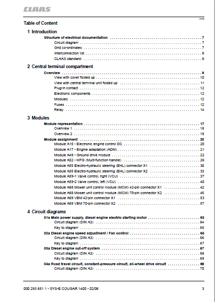
TABLE OF CONTENTS:
Class Cougar 1400 Technical Systems & Electric Service Manual – PDF DOWNLOAD
Table of Content 3
1 Introduction 7
Structure of electrical documentation 7
Circuit diagram 7
Grid co-ordinates 7
Interconnection list 8
CLAAS standard: 8
2 Central terminal compartment 9
Overview 9
View with cover folded up 10
View with central terminal unit folded up 11
Plug-in contact 12
Electronic components 12
Modules 12
Fuses 12
Relay 14
3 Modules 17
Module representation 17
Overview 1 18
Overview 2 19
Module assignment 20
Module A15 – Electronic engine control DC 20
Module A17 – Engine adaptation (ADM) 21
Module A49 – Ground drive module 22
Module A52 – MFG (Multi-function handle) 26
Module A55 Electro-hydraulic steering (EHL) connector X1 30
Module A55 Electro-hydraulic steering (EHL) connector X2 33
Module A59-1 Valve control, right (VCU) 37
Module A59-2 Valve control, left (VCU) 40
Module A68 Mower unit control module (MCM) 42-pin connector X1 42
Module A68 Mower unit control module (MCM) 70-pin connector X2 45
Module A69 VBM 42-pin connector X1 53
Module A69 VBM 70-pin connector X2 57
4 Circuit diagrams 63
01a Main power supply, diesel engine electric starting motor 63
Circuit diagram (DIN A3) 64
Key to diagram 65
02a Diesel engine speed adjustment / Fan control 65
Circuit diagram (DIN A3) 66
Key to diagram 67
03a Diesel engine cut-off system 67
Circuit diagram (DIN A3) 68
Key to diagram 69
04a Road travel circuit, constant-pressure circuit, all-wheel drive circuit 69
Circuit diagram (DIN A3) 70
Key to diagram 71
05a Terminal 71
Circuit diagram (DIN A3) 72
Key to diagram 73
06a CAN BUS, module power supply 75
Circuit diagram (DIN A3) 76
Key to diagram 77
07a Centre mower unit drive circuit 79
Circuit diagram (DIN A3) 80
Key to diagram 81
08a Front mower unit PTO shaft circuit 81
Circuit diagram (DIN A3) 82
Key to diagram 83
12a Multifunction handle 83
Circuit diagram (DIN A3) 84
Key to diagram 85
A52 Multifunction handle module 86
13a Front mower units management 87
Circuit diagram (DIN A3) 88
Key to diagram 89
14a Centre mower units management 91
Circuit diagram (DIN A3) 92
Key to diagram 93
15a Swath control (reserved) 95
Circuit diagram (DIN A3) 96
Key to diagram 97
26a Machine monitoring 97
Circuit diagram (DIN A3) 98
Key to diagram 99
27a External sensor monitoring, laser steering reserved 99
Circuit diagram (DIN A3)100
Key to diagram101
28a EHL, cab position detection, special steering programs enable103
Circuit diagram (DIN A3)104
Key to diagram105
30a Warning beacon107
Circuit diagram (DIN A3)108
Key to diagram109
33a Cab rotation109
Circuit diagram (DIN A3)110
Key to diagram111
36a Turn indicator system (Europe)113
Circuit diagram (DIN A3)114
Key to diagram115
36b Turn indicator system (USA)117
Circuit diagram (DIN A3)118
Key to diagram119
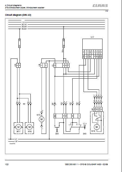
37a Windscreen wiper, Windscreen washer121
Circuit diagram (DIN A3)122
Key to diagram123
38a Compressor-type air conditioner123
Circuit diagram (DIN A3)124
Key to diagram125
39a Operator’s seat125
Circuit diagram (DIN A3)126
Key to diagram127
40a Additional sockets127
Circuit diagram (DIN A3)128
Key to diagram129
41a Drive management, parking brake, cab position, differential lock129
Circuit diagram (DIN A3)130
Key to diagram131
42a Limp Home131
Circuit diagram (DIN A3)132
Key to diagram133
43a Electronic ground drive, cab position detection133
Circuit diagram (DIN A3)134
Key to diagram135
44a Transmission control135
Circuit diagram (DIN A3)136
Key to diagram137
45a Lighting main circuit, taillight, position light137
Circuit diagram (DIN A3)138
Key to diagram139
46a Low beam, high beam, low beam changeover switch139
Circuit diagram (DIN A3)140
Key to diagram141
47a Worklights I143
Circuit diagram (DIN A3)144
Key to diagram145
49a Transmission control147
Circuit diagram (DIN A3)148
Key to diagram149
50a Instrument lighting, broadcast radio, mirror adjustment149
Circuit diagram (DIN A3)150
Key to diagram151
5 Diagnosis153
Diagnosis according to fault code153
Fault code CCN (CLAAS Component Number)153
Circuit diagram structure165
FMI fault code (fault mode indicator)167
6 Location of components171
Overview (DIN A3)171
Figures171
Index173
A173
B173
C173
D173
E173
F173
G173
H173
I173
L173
M173
O174
P174
R174
S174
T174
W174
IMAGES PREVIEW OF THE MANUAL:
CLASS COUGAR 1400 TECHNICAL SYSTEMS & ELECTRIC SERVICE MANUAL – PDF DOWNLOAD:
PLEASE NOTE:
- This is the SAME exact manual used by your dealers to fix your vehicle.
- The same can be yours in the next 2-3 mins as you will be directed to the download page immediately after paying for the manual.
- Any queries / doubts regarding your purchase, please feel free to contact [email protected]
S.M