Covidien Force EZ Electrosurgical Generator C 8C Service Manual PDF
Original price was: $95.00.$30.95Current price is: $30.95.
Official Covidien factory service manual for the Force EZ Electrosurgical Generator models C and 8C. Complete 256-page technical documentation covering Instant Response Technology, REM Contact Quality Monitoring System, bipolar/monopolar surgical modes, RF power output circuits, safety systems, calibration procedures, troubleshooting protocols, component replacement, and preventive maintenance. Essential service manual for biomedical engineers, hospital clinical engineering, and authorized electrosurgical equipment technicians.
Description
Covidien Force EZ Electrosurgical Generator C 8C Service Manual PDF DOWNLOAD
DESCRIPTION
Covidien Force EZ Electrosurgical Generator C/8C – Official Factory Service Manual
This is the complete, official Covidien factory service manual for the Force EZ Electrosurgical Generator models C and 8C. With 256 comprehensive pages of detailed technical information, this manual provides everything needed for professional maintenance, calibration, repair, and troubleshooting of these critical electrosurgical systems used in operating rooms worldwide.
FILE DETAILS
- Manual Number: 1017171
- Equipment Covered:
- Force EZ Electrosurgical Generator C
- Force EZ Electrosurgical Generator 8C
- Manufacturer: Covidien (formerly Valleylab)
- Compliance: European Communities Council Directive 93/42/EEC, Medical Device Directive
- PDF Quality: High-quality optimized professional documentation
- Total Pages: 256 Pages
- File Size: 5.9 MB
- Format: Letter size (8.5″ x 11″)
- Classification: Confidential Service Manual – Qualified Technicians Only
EQUIPMENT OVERVIEW
The Force EZ Electrosurgical Generator C/8C is an isolated output electrosurgical system that provides radiofrequency (RF) power for cutting, desiccating, and fulgurating tissue during surgical procedures.
Key Technologies:
- Instant Response Technology – Automatically senses tissue resistance and adjusts current/voltage for consistent surgical effect
- REM Contact Quality Monitoring System – Protects patients against burns at return electrode site
- Bipolar Mode – Standard mode for most bipolar applications with low voltage continuous current
- Monopolar Cut Modes – Pure and Blend modes for diverse surgical applications
- Monopolar Coag Modes – Low (desiccate) and High (fulgurate) settings for controlled coagulation
- Force GSU and Argon Gas Delivery Unit II Compatibility
Surgical Applications:
- Bipolar electrosurgery for delicate tissue work
- Monopolar cutting with hemostasis control
- Tissue desiccation without sparking
- Tissue fulguration for larger area coagulation
- Compatible with wide range of electrosurgical accessories
COMPREHENSIVE MANUAL COVERAGE
CHAPTER 1: SERVICE PERSONNEL SAFETY
- Safety Information:
- Critical safety requirements for service personnel
- Properly trained service staff requirements
- Safety-conscious service procedures
- Warnings, Cautions, and Notices:
- General Safety:
- Patient safety during self-test completion
- Single instrument connection rules
- Equipment stacking precautions
- Activation tone requirements
- Hospital equalization connector requirements
- Proper voltage connection procedures
- Active Accessories:
- Proper receptacle connection requirements
- REM safety feature requirements for patient return electrodes
- Fire/Explosion Hazards:
- Flammable anesthetic environment restrictions
- Active electrode fire hazards
- Extension cord prohibitions
- Fuse replacement specifications
- Electric Shock Hazards:
- Grounding requirements
- Power cord safety
- Energy dissipation waiting periods (5 minutes after power disconnect)
- Cleaning safety procedures
- Exposed wiring precautions
- Grounding strap usage guidelines
- One-hand rule and isolated tool requirements
- AC/DC voltage hazards in line circuitry
- High frequency RF signal burn hazards
- Servicing Precautions:
- ESD (Electrostatic Discharge) protection requirements
- Static-control workstation requirements
- Circuit board handling procedures
- Antistatic container requirements
- Low voltage power supply verification after installation
- Calibration Safety:
- RF current coupling and shunting prevention (4″ minimum distance from metal)
- Resistor body contact prevention
- Calibration value saving procedures
- Load resistor limitations during calibration
- Post-calibration self-test requirements
- Battery replacement calibration requirements
- Control board replacement calibration
- Heat sink replacement calibration
- Power Supply/RF board replacement calibration
- Cleaning Precautions:
- Abrasive compound restrictions
- Solvent damage prevention
- General Safety:
CHAPTER 2: INTRODUCTION
- General Description:
- Isolated output electrosurgical generator overview
- Bipolar and monopolar electrosurgery capabilities
- Complete feature set description
- List of Components:
- Main enclosure (cover and base)
- Power cord specifications
- Front panel components
- Rear panel components
- Internal components inventory
- Handle location
- Instant Response Technology:
- Automatic tissue resistance sensing
- Current and voltage adjustment algorithms
- Constant current, constant power, constant voltage operation
- Maximum output voltage control
- Capacitive coupling reduction
- Video interference minimization
- Sparking reduction technology
- Mode-specific application details
- Bipolar Modes:
- Standard bipolar mode characteristics
- Low voltage continuous current for delicate tissue
- Desiccation without sparking
- Voltage limiting at high tissue resistance
- Protection against sparking as tissue dries
- Monopolar Cut and Coag Modes:
- Cut Modes:
- Pure mode: even cutting with minimal hemostasis
- Blend mode: cutting with additional hemostasis
- Wide range power settings for diverse applications
- Coag Modes:
- Low (desiccate) mode: three settings for tissue dehydration
- High (fulgurate) mode: two settings for larger area coagulation
- Area size and penetration depth control
- Cut Modes:
- REM Contact Quality Monitoring System:
- Patient safety burn prevention at return electrode site
- Continuous resistance measurement (5-135 ohms safe range)
- Individual patient adaptation with baseline resistance
- 40% increase threshold alarm activation
- Automatic power output cessation during alarm
- Non-REM electrode monitoring (pin-to-pin resistance only)
- Broken wire and connector detection
- Special Features:
- Low (Desiccate) Coag Settings:
- Low 1: standard desiccation with minimal cutting/sparking
- Low 2: lowest voltage desiccation (≤ 200 Vrms)
- Low 3: slightly higher voltage (≤ 300 Vrms) with comparable desiccation
- High (Fulgurate) Coag Settings:
- High 1: smaller area coagulation without tissue contact
- High 2: larger area coagulation without tissue contact
- Recall Function: Most recently used modes and power settings
- Default Coag Mode: User-selectable low or high default
- Original Default Settings: Factory reset capability
- Low (Desiccate) Coag Settings:
CHAPTER 3: CONTROLS, INDICATORS, AND RECEPTACLES
- Front Panel Description:
- Power switch location and function
- Mode and output power controls
- Footswitch receptacle
- Bipolar/accessory output selection button
- Electrosurgical accessory receptacles
- Mode selection indicators
- Patient return electrode status indicators
- LED displays and seven-segment readouts
- Rear Panel Description:
- Power entry module
- Volume control for activation tone
- Two footswitch receptacles
- Equipotential grounding lug
- Option panel access
- Fuse drawer location
- Serial port connections
- Option Panel:
- RF activation port
- Serial communication interface
- Accessory connections
CHAPTER 4: TECHNICAL SPECIFICATIONS
- Performance Characteristics:
- General Specifications:
- Equipment classification and ratings
- Operational modes and capabilities
- Dimensions and Weight:
- Physical size specifications
- Weight for transport and mounting
- Operating Parameters:
- Temperature range: Operating and storage
- Humidity specifications
- Altitude limitations
- Environmental conditions
- Transport and Storage:
- Temperature limits
- Humidity requirements
- Packaging requirements
- Duty Cycle:
- Continuous operation specifications
- Thermal management parameters
- Cool-down requirements
- Internal Memory:
- Data storage capabilities
- Calibration constant storage
- User setting retention
- Battery backup requirements
- Audio Volume:
- Activation tone specifications
- Adjustable volume range
- Alarm tone characteristics
- REM Contact Quality Monitor:
- Resistance measurement range (5-135 ohms)
- Baseline resistance adaptation
- 40% increase threshold specifications
- Alarm activation criteria
- Serial Port:
- Communication protocol specifications
- Baud rate and data format
- Connector pinout
- RF Activation Port:
- Remote activation capabilities
- Signal specifications
- Connector details
- Input Power:
- Voltage requirements (100-240V AC)
- Frequency specifications (50/60 Hz)
- Current consumption
- Power factor
- Power Cord Specification:
- Wire gauge requirements
- Connector types
- Length specifications
- Regional variants
- Low Frequency (50-60 Hz) Leakage Current:
- Normal condition measurements
- Single fault condition limits
- Patient leakage specifications
- Applied part leakage
- High Frequency (RF) Leakage Current:
- Measurement procedures
- Acceptable limits
- Test conditions
- General Specifications:
- Standards and IEC Classifications:
- Class I Equipment (IEC 60601-1): Grounding requirements
- Type CF Equipment (IEC 60601-1): Defibrillator proof specifications
- Liquid Spillage (IEC 60601-2-2 Clause 44.3): Protection rating
- Electromagnetic Interference: EMI emission limits
- Electromagnetic Compatibility (IEC 60601-1-2 and IEC 60601-2-2):
- Immunity testing requirements
- Emission standards compliance
- Voltage Transients: Emergency generator mains transfer specifications
- Output Characteristics:
- Available Power Settings in Watts:
- Bipolar mode: 1-70W
- Cut modes: 1-300W
- Coag modes: 1-120W
- Setting increment specifications
- Maximum Output Specifications:
- Voltage limits for each mode
- Current limits
- Power limits across resistance ranges
- Output Waveforms:
- Pure cut waveform characteristics
- Blend cut waveform
- Bipolar waveform
- Low coag waveforms (settings 1, 2, 3)
- High coag waveforms (settings 1, 2)
- Frequency specifications
- Duty cycle percentages
- Available Power Settings in Watts:
- Output Power vs. Resistance Graphs:
- Bipolar output characteristics (50-3000 ohms)
- Monopolar cut graphs (pure and blend modes)
- Monopolar coag graphs (all five settings)
- Power curves across full resistance range
- Constant current, constant power, constant voltage regions
- Output Power vs. Generator Settings:
- Calibration curves
- Linearity specifications
- Setting-to-output correlation
CHAPTER 5: PRINCIPLES OF OPERATION
- Functional Overview:
- Complete system architecture
- Component interaction principles
- Signal flow diagrams
- Control Board:
- Microcontrollers:
- Primary and secondary processor functions
- Program execution and control
- Watchdog timer operation
- Shared RAM: Inter-processor communication
- Real-time Clock: Time and date management
- I/O Expansion: Digital input/output control
- Keyboard Interface and Activation Inputs: Front panel control processing
- Power Supply Supervisor Circuit: Voltage monitoring and reset control
- A/D and D/A Conversion: Analog signal processing
- Waveform Generation (T_ON ASIC): Custom IC for RF waveform synthesis
- T_ON Average Check: Safety verification algorithm
- Audio Alarm: Tone generation and control
- Serial Interface: External communication protocols
- Dosage Error Algorithm: Safety monitoring for output delivery
- Instant Response Algorithm: Tissue impedance response system
- Microcontrollers:
- Display Board:
- Bipolar, Cut, and Coag Power Setting Encoders: Rotary encoder processing
- RF Indicator Lamps: Visual activation feedback
- LED and Seven-segment Display Drivers: Numerical and mode displays
- Mode Selection Switches: User input processing
- REM Switch Circuit: Return electrode monitoring enable/disable
- Front Panel Footswitch Circuit: Activation input processing
- Footswitch Board:
- Dual footswitch input processing
- Cut and coag activation circuits
- Debouncing and signal conditioning
- Power Supply/RF Board:
- Power Supply/RF Board Interfaces:
- Control board connections
- Display board connections
- External connections
- High Voltage Power Supply:
- Switching power supply design
- Voltage regulation circuits
- 340VDC output for RF stage
- Overcurrent protection
- Thermal management
- Low Voltage Power Supply:
- +15V, +5V, -15V outputs
- Digital and analog supply isolation
- Voltage regulation and filtering
- RF Output Stage:
- Class E resonant amplifier design
- MOSFET switching circuits
- Output transformer and matching network
- Power control algorithms
- Spark gap protection
- Spark Control Circuit:
- Arc detection and suppression
- Tissue char prevention
- RF Leakage Sensing and Reduction Circuit:
- Leakage current monitoring
- Active reduction techniques
- REM Circuit:
- Contact quality measurement
- Resistance monitoring algorithms
- Alarm activation logic
- IsoBloc Circuit:
- Output isolation verification
- Patient safety protection
- Audio Circuit:
- Activation tone generation
- Alarm tone synthesis
- Volume control
- Footswitch Decode Circuit:
- Remote footswitch identification
- Function assignment logic
- Temperature Sense Circuit:
- Heat sink monitoring
- Thermal shutdown protection
- Power Supply/RF Board Interfaces:
CHAPTER 6: SETUP, TESTS, AND ADJUSTMENTS
- Setting up the Generator:
- Initial installation procedures
- Power connection verification
- Grounding requirements
- Accessory connections
- Connections for Bipolar Surgery:
- Bipolar instrument connection
- Footswitch setup
- Power setting procedures
- Connections for Monopolar Surgery:
- Active electrode connection
- Patient return electrode placement
- REM electrode verification
- Setting cut and coag output
- Using Two Generators Simultaneously:
- Interference prevention
- Proper spacing requirements
- Setting Up the Special Features:
- Accessing setup mode
- Configuring recall function
- Setting default coag mode
- Restoring original defaults
- Changing Modes and Power Settings:
- Mode selection procedures
- Power adjustment protocols
- Display verification
- Activating the Surgical Instrument:
- Footswitch activation
- Front panel activation button
- Visual and audio feedback
- Periodic Safety Check:
- Recommended Test Equipment:
- Electrosurgical analyzer specifications
- Multimeter requirements
- Oscilloscope for waveform analysis
- Leakage current analyzer
- Ground resistance tester
- Calibrated load resistors
- Inspecting the Generator and Accessories:
- Visual inspection checklist
- Power cord examination
- Connector inspection
- Cable integrity verification
- Inspecting the Internal Components:
- Cover removal procedures
- Circuit board inspection
- Connection verification
- Dust and debris removal
- Testing the Generator:
- Power-on self-test verification
- Mode selection testing
- Display function verification
- Audio tone testing
- Verifying REM Function:
- REM electrode connection test
- Resistance measurement verification
- Alarm activation testing
- Non-REM electrode testing
- Confirming Outputs:
- Power output verification across all modes
- Waveform analysis procedures
- Load resistor testing protocols
- Output accuracy verification
- Checking Low Frequency Leakage Current:
- Earth leakage testing
- Enclosure leakage
- Patient leakage measurements
- Applied part leakage
- Acceptable limits
- Checking High Frequency Leakage Current:
- RF leakage measurement procedures
- Active electrode leakage
- Return electrode leakage
- Acceptable limits
- Recommended Test Equipment:
- Calibrating the Generator:
- Preparing for Calibration:
- Required test equipment
- Calibration load resistors
- Environmental requirements
- Entering Calibration Mode:
- Special button sequence
- Calibration menu navigation
- Exiting Calibration Mode:
- Saving calibration data
- Self-test initiation
- Calibration Step 1: Verify generator data (model, serial number, firmware)
- Calibration Step 2: Adjust calendar (date setting)
- Calibration Step 3: Adjust clock (time setting)
- Calibration Step 4: Check REM impedance measurement accuracy
- Calibration Step 5: Check and adjust current sense gain with precision resistors
- Calibration Step 6: Check and adjust voltage sense gain across modes
- Calibration Step 7: Check and adjust reactance gain for tissue impedance
- Calibration Step 8: Check and adjust ECON factor for energy delivery
- Preparing for Calibration:
CHAPTER 7: TROUBLESHOOTING
- Inspecting the Generator:
- Initial diagnostic procedures
- Systematic approach to fault isolation
- Visual inspection guidelines
- Correcting Malfunctions:
- Symptom-based troubleshooting tables
- Power supply problems
- No output conditions
- Incorrect output power
- Display malfunctions
- Control failures
- Footswitch issues
- REM system faults
- Audio system problems
- Intermittent operation
- Systematic component isolation
- Responding to System Alarms:
- REM contact quality alarms
- Dosage error alarms
- Temperature alarms
- Hardware fault alarms
- Self-test failure alarms
- Alarm code interpretation
- Corrective action procedures
- Correcting Integrated Circuit (IC) Malfunctions:
- IC identification procedures
- Testing protocols
- Replacement guidelines
- Socket-mounted vs. soldered ICs
- ESD precautions during replacement
CHAPTER 8: REPLACEMENT PROCEDURES
- Interconnect Diagram:
- Complete internal wiring schematic
- Cable routing diagrams
- Connector identification
- Battery Replacement:
- Real-time clock battery location
- Removal procedures
- Installation instructions
- Post-replacement calibration requirements
- Control Board Replacement:
- Board removal procedures
- Cable disconnection sequence
- Installation instructions
- Calibration requirements
- Display Board Replacement:
- Removal procedures with detailed photos
- Cable routing
- Installation sequence
- Seven-segment LED replacement
- Footswitch Board Assembly:
- Board location and access
- Removal procedures
- Installation guidelines
- Front Panel Replacement:
- Complete assembly removal
- Component-level service
- Reassembly procedures
- Front Panel Components:
- Footswitch receptacle replacement
- Power setting knob removal
- Power switch replacement
- REM lever service
- Fuses:
- Fuse drawer fuse replacement
- Low voltage power supply fuse
- Power Supply/RF board fuse
- Proper fuse specifications
- Handle Replacement:
- Removal procedures
- Installation instructions
- Heat Sink Components:
- Left Front Heat Sink:
- MOSFET replacement
- Thermal compound application
- Torque specifications
- Left Rear Heat Sink:
- Component replacement
- Mounting procedures
- Right Heat Sink:
- Power device replacement
- Thermal management
- Left Front Heat Sink:
- Low Voltage Power Supply:
- Complete removal procedure
- Installation guidelines
- Post-installation voltage verification
- Power Entry Module:
- Fuse and filter replacement
- Line cord connection
- Installation procedures
- Power Supply/RF Board:
- Complete board and heat sink removal
- Installation procedures
- Calibration requirements
- Thermal compound application
CHAPTER 9: REPAIR POLICY AND PROCEDURES
- Responsibility of the Manufacturer:
- Warranty coverage details
- Covidien service obligations
- Authorized service centers
- Returning the Generator for Service:
- Step 1: Obtain return authorization number
- Step 2: Clean and decontaminate the generator
- Step 3: Proper packaging and shipping procedures
- Circuit Boards:
- Repair vs. replace policies
- Board-level service limitations
- Service Centers:
- Authorized service center locations
- Contact information
- Technical support resources
CHAPTER 10: SERVICE PARTS
- Ordering Replacement Parts:
- Part number system
- Ordering procedures
- Authorized distributors
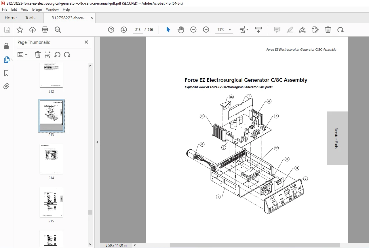
- Force EZ Generator Assembly:
- Complete assembly diagrams
- Major component identification
- Generator Assembly Parts List:
- Complete itemized parts catalog
- Part numbers and descriptions
- Quantity per assembly
- Control Board Components:
- IC part numbers
- Passive component values
- Connector specifications
- Footswitch Board Components:
- Component identification
- Replacement part numbers
- Power Supply/RF Board Components:
- Power device part numbers
- Transformer specifications
- Capacitor ratings
- MOSFET specifications
WARRANTY COVERAGE
Limited Warranty Period:
- Electrosurgical Generators: One year from date of shipment
- Mounting Fixtures: One year from date of shipment
- Footswitches: One year from date of shipment
- Reusable Instruments: One year from date of shipment
Warranty Provisions:
- Repair or replacement at Covidien’s option
- Covers defects in material and workmanship
- Normal use and service conditions
- Non-transferable to subsequent owners
Warranty Exclusions:
- Unauthorized repairs or alterations
- Misuse, neglect, or accident damage
- Improper maintenance
REGULATORY COMPLIANCE
Safety Standards:
- IEC 60601-1: Medical Electrical Equipment – General Requirements
- IEC 60601-2-2: Particular Requirements for Electrosurgical Equipment
- IEC 60601-1-2: Electromagnetic Compatibility Requirements
- European Medical Device Directive 93/42/EEC
Equipment Classifications:
- Class I Equipment (with protective earth)
- Type CF Applied Part (cardiac floating, defibrillator proof)
- IPX1 Protection against dripping water
IDEAL FOR:
- Hospital biomedical engineering departments
- Clinical engineering technicians
- Medical equipment service companies
- Authorized Covidien/Valleylab service centers
- Independent biomedical equipment technicians (IBETs)
- Operating room technical staff
- Surgical services technical support
- Medical device training institutions
- Healthcare facility maintenance departments
- Military medical facility technicians
- International healthcare technical services
WHY THIS MANUAL IS ESSENTIAL:
The Force EZ Electrosurgical Generator is critical life-support equipment used daily in surgical procedures. This comprehensive 256-page service manual provides:
✓ Patient Safety – Proper REM system maintenance prevents return electrode burns
✓ Regulatory Compliance – Meet required IEC and medical device standards
✓ Accurate Calibration – Eight-step calibration ensures precise power delivery
✓ Complete Troubleshooting – Systematic fault diagnosis minimizes downtime
✓ Safety Testing – Comprehensive leakage current and ground resistance procedures
✓ Component Replacement – Detailed step-by-step replacement procedures
✓ Output Verification – Waveform analysis and power accuracy confirmation
✓ Preventive Maintenance – Scheduled inspection and testing protocols
CRITICAL MEDICAL DEVICE NOTICE:
This service manual is intended for use by qualified biomedical engineers and factory-trained service technicians only. Servicing electrosurgical equipment requires:
- Thorough understanding of RF power systems and safety
- Specialized test equipment (electrosurgical analyzer, RF load resistors)
- Knowledge of IEC 60601 medical device standards
- ESD protection procedures for sensitive electronics
- Proper calibration tools and procedures
- Understanding of patient safety monitoring systems
- Compliance with hospital and regulatory requirements
WARNING: Improper service or calibration can result in:
- Inaccurate power delivery causing patient tissue damage
- REM system malfunction leading to return electrode burns
- Electrical shock hazards to patients and operators
- Fire hazards in the surgical environment
- Equipment damage or failure during critical procedures
Always follow manufacturer safety warnings, use proper test equipment, and verify all safety systems after service.
Ensure your Force EZ Electrosurgical Generator operates safely and accurately! This official Covidien factory service manual provides the same comprehensive information used by factory-trained technicians. With instant PDF download, qualified biomedical engineers can access this 256-page technical resource immediately. Whether performing periodic safety checks, calibrating the RF output, troubleshooting system alarms, or replacing critical components, this manual is your authoritative technical reference for professional electrosurgical equipment service.