
Covidien Force FX Electrosurgical Generator C Service Manual PDF Instant Response PDF
Original price was: $85.00.$19.95Current price is: $19.95.
Official Covidien service manual for Force FX Electrosurgical Generator C with Instant Response technology. This comprehensive 246-page technical manual (part 1 of 2) covers installation, operation, periodic safety checks, calibration, troubleshooting, and repair for this advanced ESU system. Includes REM Contact Quality Monitoring, bipolar/monopolar modes, CUSA compatibility, system alarms, replacement procedures, calibration protocols, RS-232 commands, and complete service parts information for qualified biomedical technicians.
Description
Covidien Force FX Electrosurgical Generator C Service Manual PDF Instant Response – PDF DOWNLOAD
DESCRIPTION
This is the official Covidien Force FX Electrosurgical Generator C Service Manual (Part 1 of 2 – Text portion, with separate Schematics Supplement as Part 2 of 2). This comprehensive 246-page technical manual provides complete service information for qualified biomedical engineers and technicians to install, test, calibrate, troubleshoot, and repair this advanced electrosurgical unit used in surgical procedures worldwide.
Product Overview
Covidien Force FX Electrosurgical Generator C:
The Force FX C is an isolated output electrosurgical generator designed to provide precise RF (radio frequency) power for cutting, desiccating, and fulgurating tissue during bipolar and monopolar surgical procedures.
Key Applications:
- General surgery
- Laparoscopic procedures
- Gynecological surgery
- Urological procedures
- Plastic and reconstructive surgery
- ENT (ear, nose, throat) surgery
- Orthopedic surgery
- Neurosurgery
- Cardiovascular surgery
Advanced Features and Technologies
Instant Response™ Technology:
- Rapid tissue impedance adaptation
- Consistent surgical performance
- Reduced thermal spread
- Enhanced surgical precision
REM™ Contact Quality Monitoring System:
- Real-time patient return electrode monitoring
- Contact quality assessment
- Safety alarm system
- Reduces risk of patient burns
Operating Modes:
Bipolar Modes:
- Precise (Low) – Fine coagulation control
- Standard (Medium) – General bipolar surgery
- Macro (Macrobipolar) – Large vessel sealing
Monopolar Cut Modes:
- Low – Minimal tissue damage cutting
- Pure – Clean cutting with minimal hemostasis
- Blend – Cutting with hemostasis
Monopolar Coag Modes:
- Desiccate (Low) – Direct tissue coagulation
- Fulgurate (Medium) – Medium spray coagulation
- Spray (High) – Non-contact surface coagulation
Simultaneous Coagulation:
- Simultaneous cut and coag capability
- Independent power control
- Enhanced surgical efficiency
CUSA EXcel™ System Compatibility:
- Supports CUSA™ handpiece with CEM™ nosecone
- Ultrasonic electrosurgery capability
- Combined ultrasonic and RF energy
- Simultaneous coag with CUSA system
Technical Specifications
Power Requirements:
- Input Voltage: 110 V ~ Nominal / 230 V ~ Nominal (auto selected)
- Auto-voltage selection – Worldwide compatibility
- Frequency: 50/60 Hz
- Power Consumption: Specifications for maximum draw
RF Output:
- High frequency RF energy
- Isolated output design
- Multiple output receptacles
- Adjustable power settings
Activation Methods:
- Handswitch activation (on instruments)
- Footswitch activation (three footswitch receptacles)
- RF activation port
- Recall function for last-used settings
Safety Features:
- REM Contact Quality Monitoring System
- Comprehensive alarm system
- Isolated output circuitry
- Overtemperature protection
- Self-test on power-up
- Audible activation tone (adjustable volume)
Connectivity:
- RS-232 Serial Port – Computer interface for calibration/service
- RF Activation Port – External activation control
- Expansion Port – Future upgrades
- Three Footswitch Receptacles – Multiple footswitch support
- Equipotential Grounding Lug – OR table grounding
Compatible Accessories:
- Valleylab™ Argon Gas Delivery Unit II
- CUSA EXcel™ ultrasonic system
- Various monopolar and bipolar instruments
- REM™ patient return electrodes
- Standard patient return electrodes
Comprehensive Manual Contents
DOCUMENT INFORMATION:
- Manual Type: Service Manual (Part 1 of 2 – Text)
- Separate Schematics Supplement: Part 2 of 2
- Creator: FrameMaker 10.0.2
- Updated: November 2, 2016
REGULATORY COMPLIANCE:
- Medical Device Directive: 93/42/EEC
- European Communities Council Directive compliant
PREFACE
Target Audience:
- Qualified medical professionals
- Trained biomedical technicians
- Authorized service personnel
Manual Structure:
- Part 1: Complete service procedures and information
- Part 2: Electrical schematics and circuit diagrams (separate)
Conventions Used:
- WARNING – Risk of death or serious injury
- PRECAUTION – Risk of minor/moderate injury
- NOTICE – Risk of product damage
- IMPORTANT – Operating tips and maintenance suggestions
LIMITED WARRANTY
Warranty Coverage:
- Electrosurgical Generators: One year from shipment date
- Mounting Fixtures: One year from shipment date
- Footswitches: One year from shipment date
- Sterile Single Use Items: Sterility as stated on packaging
- Patient Return Electrodes: Shelf life as stated on packaging
Warranty Limitations:
- Non-transferable to subsequent owners
- Limited to repair or replacement
- Excludes unauthorized modifications
- Excludes misuse, neglect, or accident damage
SOFTWARE LICENSE
License Grant:
- Single user, non-exclusive license
- Non-transferable, revocable license
- Machine-readable object code only
- Single CPU usage only
Restrictions:
- No decompiling or reverse engineering
- No modifications or derivative works
- No distribution or sublicensing
- Confidential and proprietary software
Software Warranty:
- Performs as documented
- Warranty period: Longer of product warranty or 90 days
- Remedy limited to replacement or refund
CHAPTER 1: INTRODUCTION
General Description:
- Isolated output electrosurgical generator
- Instant Response technology
- Multiple bipolar and monopolar modes
- REM Contact Quality Monitoring
- CUSA compatibility
- Simultaneous coagulation support
- Recall function
- Adjustable activation tone
List of Components:
Front Panel Components:
- Power switch
- Mode and power controls
- Recall button
- Bipolar instrument receptacle
- Monopolar 1/CEM instrument receptacle
- Monopolar 2 instrument receptacle
- Patient return electrode receptacle
- REM alarm indicator
- CEM indicator
- Mode and power displays
Rear Panel Components:
- Volume control (activation tone)
- Three footswitch receptacles
- Power entry module
- Equipotential grounding lug
- RS-232 serial port
- RF activation port
- Expansion port
- Cooling vents
Internal Components:
- Control (microcontroller) board
- Display board
- Footswitch board
- Power Supply/RF board
- Low voltage power supply
- Cooling fan
- Heat sinks (left front, left rear, right)
- Battery (for RAM backup)
Service Personnel Safety:
General Safety: ⚠ Complete self-test before use
⚠ One instrument per receptacle only
⚠ Do not stack equipment
⚠ Provide distance from other electronics
⚠ Keep activation tone audible
⚠ Connect to proper voltage
⚠ Use equipotential grounding if required
Active Accessories Safety: ⚠ No wet accessories
⚠ Ensure proper connections
⚠ Connect to proper receptacle types
⚠ Set power to lowest before testing
⚠ Bipolar: Activate only with forceps on tissue
Fire/Explosion Hazards: ⚠ No flammable anesthetics present
⚠ Keep active accessories from flammable materials
⚠ Use holster for hot accessories
⚠ No extension cords
⚠ Replace fuses with same type/rating
Electric Shock Hazards: ⚠ Properly grounded receptacle required
⚠ No power plug adapters
⚠ No wet power cords
⚠ Wait 5 minutes after power off before servicing
⚠ Turn off and unplug before cleaning
⚠ No exposed wiring contact when energized
⚠ No grounding strap on energized generator
⚠ Use isolated tools and “one hand rule”
⚠ Lethal AC/DC voltages present in line and HV circuits
⚠ High frequency, high voltage in RF output stage
Servicing Precautions: ⚠ Read all warnings before servicing
⚠ ESD-sensitive components – use static control
⚠ Wear grounding strap (except on energized units)
⚠ Handle boards by edges
⚠ Use antistatic containers
⚠ Verify voltages after power supply replacement
Calibration Precautions: ⚠ Keep resistors 4″ from metal surfaces
⚠ Save values after each calibration step
⚠ Load restrictions during calibration
⚠ No adjustments while generator activated
⚠ Self-test required after calibration
⚠ Recalibrate after battery replacement
⚠ Recalibrate after Control board replacement
⚠ Recalibrate after heat sink work
⚠ Recalibrate after Power Supply/RF board replacement
CHAPTER 2: CONTROLS, INDICATORS, AND RECEPTACLES
Front Panel Layout: Complete description with illustrations:
- Power switch location and operation
- Recall button function
- Bipolar controls and display
- Cut mode controls and display
- Coag mode controls and display
- Bipolar instrument receptacle
- Monopolar 1/CEM instrument receptacle
- Monopolar 2 instrument receptacle
- Patient return electrode receptacle
- REM alarm indicator
- CEM indicator
- Mode selection buttons
- Power adjustment controls
- Digital power displays
Rear Panel Layout:
- Volume control (activation tone adjustment)
- Footswitch receptacles (3 positions)
- Power entry module
- Fuse drawer
- Equipotential grounding lug
- RS-232 serial port (DB-9 connector)
- RF activation port
- Expansion port
- Cooling fan and vents
- Equipment labeling
CHAPTER 3: SPECIFICATIONS
Complete technical specifications including:
- AC power input specifications
- RF output specifications
- Bipolar output ranges
- Monopolar cut output ranges
- Monopolar coag output ranges
- Frequency specifications
- Impedance ranges
- Cooling requirements
- Environmental specifications
- Safety classifications
- EMC compliance
- Dimensions and weight
CHAPTER 4: PRINCIPLES OF OPERATION
System Overview:
- Block diagram of generator
- Signal flow description
- Component interaction
Control Board:
- Microcontroller functions
- Memory (RAM with battery backup)
- Input/output processing
- Mode control logic
- Power control algorithms
- Safety monitoring
- Self-test routines
- Calibration data storage
Display Board:
- Seven-segment LED displays
- Power level indicators
- Mode indicators
- Alarm indicators
- Display driver circuits
Footswitch Board:
- Footswitch input processing
- Three footswitch channels
- Activation logic
- Safety interlocks
Power Supply/RF Board:
- AC input rectification
- High voltage DC generation
- RF oscillator
- RF amplification
- Output stage
- Current and voltage sensing
- Impedance monitoring
- Output isolation
Low Voltage Power Supply:
- Multiple DC voltage outputs
- +5V, +15V, -15V, +24V rails
- Voltage regulation
- Protection circuits
REM System:
- REM oscillator
- Contact quality monitoring
- Alarm generation
- Safety logic
Heat Sink Assemblies:
- Left front heat sink components
- Left rear heat sink components
- Right heat sink components
- Thermal management
CHAPTER 5: INSTALLATION, OPERATION, AND CALIBRATION
Connections for Bipolar Surgery:
- Bipolar forceps connection
- Footswitch connection
- Setting bipolar output power
Connections for Monopolar Surgery:
- Patient return electrode connection
- Monopolar instrument connection
- REM electrode requirements
- Setting cut and coag modes
- Power adjustment
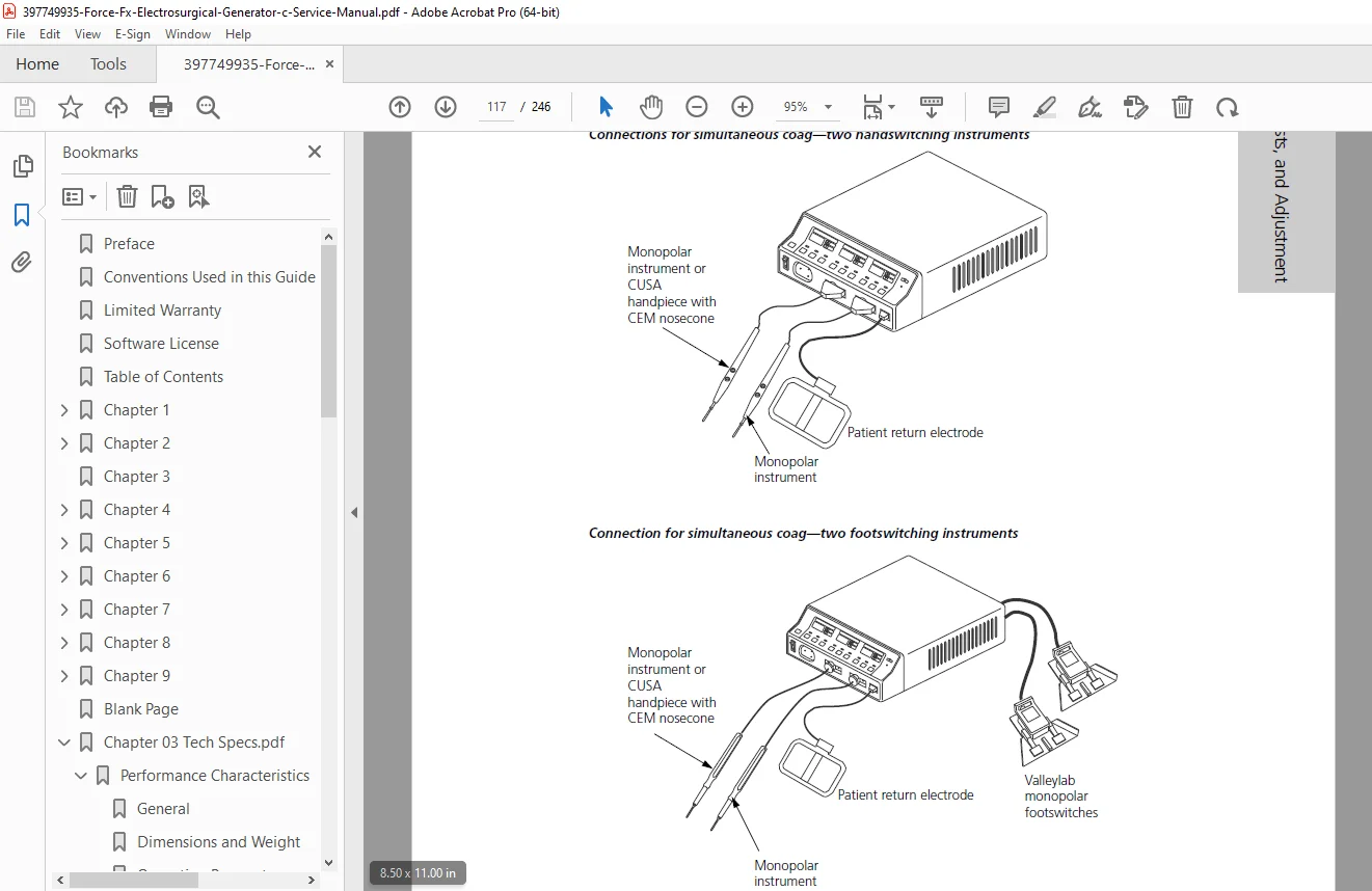
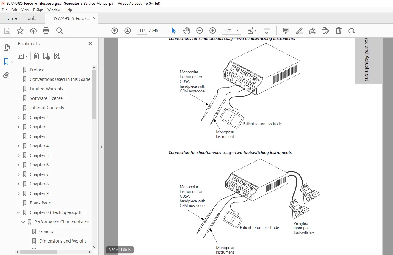
Simultaneous Coag:
- Setup procedures
- Operation guidelines
- Power coordination
Using Two Generators Simultaneously:
- Configuration requirements
- Safety considerations
CUSA Handpiece with CEM Nosecone:
- Connection procedures
- CEM indicator operation
- Output power setting
- Simultaneous coag with CUSA
Activation Methods:
- Handswitch activation
- Footswitch activation
- RF activation port usage
Periodic Safety Check:
- Recommended interval
- Recommended Test Equipment:
- Digital multimeter
- ESU analyzer (e.g., BC Biomedical ESA615 or equivalent)
- Load resistors (various values)
- Safety analyzer
- Oscilloscope (optional)
Inspection Procedures:
- Inspecting Generator and Accessories:
- Visual inspection
- Cable and cord condition
- Receptacle integrity
- Panel condition
- Inspecting Internal Components:
- Board condition
- Connection security
- Heat sink cleanliness
- Fan operation
Testing Procedures:
- Testing the Generator:
- Power-up sequence
- Self-test verification
- Display checks
- Control function tests
- Verifying REM Function:
- REM alarm test
- Contact quality monitoring test
- Electrode simulation
Confirming Outputs:
- Checking Bipolar Output:
- Power accuracy at various settings
- All three bipolar modes
- Waveform verification
- Checking Monopolar Cut Modes:
- Low, Pure, and Blend modes
- Power accuracy
- Impedance response
- Checking Monopolar Coag Modes:
- Desiccate, Fulgurate, and Spray modes
- Power accuracy
- Arc characteristics
Safety Tests:
- Checking Low Frequency Leakage Current:
- Chassis leakage
- Ground resistance
- Patient leakage (all configurations)
- Checking High Frequency Leakage Current:
- RF leakage measurements
- Isolation verification
Calibrating the Generator:
Preparation:
- Required equipment list
- Test setup configuration
- Safety precautions
Calibration Mode:
- Entering Calibration Mode:
- Key sequence
- Password entry (if applicable)
- Calibration menu navigation
- Exiting Calibration Mode:
- Save procedures
- Exit sequence
- Self-test initiation
Calibration Procedures:
- Verifying Generator Data:
- Serial number
- Software version
- Calibration date
- Adjusting Calendar:
- Date setting
- Format configuration
- Adjusting Clock:
- Time setting
- Format configuration
- REM Oscillator Frequency and Impedance:
- Frequency measurement
- Frequency adjustment
- Impedance verification
- Current Sense Gain (I Factor):
- Test setup with load resistors
- Measurement procedures
- Adjustment method
- Verification
- Voltage Sense Gain (V Factor):
- Bipolar calibration
- Monopolar cut calibration
- Test loads and procedures
- Adjustment method
- Reactance Gain (Z Factor):
- Impedance measurement setup
- Adjustment procedures
- ECON Factor:
- Energy consistency factor
- Test procedures
- Adjustment method
Using RS-232 Serial Port:
- Establish Communications Link:
- Cable connection (null modem or straight-through)
- Terminal software settings
- Baud rate: 9600
- Data bits: 8
- Parity: None
- Stop bits: 1
- Enter Commands:
- Command syntax
- Query commands
- Set commands
- Response interpretation
- Disconnect:
- Proper disconnection sequence
CHAPTER 6: TROUBLESHOOTING
Inspecting the Generator:
- Visual inspection checklist
- Inspecting Receptacles:
- Physical damage assessment
- Contact integrity
- Debris removal
- Inspecting Internal Components:
- Board mounting security
- Connector integrity
- Wire harness condition
- Heat sink attachment
- Fan operation and cleanliness
Correcting Malfunctions: Comprehensive troubleshooting tables:
- Symptoms, causes, and remedies
- No power issues
- Display problems
- Output power problems
- Mode selection failures
- Activation problems
- REM system malfunctions
- Communication errors
- Fan problems
- Overheating issues
Responding to System Alarms: Complete alarm code tables with:
- Alarm descriptions
- Probable causes
- Corrective actions
- Service procedures
- Common alarms:
- REM alarms (contact quality, electrode issues)
- Hardware alarms (board failures, sensor errors)
- Output alarms (power delivery issues)
- Temperature alarms
- Self-test failures
Correcting T_ON ASIC Malfunctions:
- T_ON ASIC function description
- Diagnostic procedures
- Fault isolation
- Replacement procedures
Correcting Battery-Backed RAM Malfunctions:
- RAM function description
- Data loss symptoms
- Battery testing
- Battery replacement
- Recalibration requirements
CHAPTER 7: REPLACEMENT PROCEDURES
Interconnect Diagram:
- Complete internal wiring diagram
- Component locations
- Cable routing
Component Replacement Procedures:
All procedures include:
- Required tools
- Step-by-step instructions
- Photographs/illustrations
- Torque specifications
- Reassembly notes
- Testing requirements
Battery Replacement:
- Battery location
- Removal procedure
- Installation procedure
- Data loss warning
- Recalibration requirement
Control Board Replacement:
- Board removal
- Connector identification
- Board installation
- Firmware requirements
- Recalibration requirement
Display Board Replacement:
- Removal procedure
- LED display handling
- Installation procedure
- Function testing
Display Board Seven-Segment LED Replacement:
- Individual LED replacement
- Desoldering procedures
- Installation procedures
Fan Replacement:
- Fan removal
- Electrical disconnection
- New fan installation
- Airflow verification
Footswitch Board Replacement:
- Board location
- Removal procedure
- Installation procedure
- Function testing
Front Panel Replacement:
- Front panel assembly removal
- Component removal from old panel:
- REM module
- Power switch
- Controls and buttons
- Receptacles
- Component installation on new panel
- Assembly installation
- Function testing
Front Panel REM Module Replacement:
- REM module removal
- Installation procedure
- Calibration check
Front Panel Power Switch Replacement:
- Switch removal
- Installation procedure
- Function testing
Fuse Replacement:
- Fuse Drawer Fuses:
- Fuse specifications
- Replacement procedure
- Power Supply/RF Board Fuse:
- Board access
- Fuse location
- Replacement procedure
Heat Sink Replacements:
Left Front Heat Sink:
- Removal procedure
- Component replacement (transistors, diodes, etc.)
- Installation procedure
- Thermal compound application
Left Rear Heat Sink:
- Removal procedure
- Component replacement
- Installation procedure
Right Heat Sink:
- Removal procedure
- Component replacement
- Installation procedure
- Recalibration requirement
Low Voltage Power Supply Replacement:
- Power supply removal
- Electrical disconnections
- New supply installation
- Voltage verification
Power Entry Module Replacement:
- Module removal
- Installation procedure
- Safety checks
Power Supply/RF Board Replacement:
- Board assembly removal
- Component removal from old board:
- Heat sinks
- Transformers
- Capacitors
- Other components
- Component installation on new board
- Board assembly installation
- Recalibration requirement
CHAPTER 8: REPAIR POLICY AND PROCEDURES
Responsibility of Manufacturer:
- Warranty coverage
- Authorized repairs
- Liability limitations
Returning Generator for Service:
- Obtain Return Authorization Number:
- Contact information
- RMA process
- Clean the Generator:
- Decontamination requirements
- Cleaning procedures
- Certification requirements
- Ship the Generator:
- Packaging requirements
- Shipping instructions
- Documentation needed
Returning Circuit Boards:
- Board packaging
- ESD protection
- Shipping instructions
Service Centers:
- Covidien service center locations
- Contact information
- Regional service support
Training/Education:
- Available training programs
- Certification courses
- Contact information for training
CHAPTER 9: SERVICE PARTS
Ordering Replacement Parts:
- Part number system
- Ordering procedures
- Contact information
Generator Assembly: Complete exploded view with:
- Assembly diagram
- Parts List:
- Complete part numbers
- Descriptions
- Quantities
- Notes
Front Panel Assembly:
- Exploded view
- Parts List:
- Front panel components
- Controls and switches
- Receptacles
- Indicators
Control Board Components:
- Component layout diagram
- Critical components list
- Part numbers
Display Board Components:
- Component layout
- LED displays
- Driver ICs
- Part numbers
Footswitch Board Components:
- Component layout
- Part numbers
- Specifications
Power Supply/RF Board Assembly:
- Exploded view showing:
- Heat sink locations
- Transformer positions
- Capacitor banks
- Parts List:
- Board assembly
- Heat sink components
- Power components
- RF stage components
Supply/RF Board Components:
- Detailed component list
- Critical component specifications
- Part numbers for replaceable components
Who Needs This Manual?
This Force FX C generator service manual is essential for:
- Certified biomedical equipment technicians (CBET)
- Hospital clinical engineering departments
- Covidien authorized service centers
- Medical equipment service companies
- Surgical equipment maintenance personnel
- Operating room technical staff
- Anyone performing authorized service on Force FX C generators
Prerequisites:
✓ Covidien/Valleylab service training certification
✓ Understanding of electrosurgical technology
✓ High voltage and RF safety training
✓ Biomedical equipment service experience
✓ IEC 60601-1 medical electrical equipment safety knowledge
✓ ESU testing and calibration experience
✓ ESD handling certification
✓ RF safety precautions understanding
FILE DETAILS
| Detail | Specification |
|---|---|
| Manual Title | Service Manual – Force FX Electrosurgical Generator C |
| Product Name | Force FX™ Electrosurgical Generator C with Instant Response™ |
| Manufacturer | Covidien (acquired by Medtronic) |
| Voltage | 110V~/230V~ Nominal (auto selected) |
| Document Type | Part 1 of 2 (Text), Part 2 is Schematics Supplement |
| Pages | 246 pages |
| PDF Quality | High-quality professional service manual with detailed diagrams |
| File Size | 4.9 MB |
| Page Size | Letter (612 x 792 pts) |
| Language | English |
| Creator | FrameMaker 10.0.2 |
| Last Modified | November 2, 2016 |
| Regulatory | Medical Device Directive 93/42/EEC compliant |
| PDF Version | 1.6 |