Covidien Force FX Electrosurgical Generator CS Service Repair Manual PDF
Original price was: $120.00.$33.95Current price is: $33.95.
Complete factory service manual for Covidien Force FX Electrosurgical Generator CS with Instant Response technology. This comprehensive 274-page technical manual covers bipolar and monopolar electrosurgery, REM contact quality monitoring, calibration procedures, troubleshooting, board-level repairs, and performance testing. Includes detailed schematics, waveform analysis, component replacement procedures, RS-232 diagnostics, and complete specifications. Essential for biomedical technicians servicing surgical RF generators.
Description
Covidien Force FX Electrosurgical Generator CS Service Repair Manual PDF DOWNLOAD
DESCRIPTION
Covidien Force FX Electrosurgical Generator CS – Complete Factory Service Manual
This is the official factory service manual (Part 1 of 2) for the Covidien Force FX Electrosurgical Generator CS – an advanced isolated-output RF generator providing precise power delivery for cutting, desiccating, and fulgurating tissue during bipolar and monopolar surgery. This professional technical manual is essential for biomedical equipment technicians (BMETs), clinical engineers, and authorized service personnel responsible for maintaining these critical surgical systems.
With 274 pages of comprehensive technical documentation, this manual provides complete coverage of system operation, calibration procedures, performance testing, troubleshooting methodologies, component-level repairs, and safety verification protocols.
Covidien Force FX Electrosurgical Generator CS
110V~/230V~ Nominal (Auto Selected)
Compliant with EU Directive 93/42/EEC (Medical Device Directive)
Note: This is Part 1 of 2 (Service Manual text). Part 2 (Schematics Supplement) contains electrical schematics and is sold separately or may be included depending on version.
⚡ ABOUT THE FORCE FX ELECTROSURGICAL GENERATOR CS
The Force FX Electrosurgical Generator CS represents advanced RF surgical technology, delivering high-frequency electrical energy to surgical instruments for cutting and coagulating tissue with precision and safety. This system incorporates Instant Response™ technology for optimal tissue effect and includes comprehensive monitoring systems for patient safety.
Key Technologies:
- Instant Response™ Technology – Real-time tissue impedance sensing and power adjustment
- REM™ Contact Quality Monitoring System – Patient return electrode safety
- Isolated RF Output – Maximum patient safety
- Defibrillator-Proof Design – Type CF equipment (IEC 60601-1)
- Auto Voltage Selection – 110V/230V automatic
Surgical Modes:
Bipolar Modes (3):
- Precise (Low) – Fine bipolar tissue desiccation
- Standard (Medium) – General bipolar coagulation
- Macro (Macrobipolar) – Large vessel coagulation
Monopolar Cut Modes (3):
- Low Cut – Minimal thermal spread
- Pure Cut – Efficient cutting
- Blend Cut – Cutting with hemostasis
Monopolar Coag Modes (3):
- Desiccate (Low) – Tissue drying
- Fulgurate (Medium) – Surface coagulation
- Spray (High) – Broad-area coagulation
Advanced Features:
- Simultaneous Coagulation – Concurrent cut and coag
- Ultrasonic Electrosurgery Support – CUSA EXcel™ system integration with CEM™ nosecone
- Handswitch or Footswitch Activation
- Memory Function – Recalls last-used modes and power settings
- Adjustable Activation Tone – Volume control
- RS-232 Serial Port – Diagnostic communication
- RF Activation Port – External integration
- Expansion Port – Future capabilities
- Valleylab™ Argon Gas Delivery Unit II Compatibility
📋 COMPREHENSIVE MANUAL CONTENTS
CHAPTER 1 – INTRODUCTION (Pages 1-1 to 1-6)
- General Description
- System overview and capabilities
- Instant Response technology
- Three bipolar modes with power ranges
- Three monopolar cut modes
- Three monopolar coag modes
- Simultaneous coagulation capability
- REM Contact Quality Monitoring
- Ultrasonic electrosurgery support
- Valleylab Argon compatibility
- List of Components
- Front panel components
- Rear panel components
- Internal components
- Main assemblies
- Service Personnel Safety
General Safety Warnings:
- Self-test verification requirements
- Receptacle capacity limitations
- Equipment stacking restrictions
- Activation tone requirements
Active Accessories Safety:
- Electric shock hazards
- Wet accessory warnings
- Proper connection requirements
- Power level settings
Patient Return Electrodes:
- REM system requirements
- Safety feature verification
Fire/Explosion Hazards:
- Flammable anesthetic warnings
- Active accessory storage
- Extension cord prohibition
- Fuse replacement specifications
Electric Shock Hazards:
- Grounding requirements
- Power cord safety
- Energy dissipation delays
- Measurement precautions
- High voltage warnings
- RF stage hazards
Servicing Precautions:
- Static-control workstation requirements
- ESD handling procedures
- Board handling techniques
Calibration Notices:
- Resistor coupling prevention
- Step-by-step value saving
- Load resistor limitations
- Adjustment restrictions
- Post-calibration procedures
Cleaning Requirements:
- Approved materials only
- Damage prevention
CHAPTER 2 – CONTROLS, INDICATORS, AND RECEPTACLES (Pages 2-1 to 2-11)
- Front Panel Layout
- Power switch location and function
- Recall button operation
- Mode indicators
- Display systems
- Bipolar Controls
- Precise mode button
- Standard mode button
- Macro mode button
- Power up/down buttons (Δ/∇)
- Bipolar display (power in watts)
- Mode indicators (green LED)
- Bipolar activation indicator
- Bipolar Instrument Receptacle
- Connection specifications
- Compatible accessories
- Monopolar Cut Controls
- Low cut mode
- Pure cut mode
- Blend mode
- Power adjustment buttons
- Cut display
- Mode indicators
- Cut activation indicator
- Monopolar Coag Controls
- Desiccate mode (low)
- Fulgurate mode (medium)
- Spray mode (high)
- Power settings
- Coag display
- Mode indicators
- Coag activation indicator
- Monopolar Instrument Receptacles
- Monopolar 1/CEM receptacle
- Monopolar 2 receptacle
- CEM indicator
- Compatible instruments
- REM Alarm Indicator
- Status indication
- Alarm conditions
- Visual and audible alerts
- Rear Panel Components
- Layout and identification
- Footswitch Receptacles
- Monopolar footswitch connections
- Bipolar footswitch connection
- Pin configurations
- Power Entry Module
- Fuse drawer access
- Voltage selector (auto)
- Power cord connection
- Equipotential grounding lug
- Activation Tone Volume Control
- Adjustment range
- Minimum audible level
- Option Panel
- Serial port (RS-232)
- RF activation port
- Expansion port
- Port specifications
CHAPTER 3 – TECHNICAL SPECIFICATIONS (Pages 3-1 to 3-50)
- Performance Characteristics
General Specifications:
- Classification: Class I Medical Equipment (IEC 60601-1)
- Type: CF (Defibrillator-Proof)
- Isolated RF output
Dimensions and Weight:
- Physical specifications
- Mounting requirements
- Handle location
Operating Parameters:
- Ambient temperature range
- Humidity specifications
- Altitude limits
- Operating voltage: 110V~/230V~ (auto selected)
- Frequency: 50/60 Hz
Transport and Storage:
- Temperature limits
- Humidity ranges
- Packaging requirements
Duty Cycle:
- Continuous operation specifications
- Thermal management
- Cool-down requirements
Audio Volume:
- Range specifications
- Minimum audible level
- Tone characteristics
REM Contact Quality Monitor:
- Operating frequency
- Impedance thresholds
- Alarm activation levels
- Response time
Serial Port:
- RS-232 specifications
- Baud rate
- Data format
- Command protocol
RF Activation Port:
- Signal specifications
- Compatible equipment
Expansion Port:
- Future capability interface
Low Frequency (50-60 Hz) Leakage Current:
- Earth leakage specifications
- Enclosure leakage
- Patient leakage limits
- IEC 60601-1 compliance values
High Frequency (RF) Leakage Current:
- Measurement conditions
- Maximum allowable levels
Input Power:
- Maximum power consumption
- Standby power
- Typical operating power
Power Cord Specification:
- Cable type
- Length
- Connector specifications
- Standards and IEC Classifications
- IEC 60601-1 (Medical Electrical Equipment)
- IEC 60601-2-2 (Electrosurgical Equipment)
- IEC 60601-1-2 (EMC)
- Class I Equipment
- Type CF (Defibrillator-Proof)
- IPX1 (Liquid spillage protection)
Electromagnetic Interference:
- Radiated emissions limits
- Conducted emissions
- Harmonic distortion
Electromagnetic Compatibility:
- Immunity to RF fields
- Immunity to conducted disturbances
- ESD immunity
- Burst immunity
- Surge immunity
Voltage Transients:
- Emergency generator mains transfer
- Voltage dip/dropout tolerance
- Output Characteristics
Maximum Output for Bipolar Modes:
- Precise: Up to 70W
- Standard: Up to 70W
- Macro: Up to 70W
- Power ranges by mode
Maximum Output for Monopolar Modes:
- Cut modes: Various power ranges
- Coag modes: Various power ranges
- Power/resistance relationships
Maximum Output for Ultrasonic Electrosurgery:
- CEM mode specifications
Available Power Settings:
- Bipolar power increments
- Monopolar cut increments
- Monopolar coag increments
- Complete power tables
Output Waveforms:
- Bipolar waveform characteristics
- Cut waveform patterns
- Coag waveform patterns
- Crest factor specifications
- Frequency range
- Output Power vs. Resistance Graphs
- Bipolar Graphs – Precise, Standard, Macro modes
- Monopolar Cut Graphs – Low, Pure, Blend modes
- Monopolar Coag Graphs – Desiccate, Fulgurate, Spray modes
- Load curve analysis
- Performance across tissue impedance range
CHAPTER 4 – PRINCIPLES OF OPERATION (Pages 4-1 to 4-30)
- Block Diagram
- System architecture overview
- Component interconnections
- Signal flow
- Power distribution
- Functional Overview
Instant Response Technology:
- Real-time tissue impedance monitoring
- Dynamic power adjustment algorithm
- Response time specifications
Ultrasonic Electrosurgery:
- CUSA system integration
- CEM nosecone support
- Activation protocols
Simultaneous Coag:
- Concurrent mode operation
- Power distribution
- Clinical applications
REM Contact Quality Monitoring System:
- Operating principles
- Electrode impedance measurement
- Fault detection algorithms
- Alarm generation
- Control Board
Microcontrollers:
- Main microcontroller architecture
- Feedback microcontroller functions
- Dual processor safety system
Main Microcontroller Functions:
- User interface management
- Mode selection processing
- Power setting control
- Activation signal handling
- REM monitoring
- Alarm generation
- Serial communication
Feedback Microcontroller:
- Real-time output monitoring
- Waveform generation control
- Instant Response algorithm execution
- Safety verification
Shared RAM:
- Inter-processor communication
- Data exchange protocol
- Battery backup
I/O Expansion:
- Port expansion circuits
- Signal conditioning
Keyboard Interface and Activation Inputs:
- Button scanning
- Debounce circuits
- Footswitch detection
- Handswitch detection
Power Supply Supervisor Circuit:
- Voltage monitoring
- Reset generation
- Brownout protection
A/D and D/A Conversion:
- Analog-to-digital converters
- Digital-to-analog converters
- Resolution specifications
Waveform Generation (T_ON ASIC):
- Custom ASIC functionality
- Pulse-width modulation
- Frequency synthesis
- Waveform shaping
T_ON Average Check:
- Safety verification algorithm
- Fault detection
Audio Alarm:
- Tone generation
- Volume control interface
- Alarm patterns
Serial Interface:
- RS-232 implementation
- Protocol specifications
- Diagnostic commands
Dosage Error Algorithm:
- Energy delivery monitoring
- Fault detection criteria
Instant Response Algorithm:
- Impedance sensing
- Power adjustment calculation
- Update rate
- Front Panel
- Membrane Keyboard – Button matrix scanning
- Power Switch – AC power control
- REM Connector/Switch – Electrode detection
- CEM Mechanism Switch – Nosecone detection
- Display Board
- RF Indicator Lamps – Activation indicators
- REM Indicators – Status display
- LED and Seven-Segment Display Drivers – Power level display
- CEM Switch Circuit – Interface logic
- Mode Selection and Power Control Switches – User input processing
- Footswitch Board
- Footswitch Decode Circuit – Input processing
- Audio Circuit – Activation tone generation
- Volume Control Interface
- Power Supply/RF Board
Power Supply/RF Board Interfaces:
- Control signals
- Feedback signals
- Power connections
High Voltage Power Supply:
- Switching power supply topology
- Voltage regulation
- Current limiting
- Output specifications
Low Voltage Power Supply:
- Digital supply voltages
- Analog supply voltages
- Regulation specifications
RF Output Stage:
- High-power amplifier
- MOSFET switching
- Output transformer
- Mode-specific waveform generation
- Power delivery control
Spark Control Circuit:
- Overvoltage protection
- Arc suppression
RF Leakage Reduction Circuit:
- Common-mode filtering
- Chassis isolation
REM Circuit:
- Oscillator
- Bridge measurement
- Threshold detection
IsoBloc Circuit:
- Output isolation verification
- Patient safety monitoring
Temperature Sense Circuits:
- Heat sink monitoring
- Thermal shutdown protection
CHAPTER 5 – SETUP, TESTS, AND ADJUSTMENTS (Pages 5-1 to 5-46)
- Setting Up the Generator
- Initial inspection
- Power connection
- Grounding verification
- Connections for Bipolar or Macrobipolar Surgery
- Instrument connection
- No patient return electrode required
- Footswitch connection (optional)
- Setting the Bipolar Output
- Mode selection
- Power adjustment
- Display verification
- Connections for Monopolar Surgery
- Active instrument connection
- Patient return electrode connection (REM)
- REM indicator verification
- Footswitch connection
- Selecting Cut and Coag Modes
- Mode button operation
- Power setting procedures
- Display indications
- Simultaneous Coag
- Activation sequence
- Power distribution
- Clinical applications
- Using Two Generators Simultaneously
- Configuration requirements
- Interference prevention
- Connecting the CUSA Handpiece with CEM Nosecone
- CEM receptacle connection
- Indicator verification
- Power settings
- Setting the Output Power
- Initial low power settings
- Incremental adjustments
- Maximum power limits
- Simultaneous Coag with a CUSA System
- Concurrent operation
- Power management
- Changing the Mode
- Mode button procedures
- Memory function
- Changing the Power Setting
- Up/down button operation
- Power increments
- Activating the Surgical Instrument
- Handswitch activation
- Footswitch activation
- Indicator verification
- Periodic Safety Check
- Inspection intervals
- Test procedures
- Documentation requirements
- Recommended Test Equipment
- Electrosurgical analyzer (e.g., BC Biomedical ESA-624)
- Multimeter
- Oscilloscope
- Leakage current tester
- Load resistors
- Inspecting the Generator and Accessories
- Visual inspection checklist
- Power cord examination
- Receptacle verification
- Accessory inspection
- Inspecting the Internal Components
- Board condition
- Connection security
- Component damage
- Thermal condition
- Testing the Generator
- Power-on self-test
- Function verification
- Mode operation
- Verifying REM Function
- Electrode simulation
- Alarm testing
- Impedance threshold verification
- Confirming Outputs
Checking the Bipolar Output:
- Test setup
- Power measurement at various loads
- Waveform verification
- Accuracy specifications
Checking Output for the Monopolar Cut Modes:
- Low cut verification
- Pure cut verification
- Blend cut verification
- Power vs. load curves
Checking Output for the Monopolar Coag Modes:
- Desiccate verification
- Fulgurate verification
- Spray verification
- Voltage and current measurements
- Checking Low Frequency Leakage Current and Ground Resistance
- Earth leakage current test
- Enclosure leakage test
- Patient leakage test
- Ground resistance verification
- IEC 60601-1 compliance verification
- Checking High Frequency Leakage Current
- RF leakage measurement setup
- Acceptable limits
- Test procedures
- Calibrating the Generator
Preparing for Calibration:
- Required equipment list
- Environmental conditions
- Initial setup
Entering Calibration Mode:
- Service access procedures
- Password/code entry (if applicable)
- Menu navigation
Exiting Calibration Mode:
- Save procedures
- Verification requirements
Verifying the Generator Data:
- Serial number
- Software version
- Configuration data
Adjusting the Calendar:
- Date setting procedure
- Format specifications
Adjusting the Clock:
- Time setting procedure
Checking and Adjusting the REM Oscillator Frequency and Impedance:
- Frequency measurement
- Adjustment procedure
- Verification
Checking and Adjusting the Current Sense Gain:
- Test setup with low impedance load
- Current measurement
- I factor adjustment
- Verification across modes
Checking and Adjusting the Voltage Sense Gain:
- Test setup with high impedance load
- Voltage measurement
- V factor adjustment
- Mode-specific calibration
Checking and Adjusting the Reactance Gain:
- Impedance measurement setup
- Z factor adjustment
- Verification
Checking and Adjusting the ECON Factor:
- Energy conservation calibration
- Test procedures
- Adjustment algorithm
- Using the RS-232 Serial Port
Establish the Communications Link:
- Cable connection
- Terminal software setup
- Baud rate: 9600
- Data bits: 8
- Parity: None
- Stop bits: 1
Enter the Commands:
- Command syntax
- Available commands:
- Status queries
- Calibration data access
- Diagnostic information
- Configuration parameters
- Error log retrieval
Disconnect the Computer from the Generator:
- Safe shutdown procedures
CHAPTER 6 – TROUBLESHOOTING (Pages 6-1 to 6-25)
- Inspecting the Generator
- Visual inspection procedures
- Common damage indicators
- Inspecting the Receptacles
- Contact condition
- Connection integrity
- Debris removal
- Inspecting the Internal Components
- Board-level inspection
- Solder joint examination
- Component condition
- Cable and connector verification
- Correcting Malfunctions
- Symptom-Based Troubleshooting Table:
- Generator will not turn on
- No output in any mode
- Incorrect power output
- REM alarm activates inappropriately
- Display problems
- Audio tone issues
- Footswitch activation failures
- Handswitch activation failures
- Mode selection problems
- Power adjustment failures
- Probable Causes
- Corrective Actions
- Verification Procedures
- Symptom-Based Troubleshooting Table:
- Responding to System Alarms
- REM Alarm Conditions:
- High impedance detection
- Electrode disconnection
- Cable fault
- Troubleshooting procedures
- Overtemperature Alarm
- Self-Test Failure Alarms
- Output Fault Alarms
- Communication Error Alarms
- REM Alarm Conditions:
- Correcting T_ON ASIC Malfunctions
- ASIC failure symptoms
- Diagnostic procedures
- Replacement requirements
- Post-replacement calibration
- Correcting Battery-Backed RAM Malfunctions
- Memory loss symptoms
- Battery testing
- Battery replacement
- RAM verification
- Recalibration procedures
CHAPTER 7 – REPLACEMENT PROCEDURES (Pages 7-1 to 7-30)
- Interconnect Diagram
- Complete wiring schematic
- Board-to-board connections
- Cable routing
- Battery Replacement
- Access procedure
- Battery type specification
- Installation procedure
- Post-replacement calibration required
- Control Board Replacement
- Removal procedure
- ESD precautions
- Installation procedure
- Connector verification
- Calibration requirements
- Display Board Replacement
- Remove the Display Board:
- Front panel disassembly
- Connector disconnection
- Mounting hardware removal
- Install the Display Board:
- Mounting procedure
- Connector attachment
- Verification
- Remove the Display Board:
- Display Board Seven-Segment LED Replacement
- LED removal
- Desoldering techniques
- New LED installation
- Orientation verification
- Fan Replacement
- Access procedure
- Mounting hardware
- Connector disconnection
- Installation
- Airflow verification
- Footswitch Board Replacement
- Rear panel access
- Board removal
- Installation procedure
- Function testing
- Front Panel Replacement
- Remove the Front Panel Assembly:
- Cover removal
- Component disconnection
- Mounting fasteners
- Remove and Reinstall the Front Panel Components:
- Membrane keyboard
- Receptacles
- Switches
- Install the Front Panel Assembly:
- Reverse procedure
- Alignment verification
- Remove the Front Panel Assembly:
- Front Panel REM Module Replacement
- Module extraction
- Connector removal
- New module installation
- REM function verification
- Front Panel Power Switch Replacement
- Switch access
- Removal procedure
- Installation
- Function testing
- Fuse Replacement
- Replacing Fuses in the Fuse Drawer:
- Fuse drawer access
- Fuse type specifications
- Installation
- Replacing the Fuse on the Power Supply/RF Board:
- Board access
- Fuse location
- Replacement procedure
- Replacing Fuses in the Fuse Drawer:
- Left Front Heat Sink and Component Replacement
- Remove the Left Front Heat Sink:
- Mounting hardware
- Thermal interface material
- Replace Left Front Heat Sink Components:
- MOSFET removal/installation
- Diode replacement
- Thermal compound application
- Install the Left Front Heat Sink:
- Component mounting
- Torque specifications
- Remove the Left Front Heat Sink:
- Left Rear Heat Sink and Component Replacement
- Similar procedures for left rear components
- Right Heat Sink and Component Replacement
- Similar procedures for right side components
- Low Voltage Power Supply Replacement
- Remove the Low Voltage Power Supply:
- Connector disconnection
- Mounting removal
- Install the Low Voltage Power Supply:
- Mounting procedure
- Connector attachment
- Voltage verification
- Remove the Low Voltage Power Supply:
- Power Entry Module Replacement
- Remove the Power Entry Module:
- Rear panel access
- Wiring disconnection
- Install the Power Entry Module:
- Mounting procedure
- Wiring connection
- Ground verification
- Remove the Power Entry Module:
- Power Supply/RF Board Replacement
- Remove the Power Supply/RF Board Assembly:
- Complete disassembly procedure
- Heat sink removal
- Component documentation
- Remove Components from the Old Board:
- Heat sink components
- Special components
- Install Components on the New Board:
- Component transfer
- Thermal interface preparation
- Install the Power Supply/RF Board Assembly:
- Board installation
- Connection verification
- Calibration requirement
- Remove the Power Supply/RF Board Assembly:
CHAPTER 8 – REPAIR POLICIES AND PROCEDURES (Pages 8-1 to 8-3)
- Responsibility of the Manufacturer
- Warranty terms
- Support obligations
- Returning the Generator for Service
Obtain a Return Authorization Number:
- RMA procedures
- Contact information
Clean the Generator:
- Decontamination requirements
- Cleaning procedures
Ship the Generator:
- Packaging requirements
- Shipping instructions
- Documentation needed
- Returning Circuit Boards
- ESD packaging
- RMA procedures
- Exchange programs
- Service Centers
- Authorized service locations
- Contact information
CHAPTER 9 – SERVICE PARTS (Pages 9-1 to 9-30)
- Ordering Replacement Parts
- Part number system
- Ordering procedures
- Lead times
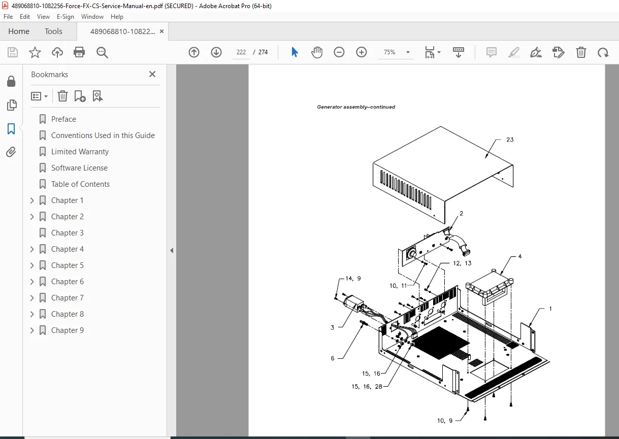
- Generator Assembly
- Exploded view diagram
- Parts List with part numbers:
- Cover and base
- Mounting hardware
- Labels and overlays
- Handles
- Front Panel Assembly
- Exploded view
- Parts List:
- Front panel components
- Receptacles
- Switches
- REM module
- Hardware
- Control Board Components
- Board-level components
- Part numbers
- Replacement notes
- Display Board Components
- LEDs (seven-segment and indicator)
- Drivers
- Connectors
- Footswitch Board Components
- Complete component list
- Part numbers
- Power Supply/RF Board Assembly
- Exploded view diagram
- Parts List:
- Heat sinks
- MOSFETs
- Diodes
- Transformers
- Capacitors
- Other components
- Supply/RF Board Components
- Detailed component list
- Part numbers and descriptions
- Critical component specifications
🔧 CRITICAL SERVICE FEATURES
✅ Instant Response™ Technology – Proprietary real-time power control
✅ 274 Pages Comprehensive Coverage – Complete service documentation
✅ REM Contact Quality Monitoring – Patient safety system diagnostics
✅ Complete Calibration Procedures – All adjustments documented
✅ RS-232 Diagnostic Interface – Advanced troubleshooting capability
✅ Component-Level Repair – Heat sink and board-level procedures
✅ Output Waveform Analysis – All modes characterized
✅ Safety Testing Protocols – IEC 60601-1 compliance verification
✅ Troubleshooting Flowcharts – Systematic diagnostic approach
✅ Complete Parts Lists – Part numbers and exploded views
📄 FILE DETAILS
| Specification | Details |
|---|---|
| Manual Title | Force FX Electrosurgical Generator CS Service Manual |
| Equipment Type | Isolated Output RF Electrosurgical Generator |
| Manufacturer | Covidien (now Medtronic) |
| Models Covered | Force FX Electrosurgical Generator CS (110V~/230V~) |
| Manual Part | Part 1 of 2 (Service Manual Text) |
| Total Pages | 274 pages |
| File Format | PDF (searchable and printable) |
| PDF Quality | ⭐⭐⭐⭐⭐ Excellent – Factory service manual quality |
| Language | English |
| Standards | IEC 60601-1, IEC 60601-2-2, IEC 60601-1-2, EU Directive 93/42/EEC |
⚡ COMPATIBLE EQUIPMENT
Generator Models:
- Covidien Force FX Electrosurgical Generator CS
- 110V~ Nominal (North America)
- 230V~ Nominal (International)
- Auto voltage selection
Compatible Accessories:
- Bipolar forceps and instruments
- Monopolar active electrodes
- REM patient return electrodes
- Handswitch instruments
- Footswitches (monopolar and bipolar)
- CUSA EXcel™ system with CEM™ nosecone
- Valleylab™ Argon Gas Delivery Unit II
Surgical Applications:
- General surgery
- Gynecological surgery
- Urological surgery
- Neurosurgery
- Cardiovascular surgery
- Orthopedic surgery
- ENT surgery
- Plastic surgery
💡 WHO NEEDS THIS MANUAL?
- Biomedical Equipment Technicians (BMETs) – Hospital clinical engineering
- Electrosurgical Equipment Specialists – Dedicated RF generator service
- Clinical Engineers – Healthcare facility technical departments
- Covidien/Medtronic Authorized Service Centers – Official repair support
- Medical Equipment Service Companies – Independent service providers
- Hospital Maintenance Departments – In-house repair capabilities
- Operating Room Equipment Managers – OR technical staff
- Surgical Equipment Distributors – Service departments
🎯 WHY THIS MANUAL IS ESSENTIAL
Life-Critical Surgical Equipment: Electrosurgical generators are essential tools in virtually all surgical procedures. Proper maintenance, calibration, and safety testing are crucial for patient safety and surgical success.
Factory Service Documentation: Official Covidien technical manual providing accurate procedures, specifications, and safety protocols required for proper service of this sophisticated RF generator.
Instant Response™ Technology: Understanding and servicing Covidien’s proprietary Instant Response technology requires factory documentation – this manual provides complete technical details of the real-time impedance sensing and power adjustment algorithms.
Complex RF Power Electronics: The Force FX combines high-voltage switching power supplies, RF amplifiers, microcontroller control, and safety monitoring systems. Service requires specialized knowledge documented in this manual.
Safety Testing Requirements: IEC 60601-1 and IEC 60601-2-2 electrical safety testing is mandatory after any repair. This manual provides complete leakage current testing and verification procedures.
Calibration Expertise: The generator requires precise calibration of current sensing, voltage sensing, reactance measurement, and energy conservation factors. This manual provides step-by-step calibration procedures.
REM System Service: The REM Contact Quality Monitoring system is a critical patient safety feature. This manual documents complete diagnostic and repair procedures.
Minimize Downtime: In surgical environments, equipment failure can halt procedures and impact patient care. This manual enables rapid diagnosis and repair.
Cost Savings: Develop in-house service capabilities to avoid expensive manufacturer service contracts and reduce equipment downtime.
Regulatory Compliance: Proper documentation and testing procedures ensure compliance with medical device regulations and hospital accreditation standards.
⚙️ TECHNICAL HIGHLIGHTS
Power Output:
- Bipolar: Up to 70W (Precise, Standard, Macro modes)
- Monopolar Cut: Various ranges by mode
- Monopolar Coag: Various ranges by mode
- CEM mode support
RF Characteristics:
- Isolated output design
- Multiple waveform types
- Frequency range optimization
- Crest factor control
Safety Systems:
- REM Contact Quality Monitoring
- IsoBloc isolation verification
- Thermal shutdown protection
- Dual microcontroller safety
- T_ON ASIC verification
Power Supply:
- Input: 110V~/230V~ (auto selected)
- Frequency: 50/60 Hz
- Type CF (Defibrillator-Proof)
- Class I equipment
Control:
- Dual microcontroller architecture
- Instant Response algorithm
- Dosage error monitoring
- RS-232 diagnostics
⚡ INSTANT DOWNLOAD – SERVICE SUPPORT IMMEDIATELY!
Stop searching for incomplete technical information when servicing Covidien Force FX electrosurgical generators! This comprehensive 274-page factory service manual gives you complete technical documentation for the Force FX CS with Instant Response™ technology. From understanding proprietary RF waveform generation to calibrating current/voltage sensing circuits, from REM contact quality monitoring diagnostics to heat sink component replacement, from IEC 60601-1 safety testing to RS-232 diagnostic commands – everything you need is here. Whether you’re a hospital biomedical technician, clinical engineer, or authorized service professional, this manual provides factory-level expertise for maintaining these critical surgical RF systems. Download instantly and have professional service capabilities for this advanced electrosurgical generator!
Pricing Rationale:
- Comprehensive 274-page service manual
- Critical surgical equipment ($20,000-$40,000+ systems)
- Proprietary Instant Response™ technology documentation
- Complete calibration procedures (current, voltage, reactance, ECON factors)
- REM safety system diagnostics and repair
- Component-level repair procedures (heat sinks, boards)
- RS-232 diagnostic interface documentation
- IEC 60601-1 safety testing protocols
- Complete parts lists with numbers
- Essential for surgical equipment service
- Covidien/Medtronic factory documentation
- Saves thousands in service contract costs