Crown CE 4000 Power Amplifier Service Repair Manual Troubleshooting Guide PDF
Original price was: $85.00.$26.95Current price is: $26.95.
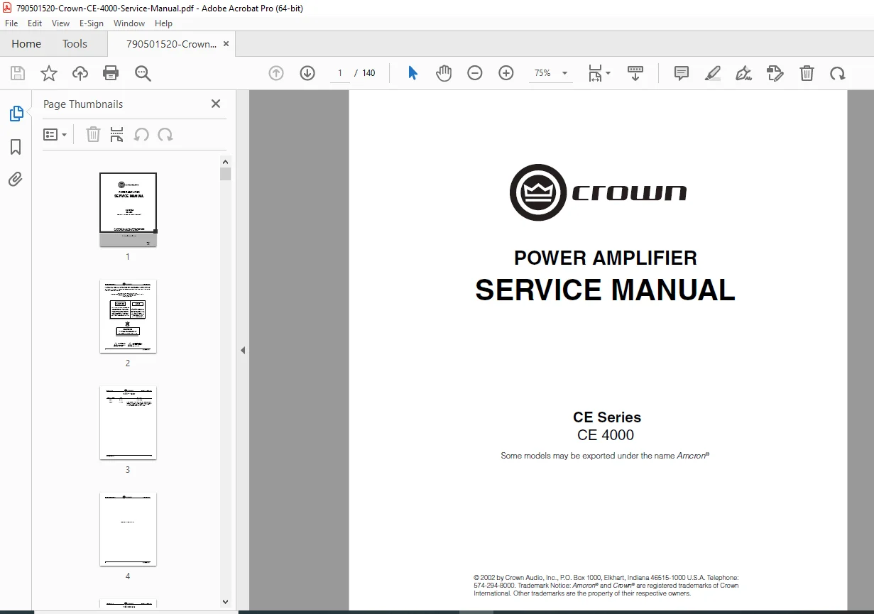
Complete Crown CE 4000 professional power amplifier service manual covering theory of operation, troubleshooting, maintenance procedures, and technical specifications. Features BCA technology details, switch-mode power supply diagnostics, modulator repair procedures, and comprehensive schematics. Essential technical documentation for certified technicians servicing Crown CE 4000 amplifiers used in professional audio installations, concert touring systems, and fixed installations worldwide.
Description
Crown CE 4000 Power Amplifier Service Repair Manual Troubleshooting Guide PDF DOWNLOAD
DESCRIPTION
This Crown CE 4000 Service Manual is the definitive technical reference for professional audio technicians maintaining and repairing Crown’s flagship CE 4000 power amplifier. This comprehensive 140-page service documentation provides complete theory of operation, detailed troubleshooting flowcharts, and precise calibration procedures essential for proper CE 4000 amplifier maintenance.
Manual Coverage & Technical Specifications
This Crown CE 4000 power amplifier service manual documents the complete amplifier system featuring Crown’s patented BCA (Balanced Current Amplifier) technology delivering high-power audio amplification from 20 Hz to 20 kHz with minimal distortion. The CE 4000 provides professional-grade power output through switch-mode power supply with power factor correction, allowing worldwide operation without voltage selector switches.
Key Technical Features Documented:
- Audio Power Output: Detailed specifications for maximum power delivery at various impedances (2Ω, 4Ω, 8Ω configurations)
- Frequency Response: ±0.25 dB from 20 Hz to 20 kHz
- THD Performance: 0.5% or less at rated 1-kHz power
- Signal-to-Noise Ratio: Better than 100 dB below rated power (A-weighted, 20 Hz to 20 kHz)
- Input Sensitivity: Three selectable options – 0.775V, 1.4V, or fixed 26dB gain
- Input Impedance: 20kΩ balanced / 10kΩ unbalanced
- Cooling System: Three-speed proportional fan control
- Physical Dimensions: EIA 19-inch rack mount, 5.25″ height × 16.25″ depth
- Weight: Net 33.3 lbs (15.1 kg)
Complete Theory of Operation
Audio Signal Path Documentation
- Input Stage Analysis: Balanced XLR/phone jack configuration with RFI protection, variable gain stage, and full-time compressor circuit operation
- Error Amplifier Circuit: Detailed mixing of output voltage and current feedback for optimal performance control
- Modulator Technology: High-speed differential comparator operation (U101/U103) with 250 kHz PWM pulse width modulation
- Triangle Generator: 250 kHz waveform generation from 4MHz clock with overlap/underlap adjustment procedures
- BCA Output Stage: Complete explanation of balanced current amplifier operation including MOSFET gate drivers, floating supply generation, and synchronized switching
- Output Filter Network: Three-stage filtering (250 kHz / 500 kHz / 250 kHz) for elimination of switching frequencies
Protection & Control Systems
- Current Monitor Circuit: Output current sensing via transformer T100 for feedback and limiting
- Current Limiter Operation: Automatic protection preventing excessive output current through comparator network
- Display Circuitry: Signal detection, clip indication, fault LED, and enable LED operation
- Thermal Management: NTC temperature sensors on heatsinks and power transformer with TLC (Thermal Limit Control) power reduction
- DC Protection: Window detector circuit with latching fault protection
- Fan Control: Three-speed automatic fan control based on temperature monitoring
Power Supply Architecture
- Power Entry & EMI Filtering: Line filtering and safety compliance documentation
- Flyback Low-Voltage Supply: Self-starting buck converter operation at 80 kHz (synchronized to 125 kHz)
- PFC Boost Stage: Power factor correction circuitry analysis
- Bridge Isolation Stage: High-voltage DC-DC converter operation
- Turn-On Control: Sequenced power-up with PTC inrush limiting and relay bypass
Comprehensive Maintenance Procedures
Disassembly Instructions
- Top Cover Removal: Step-by-step procedure for safe chassis access
- Power Supply Discharge: Critical safety procedure for capacitor discharge before servicing
- Component Removal Procedures:
- Flyback Supply PWA removal
- SST Input Module removal
- Output Panel removal
- Back Panel Assembly removal
- Line Filter PWA removal
- BFG (Bridge/Fault/Gain) PWA removal
- Main PWA removal
Advanced Troubleshooting Guides
- Flyback Power Supply Troubleshooting: Complete diagnostic flowchart for low-voltage supply failures
- Triangle Wave Generator Diagnostics: BCA output stage testing procedures
- Power Supply, PFC & Bridge Converter Testing: High-voltage section troubleshooting
- Symptom Identification: Systematic approach to fault diagnosis
- Cause Identification & Repair: Root cause analysis and repair procedures
Electrical Checkout Procedures
- Quiescent AC Power Draw Test: Verification of proper idle current consumption
- Gain Switch Verification: Testing all three input sensitivity settings (0.775V, 1.4V, 26dB)
- Bridge-Mono Operation Test: Proper configuration verification
- Frequency Response Measurement: ±0.25 dB flatness verification
- Short Circuit Protection Test: Output protection verification
- Output Power Testing: Maximum power delivery confirmation at various impedances
- Intermodulation Distortion (IMD): Audio quality verification
- Signal-to-Noise Ratio Testing: Background noise measurement
- Crosstalk at 20 kHz: Channel separation verification
- Post-Test Configuration: Proper settings restoration
Precision Calibration Procedures
- Gaussian Filter Calibration: 7th-order 32 kHz low-pass filter adjustment for flat frequency response
- Overlap Correction & Adjustment: Critical BCA output stage timing calibration
- Current Sensing Calibration: Accurate current limiting threshold setting
- Output Filter Calibration: Final stage filter optimization
Complete Parts Documentation
Mechanical Parts Listings
- CE 4000 main amplifier assembly exploded views
- Back panel assembly components
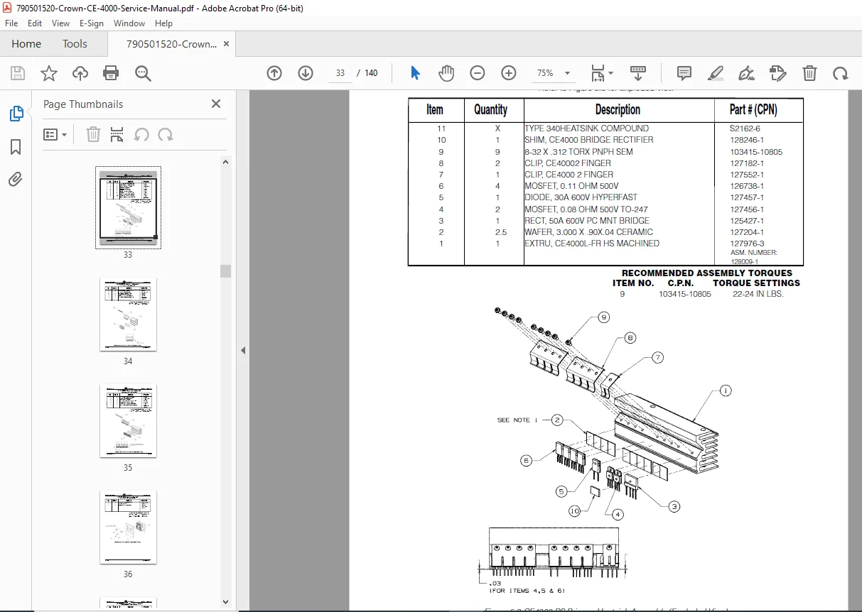
- Primary heatsink assembly parts
- Diode heatsink assembly components
- Output heatsink assembly parts
- Standard input assembly (SST module)
- Standard domestic output assembly configurations
- Power switch assembly components
Circuit Board Parts
- Detailed parts lists for all printed wiring assemblies (PWAs)
- Main PWA component listings with reference designators
- Flyback supply PWA parts
- BFG (Bridge/Fault/Gain) PWA components
- Line filter PWA parts
- Cross-reference between circuit board and schematic part numbers
- Proper part substitution guidelines
- Critical safety-rated component identification
Comprehensive Schematic Documentation
Complete schematic diagrams included for:
- Audio signal path and modulator circuits
- BCA output stage and gate drive circuits
- Protection and control circuitry
- Display and indicator circuits
- Power supply (flyback, PFC, bridge converter)
- Input module (SST) schematics
- Output connector configurations
- EMI filter circuits
Surface Mount Technology Service Information
Specialized guidance for servicing SMT components including proper tools, techniques, and precautions for repairing modern surface-mount printed circuit boards found throughout the CE 4000 amplifier.
Required Test Equipment Specifications
Complete listing of test equipment needed for proper CE 4000 service:
- AC power analyzer
- Audio oscillator with low distortion
- Audio spectrum analyzer
- Distortion meter (THD+N)
- Differential oscilloscope probes
- Isolation transformer
- Load resistors (various impedances)
- RMS voltmeter
- Frequency counter
Safety Information & Warnings
CRITICAL SERVICE WARNINGS:
- High-voltage warnings for switch-mode power supply sections
- Proper discharge procedures for energy storage capacitors
- Isolation transformer requirements for primary side measurements
- Safety-rated component replacement requirements
- Electrical shock prevention procedures
- Proper grounding techniques
Applications & Compatible Systems
This service manual covers CE 4000 amplifiers used in:
- Professional concert touring systems
- Fixed installation audio systems
- Houses of worship sound reinforcement
- Theater and performing arts venues
- Stadium and arena audio systems
- Recording studio monitor systems
- Broadcast facilities
- Conference and convention centers
The CE 4000 features SST (System Solution Topologies) module compatibility allowing custom input configurations for various professional audio system requirements.
FILE DETAILS
| Manual Attribute | Specification |
|---|---|
| Manual Name | Crown CE 4000 Power Amplifier Service Manual |
| Model Covered | Crown CE 4000 (all variants including Amcron® export versions) |
| Publication Date | November 2002 (Revision B) |
| Manual Number | 130485-1 Rev. B |
| Total Pages | 140 pages |
| PDF Quality | Excellent – Original factory scanned service documentation with clear text and diagrams |
| File Size | 6.76 MB |
| Language | English with French safety warnings |
| Document Type | Official Crown Factory Service Manual |