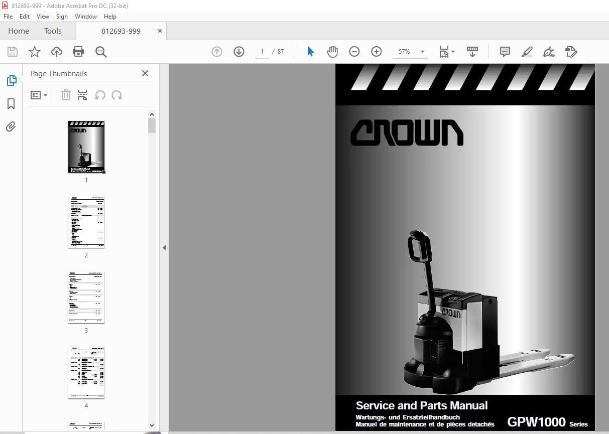
Crown Forklift GPW1000 Series Service & Parts Manual PDF
$18.95
Crown Forklift GPW1000 Series Service & Parts Manual – PDF DOWNLOAD
Description
Crown Forklift GPW1000 Series Service & Parts Manual – PDF DOWNLOAD
FILE DETAILS:
Crown Forklift GPW1000 Series Service & Parts Manual – PDF DOWNLOAD
Language : Eng,GR,FR
Pages :87
Downloadable : Yes
File Type : PDF
TABLE OF CONTENTS:
Crown Forklift GPW1000 Series Service & Parts Manual – PDF DOWNLOAD
SECTION M 1 LUBRICATION AND ADJUSTMENT
Lubrication and Adjustments M1 -1710-001
Lubricant and oil recommendation M1.1 -1710-001
Check and maintenance plan M1.2 -1710-001
– 8 hour maintenance plan
– 100 hour maintenance plan
– 250/500 hour maintenance plan
– 1000/2000 hour maintenance plan
Lubrication points M1.3 -1710-010
SECTION M 4 ELECTRICAL MAINTENANCE
Switch definition M4 -1710-001
General diagram of electronic parts M4.1 -1710-001
Working with circuit diagram M4.2 -1710-001
– Wiring colour code
– Colour code according to DIN 47100
– Table of abbreviations
– Electronic circuit symbols
MOSFET Transistor Control M4.3 -1710-001
– Characteristics
– Details of functions
– Pilot wire pins
– Power cable pins
– Operation field
– Diagnosis with LED status
– Maintenance of impulse control
– Cleanin
– Removal and installation of impulse control
– Examining impulse control
– Investigating malfunctioning (see table)
– Fault recovery
Programme M4.4 -1710-001
– General
– Installation
– Keys
– Display
– Scroll Display arrow key
– Change Value arrow key
– More Info key
Operating Menu M4.4 -1710-005
– Programme ke
– Test key
– Copy programme
– Special diagnosis menu
– Deletion of old diagnosis
– Allowing for error in programming
– Self testing programming equipment
– Menu programming equipment (table)
DESCRIPTION PAGE ID NUMBER
– Test menu (table)
– Diagnosis menu and special programme menu
– Special programme menu
– Curtis Controller Adjustments
SECTION M 5 BRAKE MAINTENANCE
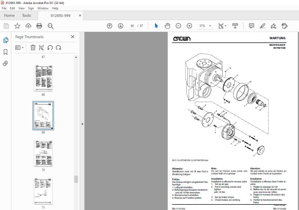
Brake M5 -1710-001
– General
– Removal
– Installation
– Setting of air gap
– Setting of brake torque
– Execution of brake test
SECTION M 7 MAST- / LIFT STRUCTURE MAINTENANCE
Tensionbars M7 -1710-001
– Setting of tensionbars
– Setting of fork height
WIRING DIAGRAMS
Wiring diagram DIA -1710-001
Power cable wiring
HARNESSES
Wiring harness KLB -1710-001
– Main wiring harness
– Tillerarm wiring harness
– Tillerarm wiring harness F/C
– Tillerarm wiring harness
– ORS/BRS/BR wiring harness
– ORS/BRS/BR wiring harness F/C
HYDRAULIC SCHEMATICS
Hydraulic Schematic HYD -1710-001
TOOLING / CONNECTORS
Special tooling / Plug connector WZ -1710-001
8/96
GPW INDEX
IDX – 1710 – 003 IDX – 1710 – 003
Printed in Germany
DESCRIPTION PAGE ID NUMBER
SECTION 1 POWER UNIT PARTS / COVERS
Power Unit 1 -1710- 02
Caster Assembly 1.5 -1710- 02
SECTION 2 HYDRAULIC PARTS
Pump and Motor 2.9 -1710- 02
SECTION 3 DRIVE UNIT PARTS
Drive Unit 3 -1710- 02
Drive Motor 3.3 -1710- 02
SECTION 4 ELECTRICAL PARTS
Contactor Panel 4.1 -1710- 02
Driver Board 4.3 -1710- 02
Drive Contactor 4.4 -1710- 02
Control Handle 4.5 -1710- 08
Control Handle Freazor Corrosion 4.5 -1710- 58
Battery Charger 4.8 -1710- 02
Battery 4.8 -1710- 04
SECTION 5 BRAKE PARTS
Brake System 5.0 -1710- 04
Brake 5.0 -1710- 02
SECTION 7 MAST- / LIFT STRUCSTURE PARTS
Lift Structure 7.7 -1710- 02
Load Backrest 7.9 -1710- 02
SECTION 8 CYLINDER PARTS
Lift Cylinder 8.0 -1710- 02
SECTION 10 MISCELLANEOUIS SERVICE INFORMATION
Labels and Decals 10.9-1710- 02
8/96
GPW RESUM
IDX – 1710 – 001 IDX – 1710 – 001
Printed in Germany
DESCRIPTION PAGE ID NUMBER
Instructions générales d’entretien MA -1710-001
Section M 1 LUBRIFICATION ET REGLAGE
Lubrification et calibrage M1 -1710-001
Conseil pour lubrifiant et huile M1.1 -1710-001
Programme de test et d’entretien M1.2 -1710-001
– Programme d’entretien et test de
8 heures.
– Programme d’entretien et test de
100 heures.
– Programme d’entretien et test de
250 à 500 heures.
– Programme d’entretien et test de
1000 à 2000 heures.
Point de lubrification M1.3 -1710-010
Section M 4 INSTALLATIONS ELECTRIQUE/EQUIPEMENT
Définition des commandes M4 -1710-001
Schéma général des parties électroniques M4.1 -1710-001
Utiliser un schéma de circuit M4.2 -1710-001
– Code de couleur des câbles
– Code des couleurs selon DIN 47100
– Tableau des abrévations
– Symboles des circuits électriques
Contrôle à impulsion M4.3 -1710-001
– Caractéristiques
– Détails des fonctions
– Connecteur principal
– Connection des câbles de
transmission
– Domaine d’utilisation
– Diagnostic avec la position LED
– Entretien du contrôle à impulsion
– Purification
– Montage et démontage du contrôle à
impulsion
– Test du contrôle à impulsion
– Detection d’erreurs (voir tableau)
– Effacement défauts
Système de programmation M4.4 -1710-001
– Généralités
– Installation
– Touches
– Affichage
– Touche „flèche“ pour faire défiler
l’écran
– Touche „flèche“ pour modifier une
valeur
– Touche d’information
8/96
GPW RESUM
IDX – 1710 – 002 IDX – 1710 – 002
Printed in Germany
DESCRIPTION PAGE ID NUMBER
Menu d’utilisation M4.4 -1710-005
– Touche de programmation
– Touche de test
– Programme de copie
– Menu pour diagnostics spéciaux
– Annulation des diagnostics antérieurs
– Marge de tolérance dans la
programmation
– Auto-test du système de
programmation
– Système de programmation du menu
(tableau)
– Menu des tests (tableau)
– Menu des diagnostics et menu des
programmes speciaux
– Menu de programme spécial
– Curtis Controller Einstellungen
Section M 5 FREIN
Freins M5 -1710-001
– Généralités
– Démontage
– Montage
– Réglage du jeu (entre fers)
– Réglage du couple de serrage du frein
– Execution de tests de freinage
SECTION M 7 BARRES DE LEVAGE
Barres de levage M7 -1710-001
DESCRIPTION PAGE ID NUMBER
SYSTEME HYDRAULIQUE
Plan du système hydraulique HYD-1710-001
OUTILS SPECIAUX/BORNE DE CONNECTION
Outils spéciaux/Borne de connection WZ -1710-001
SECTION 1 PIÈCES GROUPE DE TRANSMISSION
Groupe de transmission 1 -1710- 02
Groupe roue d’appui 1.5 -1710- 02
SECTION 2 PIECES HYDRAULIQUES
Pompe et moteur 2.9 -1710- 02
SECTION 3 PIECES GROUPE DE TRACTION
Organes supérieurs de direction 3 -1710- 02
Moteur de traction 3.3 -1710- 02
SECTION 4 PIECES ELECTRIQUES
Panneau de contacteur 4.1 -1710- 02
Carte pilote 4.3 -1710- 02
Contacteur 4.4 -1710- 02
Direction 4.5 -1710- 08
Direction FC 4.5 -1710- 58
Connecteur 4.8 -1710- 02
Batterie 4.8 -1710- 04
SECTION 5 PIECES FREINS
Groupe frein 5.0 -1710- 04
Frein 5.0 -1710- 02
SECTION 7 PIECES DE LEVAGE
Dispositif de levage 7.7 -1710- 02
Butée de charge 7.9 -1710- 02
SECTION 8 PIECES DE CYLINDRE
Cylindre 8.0 -1710- 02
SECTION 10 AUTRES INFORMATIONS
Autocollants et étiquettes
IMAGES PREVIEW OF THE MANUAL:
S.M 5/24