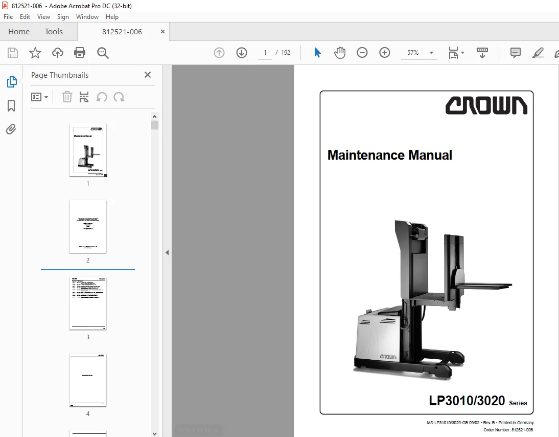
Crown Forklift LP3010/3020 Series Maintenance Manual – PDF DOWNLOAD
$24.95
Crown Forklift LP3010/3020 Series Maintenance Manual – PDF DOWNLOAD
Description
Crown Forklift LP3010/3020 Series Maintenance Manual – PDF DOWNLOAD
FILE DETAILS:
Crown Forklift LP3010/3020 Series Maintenance Manual – PDF DOWNLOAD
Language : English
Pages :192
Downloadable : Yes
File Type : PDF
TABLE OF CONTENTS:
Crown Forklift LP3010/3020 Series Maintenance Manual – PDF DOWNLOAD
ITD – INTRODUCTION PAGE SER-NR CUT REV
Safety Symbols used in the Manual 3 Rev1 04/00
General Maintenance and Repair Safety Notes 3
Maintenance and Repair 3 Rev1 04/00
Before Leaving the Truck 4
Before Carrying out Work on the Truck 4
Before Operating the Truck 4
Warnings and Labels on the Truck 4
General 7
Operating Instructions 7
Service Training 7
Ordering Spare Parts 7
Using the Manual 7
Model-Number 8
M1 – LUBRICATION AND ADJUSTMENT PAGE SER-NR CUT REV
Jacking up the Truck 11
Lifting the Vehicle with a Crane 12
Lifting the Vehicle with a Fork-Lift Truck 12
Towing the vehicle away 12
Access to Components 13
LP3010 Overview 13
LP3020 Overview 14
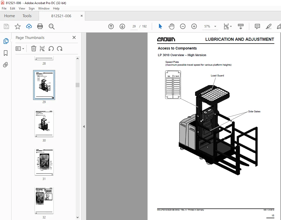
LP 3010 Overview – High Version 15
Access to Components 17
Access to Drive Unit, Hydraulic
System and Electrical Components 18
Maintenance 19
Operator Involvement 19
Daily Maintenance Record 19
Inspection and Maintenance
Schedule 19
Scheduled Replacement of High Pressure Hoses 22
Monthly or Every 100 Operating Hours 23
Every 3 Months or 250 Operating Hours 25
Every 6 Months or 500 Operating Hours 27
Annually or Every 1,000 Operating Hours 29
Recommended Lubricants 31
Lubrication Points, Overview 33
Torques 34
M2 – HYDRAULICS PAGE SER-NR CUT REV
Changing Hydraulic Oil 37
Hydraulic Pipes and Accessories 37
Removing the Hydraulic Unit 38
Replacing the Hydraulic Pump 39
Removal 39
Installation 39
Commissioning 39
Pump Motor 40
Replacing the Hydraulic Filter 40
Oil Change 41
Valve Block 42
Pressure Relief Valves 42
Operation 42
M2 – HYDRAULICS PAGE SER-NR CUT REV
Platform Lift Pressure Relief Valve Setting 42
Aux Lift Pressure Relief Valve Setting 43
Non-Return Valve 43
Functional Test: 43
Compensation Valve 43
Functional Test: 43
Line Break Safety Device 44
Tools Required: 44
Line Break Safety Device Functional Test 44
Emergency Lowering Valve 45
Tools Required: 45
Emergency Lowering Valve Functional Test 45
M3 – DRIVE UNIT PAGE SER-NR CUT REV
Drive Unit 49
Preparation 49
Drive Unit Removal 49
Gear Unit Repair 51
General 51
Drive Unit Removal 51
Gear Unit Assembly 53
Installing the Drive Unit 54
M4 – ELECTRICS PAGE SER-NR CUT REV
Electrical Components 57
AV
Alarm 57
CX
Horn 57
F1, F2, FA,FA4
Fuses 57
F3, FA3
Fuses 57
Aisle Recognition Sensor 57
Aisle Recognition Sensor 57
Brake 57
HN3
Alarm 57
Travel Direction Contactors 57
Main Contactor 57
Steering Contactor 58
Traction Motor 58
Pump Motor 58
Steering Motor 58
Chain Slack Switch 58
Steering Limit Switch 58
TABLE OF CONTENT
MS-LP3010/3020-GB 09/02 • Rev A • Printed in Germany
M4 – ELECTRICS PAGE SER-NR CUT REV
MFC
Lift Limit Switch (Cabin) 58
MFF
Lift Limit Switch (Forks) 58
Overhead Guard Monitor 58
Lift Interruption Switch 58
MMI,MMA,PT
Transmitter 58
Door Switch 59
MP1,MP3
Pallet Recognition Switch 59
MR
Lower Brake Switch 59
MS1, MS2
Steering: Tachogenerator 59
MSC,MDC,PTP
Cabin Lift / Lower 59
MV2, MV3
Lift Height Dependent Speed Reduction 59
PE
Emergency Disconnect Switch 59
PCE, PCEglf
Brake Switch 60
PCS, PCD
Fork Lift/Lower 60
PCS, PCSD, MCS
Dead Man Switch 60
Aisle Guidance Two-Hand Switch 60
PCX, PCXglf
Horn Switch 60
PEA
Chain Slack Bypass Switch 60
Work Lights Switch 60
Bypass Switch 60
Pressure Switch 60
Steering Angle Potentiometer 61
Key Switch 61
Trip Relay 61
MK3N Traction Controller 62
General 62
Precautionary Measures 62
Maintenance 62
Replacing the Traction Controller 62
Settings after Replacing the Traction
Controller 63
MS-LP3010/3020-GB 09/02 • Rev A • Printed in Germany
M4 – ELECTRICS PAGE SER-NR CUT REV
MK3N Lift Controller 64
General 64
Precautionary Measures 64
Maintenance 64
Replacing the Lift Controller 64
Settings after Replacing the Lift Controller 65
EPS-DC Steering Controller 66
General 66
Precautionary Measures 66
Maintenance 66
Replacing the Traction Controller 66
Settings after Replacing the Steering Controller 67
Replacing Fuses 67
Graphic Display 68
General 68
Precautionary Measures 68
Maintenance 68
Replacing the Graphic Display 69
Settings after Replacing the Graphic Display 69
Programmer 71
General 71
Connecting the programmer and the adapter 72
Data Connection to the Pump Controller: 72
Data connection to the Traction Controller: 72
Data Connection to the Graphical Display 73
Operating Menu 74
General 74
Menu Functions 74
Graphic Display, Menu Structure 75
Graphic Display; Parameter Change Menu 76
Maximum Speed Setting 77
Graphic Display
TESTER Menu 78 Rev 1 09/02
Graphic Display
SAVE PARAMETER Menu 79
Graphic Display
ALARMS Menu 80
Graphic Display
Language Reference List for the ALARM Menu 84
Graphic Display
SET OPTIONS Menu 85
Graphic Display
ADJUSTMENTS Menu 86
Traction Control System, Menu Structure 87
Traction Control System, PARAMETER CHANGE Menu 88
Traction Control System,
TESTER Menu 89
Traction Control System,
ALARMS Menu 90
Traction Control System,
SET MODEL Menu 91
Lift Control System, Menu Structure 92
Lift Control System,
PARAMETER CHANGE Menu 93
Lift Control System,
TESTER Menu 94
Lift Control System,
ALARMS Menu 95
VII
TABLE OF CONTENT
MS-LP3010/3020-GB 09/02 • Rev A • Printed in Germany
M4 – ELECTRICS PAGE SER-NR CUT REV
Steering Control System, Menu Structure 96 Rev 1 09/02
Steering Control System,
PARAMETER CHANGE Menu 97
Steering Control System,
TESTER menu 98
Steering Control System,
SET OPTIONS menu 99
Steering Control System,
ADJUSTMENTS menu 100
Steering Control System, ALARM 101
Audible Alarm 101
Programmer, ALARMS menu 101
Remote Control for Platform 102
Traction Control System Safety Test 103
Electric Motors 105
General Maintenance Instructions 105
Preparation 105
Important Maintenance Instructions 105
Drive Motor Maintenance 106
Access to Brushes 106
Maintenance 106
Armature 106
Bearings 106
Pump Motor Maintenance 107
Access to Brushes 107
Maintenance 107
Armature 107
Bearings 107
Steering Motor Maintenance 108
Access to Brushes 108
Maintenance 108
Battery 109
General 109
Operation 109
Replacing the Battery 109
M-5 – BRAKE PAGE SER-NR CUT REV
General Functional Description 113
Removal 113 Rev 1 09/02
Assembly 114 Rev 1 09/02
Air Gap Setting 114 Rev 1 09/02
Brake Moment Setting 114 Rev 1 09/02
Brake Test 114 Rev 1 09/02
M6 – STEERING PAGE SER-NR CUT REV
Steering 119
Operation 119
Steering Chain Adjustment 119
Steering Pod Removal / Installation 120
Steering Motor Removal / Assembly 120
Steering Transmission
Removal / Assembly 121
Potentiometer (PTR) Installation 122
Functional Test 122
Steering Limit Switch (MF) 122
Replacing the Steering Limit Switches 122
Limit Switch Test 123
Limit Switch Adjustment 123
VIII
TABLE OF CONTENT
MS-LP3010/3020-GB 09/02 • Rev A • Printed in Germany
M7 – LIFTING MECHANISM PAGE SER-NR CUT REV
Torques 127
Fork Settings 127
Mast Control
(Fitted) 127
Flaking 127
Mast Stop Buffer 127
Fork Carriage Stop Screws 127
Removing the Platform without Aux Lift
(1200 mm lift height) 128
Removing the Platform with Aux Lift
(1200 mm lift height) 130
Removing Platform without Aux Lift
(1800 mm lift height) 133
Removing Platform with Aux Lift
(1800 mm lift height) 136
Mast Rollers 139
Removing the Mast Rollers 139
Fitting the Mast Rollers 139
Guide Rollers 139
Guide Roller Removal 139
Guide Roller Installation 140
Platform Installation (all variants) 141
Fork Carriage (Aux Lift Only) 142
Fork Carriage Removal 142
Removing the Fork Carriage Rollers 143
Fork Carriage Roller Installation 143
Fork Carriage Installation 144
Tensioning the Lift Chain 144
Lift Chains 146
General 146
INSPECTION 146
Cleaning 146
Wear 146
Chain Dimensions: 146
Freedom of Movement 147
Chain Anchor and Pulleys 147
Worn or Missing Plates 147
Protruding or Turned Chain Pins 147
Corrosion 148
Chain Lateral Wear 148
Misalignment of Lift Components 148
LIFT CHAIN LUBRICATION 149
Fork Tine Test 150
General 150
Fork Identification 150
Repairs 150
Crack Inspection 150
Fork Blade Warping 151
Verticality Test 151
Measuring the Fork Tip Width 152
Fork Tine Height Difference 152
Fork Stop 152
Wear 153
IX
TABLE OF CONTENT
MS-LP3010/3020-GB 09/02 • Rev A • Printed in Germany
M8 – CYLINDERS PAGE SER-NR CUT REV
Cylinders 157
General 157
Plunger Cylinders (single-acting) 157
Piston Cylinder (Double-Acting Cylinder) 158
Maintenance 160
Inspection 160
Seal Installation 161
General 161
Aux Lift Cylinder 161
Removal – Preparation 161
Aux Lift Cylinder Removal 161
Repairing the Aux Lift Cylinder 162
Disassembly 162
Inspection 162
Assembly 163
Aux Lift Cylinder Assembly 163
Lift Cylinder 163
Removal – Preparation 163
Lift Cylinder Removal 164
Repairing the Lift Cylinder 164
Disassembly 164
Inspection 165
Lift Cylinder Assembly 165
DIA – ELECTRICAL DIAGRAMS PAGE SER-NR CUT REV
Electrical Circuit 169
HYD – HYDRAULIC SCHEMATIC PAGE SER-NR CUT REV
Hydraulic System 173
Operation 173 Rev 2 09/02
HLP3010,
1025 mm lift height, without aux lift 174 Rev 2 09/02
LP3020, 1845 mm lift height,
with aux lift 175 Rev 2 09/02
LP3010, 1620 mm lift height,
without aux lift 176 Rev 2 09/02
LP3020, 2440 mm lift height,
with aux lift 177 Rev 2 09/02
IMAGES PREVIEW OF THE MANUAL:
S.M 5/24