Crown Forklift RR 5200S AC RR 5200S DC Service & Parts Manual – PDF DOWNLOAD
$33.95
Crown Forklift RR 5200S AC RR 5200S DC Service & Parts Manual – PDF DOWNLOAD
Description
Crown Forklift RR 5200S AC RR 5200S DC Service & Parts Manual – PDF DOWNLOAD
FILE DETAILS:
Crown Forklift RR 5200S AC RR 5200S DC Service & Parts Manual – PDF DOWNLOAD
Language : English
Pages :1626
Downloadable : Yes
File Type : PDF
TABLE OF CONTENTS:
Crown Forklift RR 5200S AC RR 5200S DC Service & Parts Manual – PDF DOWNLOAD
03 – 12/01 General Maintenance MA–04.0–001
04 – 10/02 Introduction ITD–1452–001
Cleaning of Material Handling Equipment MA–1140–050
02 – 10/02 Control of Hazardous Energy MA–1452–100
SECTION M1 LUBRICATION AND ADJUSTMENTS
13 – 9/02 Lubrication and Adjustment M1.0–04.0–001
Lubricant & Fluid Chart M1.0–04.0–002
Identification Chart M1.0–04.0–003
01 – 10/02 Lubrication and Adjustment M1.0–1452–500
01 – 11/02 Componentry M1.0–1452–700
03 – 11/02 Torque Values M1.9–14.0–001
SECTION M2 HYDRAULIC MAINTENANCE
01 – 10/02 Hydraulic System M2.0–1452–001
Filter M2.0–1452–002
Reservoir M2.0–1452–002
Drift Test M2.0–1452–002
02 – 11/02 Hydraulic Circuits M2.0–1452–020
03 – 1/02 Hydraulic Schematic Symbols M2.1–00.0–001
Hydraulic Pump M2.1–1452–001
01 – 10/02 Manifold M2.4–1452–001
Hydraulic Troubleshooting Chart M2.9–1452–001
SECTION M3 DRIVE UNIT MAINTENANCE
02 – 11/02 Drive Unit M3.0–1452–001
Drive Tire Replacement M3.0–1452–001
Drive Unit Lubrication System M3.0–1452–001
• Oil Pump Disassembly M3.0–1452–002
• Oil Pump Assembly M3.0–1452–002
Undercarriage Inspections and Adjustments M3.0–1452–003
Drive Unit Removal M3.0–1452–005
SECTION M4 ELECTRICAL MAINTENANCE
01 – 9/01 Electrical Wiring † M4.1–2720–001
Capacity Data Monitor M4.3–1452–200
Height Sensor M4.3–1452–300
AC Traction Drive M4.3–1452–600
01 – 9/02 ACCESS 1 2 3 (Software Version 122694-001-01) M4.3–1452–700
01 – 8/02 Event Codes (Software Version 122694-001-01) M4.3–1452–800
02 – 11/02 Contactor P2 M4.4–04.2–001
01 – 2/98 Contactor ED M4.4–7330–001
Multi Task Control M4.5–1452–500
Battery M4.6–1452–500
02 – 9/02 Motor Chart M4.7–1452–100
4021
† Denotes new form on this inde.
Printed in U.S.A.
Serial No. of Units Used For
From:
To:
Standard Special Date
Revision Title Page Number
RR RD No. – Date September 27, 2002
C RR/RD 5200S (AC) SERIES INDE
01 REV. 1/03
ID–1452–601 ID–1452–601
Crown 2002 PF13416-2 Rev. 1/03
SECTION M5 BRAKE MAINTENANCE
01 – 6/02 Brakes M5.0–1452–001
Adjustment M5.0–1452–002
Assembly M5.0–1452–004
Caster Brake M5.0–1452–006
Troubleshooting M5.0–1452–007
SECTION M6 STEERING MAINTENANCE
Steering Motor M6.2–1452–001
SECTION M7 MAST MAINTENANCE
Mast M7.0–1452–001
06 – 12/01 Lift Chain M7.5–18.0–001
Inspection M7.5–18.0–001
Lubrication M7.5–18.0–003
Replacement M7.5–18.0–004
Leaf Chain Disconnect M7.5–18.0–005
01 – 1/00 Fork Inspection M7.8–04.2–001
SECTION M8 CYLINDER MAINTENANCE
02 – 11/02 Cylinder Lift M8.0–1452–001
Removal M8.0–1452–001
Disassembly M8.0–1452–005
Seal Removal M8.0–1452–006
Seal Installation M8.0–1452–007
Assembly M8.0–1452–008
Bleeding M8.0–1452–009
Cylinder Tilt M8.6–1452–001
Disassembly M8.6–1452–001
Rod Disassembly M8.6–1452–002
Seal Replacement M8.6–1452–002
Assembly M8.6–1452–002
SECTION M9 REACH ASSEMBLY MAINTENANCE
Reach Mechanism M9.0–1452–001
Cylinder Adjustment M9.0–1452–001
Disassembly M9.0–1452–002
Bushing Replacement M9.0–1452–003
Center Pivot Repair/Adjustment M9.0–1452–004
Reassembly M9.0–1452–004
Cylinder Flushing and Bleeding Procedures M9.0–1452–005
Reach Assembly M9.0–1652–001
Cylinder Adjustment M9.0–1652–001
Disassembly M9.0–1652–002
Bushing Replacement M9.0–1652–004
Center Pivot Repair/Adjustment M9.0–1652–004
Reassembly M9.0–1652–005
Printed in U.S.A.
Serial No. of Units Used For
From:
To:
Standard Special Date
Revision Title Page Number
RR RD No. – Date September 27, 2002
C RR/RD 5200S (AC) SERIES INDE
01 REV. 1/03
ID–1452–602 ID–1452–602
Crown 2002 PF13416-3 Rev. 1/03
SECTION M10 GLOSSARY
02 – 9/02 Glossary M10–1452–700
WIRING DIAGRAMS
Wiring Diagram Introduction DIA–ITD–001
03 – 9/02 Wiring Diagram Inde DIA–1452–300
01 – 9/02 Wiring Diagram Inde DIA–1452–314
HYDRAULIC SCHEMATICS
01 – 9/02 Hydraulic Schematic HYD–1452–100
SECTION 1 POWER UNIT PARTS
02 – 8/02 Floorboard 01.0–1452–050
Upper Foot Rest Area 01.0–1452–075
Undercarriage Articulation 01.0–1452–600
01 – 10/02 Power Unit 01.0–1452–700
01 – 12/02 Mast Guard 2260 mm / 89 in. Collapsed Height 01.2–1452–001
01 – 12/02 Mast Guard 2415 & 2720 mm / 95 & 107 in. Collapsed Height 01.2–1452–025
02 – 12/02 Mast Guard 3025 thru 4370 mm/119 thru 172 in. Coll. Hght. 01.2–1452–050
01 – 10/02 Overhead Guard 01.2–1452–200
Battery, Retainers, Spacers 01.2–1452–300
Seat 01.5–1452–001
SECTION 2 HYDRAULIC PARTS
01 – 10/02 Hydraulic Reservoir 02.0–1452–025
01 – 12/02 Hydraulic – Manifold 02.0–1452–075
Steering Control 02.0–1452–100
01 – 9/02 Mast Hydraulics 02.0–1452–400
Drive In Rack Mast Hydraulics † 02.0–1452–500
Reach Hydraulics – Tilt 02.0–1452–600
01 – 10/02 Reach Hydraulics – Tilt 02.0–1452–602
Reach Hydraulics – Tilt & Side Shift 02.0–1452–800
01 – 10/02 Reach Hydraulics – Tilt & Side Shift 02.0–1452–802
Pump – Lift 10cc Displacement 02.1–1452–500
Pump – Lift 14cc Displacement 02.1–1452–525
Pump – Lift 10cc Displacement Load Sensing 02.1–1452–600
Pump – Lift 14cc Displacement Load Sensing 02.1–1452–625
Motor – Lift 170 mm / 6.6 in. Diameter with Sensors 02.2–1452–001
Motor – Lift 170 mm / 6.6 in. Diameter 02.2–1452–050
Motor – Lift 190 mm / 7.5 in. Diameter with Sensors 02.2–1452–150
01 – 10/02 Manifold 02.4–1452–001
Manifold 02.4–1452–003
Manifolds Reach 02.4–1452–050
† Denotes new form on this inde.
Printed in U.S.A.
Serial No. of Units Used For
Standard Special Date
Revision Title Page Number
RR RD No. – Date September 27, 2002
C RR/RD 5200S (AC) SERIES INDE
01 REV. 1/03
ID–1452–603 ID–1452–603
Crown 2002 PF13416-4 Rev. 1/03
SECTION 3 DRIVE UNIT PARTS
Drive Unit 03.0–1452–001
01 – 9/02 Drive Unit Lubrication System 03.0–1452–200
02 – 9/02 Motor – Traction 03.1–1452–150
Tire 03.2–1452–001
SECTION 4 ELECTRICAL PARTS
01 – 7/02 Electrical Components 04.0–1452–600
01 – 7/02 Contactors & Fuses 04.1–1452–300
Distribution Panel 04.3–1452–100
11 – 10/02 Contactor P2 04.4–6535–050
04 – 10/02 Contactor ED 04.4–7330–050
02 – 10/02 Multi-Task Control 04.6–1452–100
Display 04.8–1452–001
01 – 9/02 Height Sensor 04.8–1452–100
02 – 12/02 Control Cable 04.8–1452–200
04 – 10/02 Connectors 04.8–1452–300
01 – 10/02 Fork Tilt Switch 04.8–1452–500
09 – 10/02 Strobe Light 04.9–10.0–550
02 – 12/02 Overhead Guard Accessories 04.9–1452–050
01 – 5/02 Freezer/Corrosion 04.9–1452–500
SECTION 5 BRAKE PARTS
01 – 10/02 Caster and Brake Assembly 05.3–1452–001
02 – 10/02 Brake – Traction Motor 05.3–1452–100
SECTION 6 STEERING PARTS
Steering System 06.0–1452–700
01 – 10/02 Steer Motor 06.2–1452–001
Steer Unit 06.3–1452–001
SECTION 7 MAST PARTS
05 – 10/02 Mast TT – 185 mm / 7.25 in. Channel 07.2–1452–100
Drive In Rack Mast † 07.2–1452–200
Removable Outrigger Ends 07.2–1452–500
Load Wheel 07.4–1452–001
Yoke 07.5–1452–250
Load Backrest 07.8–1452–001
06 – 3/01 Forks 07.9–08.0–003
SECTION 8 CYLINDER PARTS
03 – 12/02 Cylinder – Lift – TT 08.3–1452–001
Cylinder – Carriage – TT 08.3–1452–050
Cylinder – Carriage – TT 08.3–1452–052
Cylinder – Reach 08.5–1452–001
Cylinder – Tilt 08.6–1452–001
Cylinder – Side Shift 08.7–1452–050
† Denotes new form on this inde.
Printed in U.S.A.
Serial No. of Units Used For
From:
To:
Standard Special Date
Revision Title Page Number
RR RD No. – Date September 27, 2002
C RR/RD 5200S (AC) SERIES INDE
01 REV. 1/03
ID–1452–604 ID–1452–604
Crown 2002 PF13416-5 Rev. 1/03
SECTION 9 REACH MECHANISM PARTS
02 – 12/02 Reach – Tilt 09.0–1452–001
03 – 12/02 Reach – Tilt w/Sideshift 09.0–1452–100
03 – 12/02 Reach – Tilt 09.0–1652–001
03 – 12/02 Reach – Tilt & Sideshift 09.0–1652–100
SECTION 10 ACCESSORIES
04 – 1/03 Labels & Decals 10.9–1452–600
SECTION 11 MISCELLANEOUS SERVICE INFORMATION
01 – 10/02 Technical Service Bulletins – contains all service bulletins pertaining 11.0–1452–100
to this series.
01 – 10/02 Kits, Instructions – contains part numbers of various service kits 11.0–1452–200
pertaining to this series, with instructions referenced.
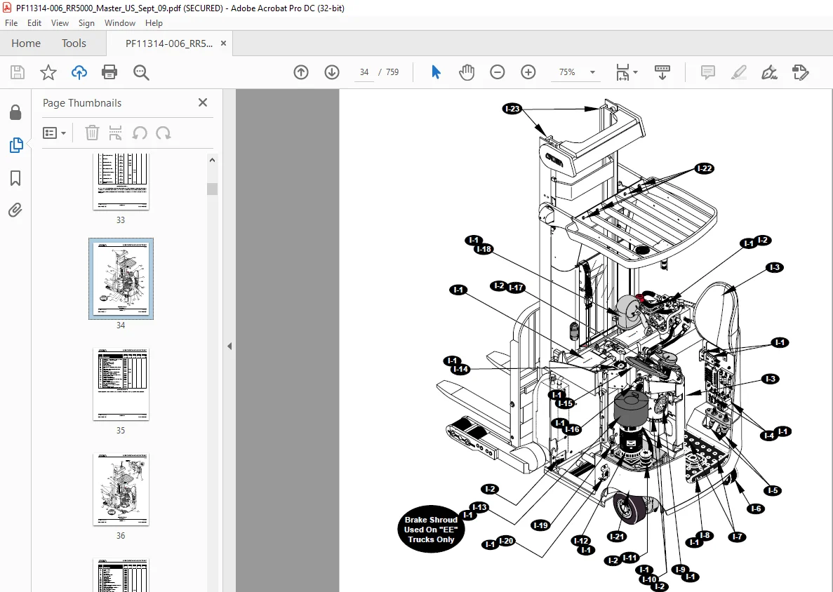
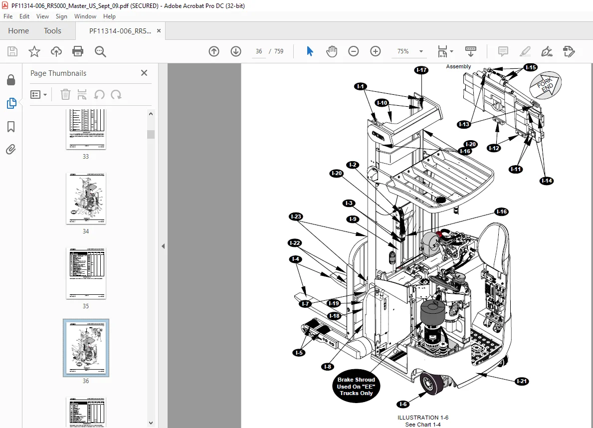
IMAGES PREVIEW OF THE MANUAL:
Customer Support: [email protected]
S.M 5/24