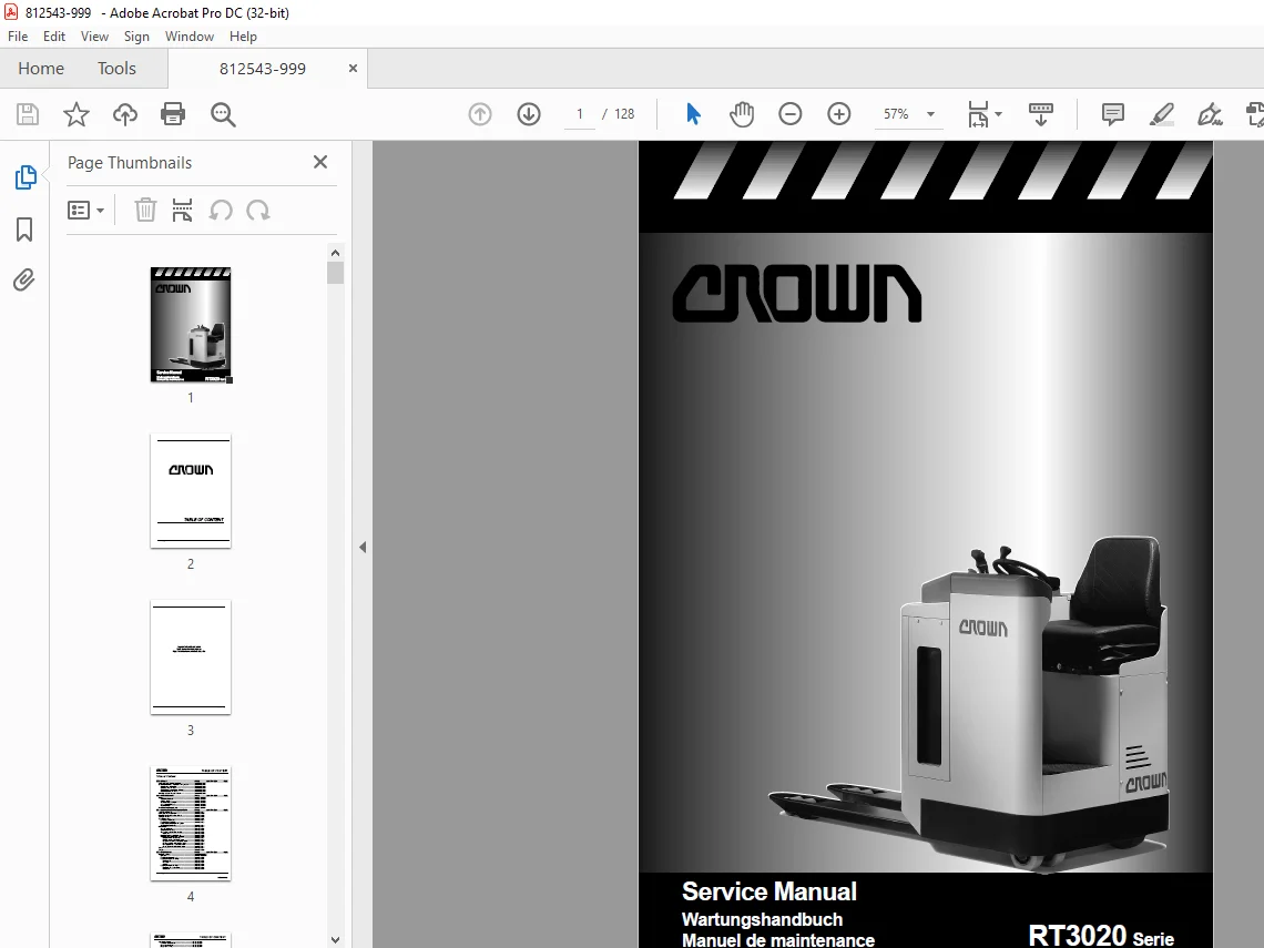
Crown Forklift RT3020 Serie Service Manual – PDF DOWNLOAD
$27.95
Crown Forklift RT3020 Serie Service Manual – PDF DOWNLOAD
Description
Crown Forklift RT3020 Serie Service Manual – PDF DOWNLOAD
FILE DETAILS:
Crown Forklift RT3020 Serie Service Manual – PDF DOWNLOAD
Language : English
Pages :128
Downloadable : Yes
File Type : PDF
TABLE OF CONTENTS:
Crown Forklift RT3020 Serie Service Manual – PDF DOWNLOAD
MA – SAFETY PAGE SER-NR CUT REV
Safety Symbols used in the Manual M/P-MA-0000-001
General Maintenance and Repair Safety Notes M/P-MA-0000-001
– Maintenance and Repair M/P-MA-0000-002
– Before Leaving the Truck M/P-MA-0000-002
– Before Carrying out Work on the Truck M/P-MA-0000-002
– Before Operating the Truck M/P-MA-0000-002
Warnings and Labels on the Truck M/P-MA-0000-002
ITD – INTRODUCTION PAGE SER-NR CUT REV
General M/P-ITD-2900-001
– Operating instruction M/P-ITD-2900-001
– Service training M/P-ITD-2900-001
– Replacement parts orders M/P-ITD-2900-001
– Structure of the Manual M/P-ITD-2900-001
– Page Numbers M/P-ITD-2900-002
Truck Data Numbering Sheet M/P-ITD-2900-004
M1 – LUBRICATION AND ADJUSTMENT PAGE SER-NR CUT REV
Jacking up the Truck M-10-2900-001
Raising the Truck with a Crane M-10-2900-002
Lifting the Truck with a second Truck M-10-2900-002
Towing the Truck M-10-2900-002
Component Access M-10-2900-003
Removing the Floorboard M-10-2900-005
Removing the Side Panel M-10-2900-005
Access to Drive Unit, Hydraulic System
and Electrical Components M-10-2900-005
Maintenance M-11-2900-001
– Driver Participation M-11-2900-001
– Daily Maintenance Log M-11-2900-001
– Recommended Lubricants and Oils M-11-2900-001
– Lubricants M-11-2900-002
Grease items and grease intervals M-12-2900-002
– Inspection and Maintenance Schedule M-12-2900-002
– Daily or every 8 service hours M-12-2900-003
– Monthly or every 100 service hours M-12-2900-005
– Every three months or 250 service hours M-12-2900-007
– Every six months or 500 service hours M-12-2900-009
– Annually or every 1000 service hours M-12-2900-011
– Every 2 years or 2000 service hours M-12-2900-011
Caster M-15-2900-001
Torques M-19-2900-002
M2 – HYDRAULICS PAGE SER-NR CUT REV
Hydraulic System M/P-M21-2900-001
Operation M/P-M21-2900-001
Removing the Hydraulic Unit M-22-2900-001
Replacing the Hydraulic Pump M-23-2900-001
– Disassembly M-23-2900-001
– Assembly M-23-2900-001
– Start-up M-23-2900-001
Replacing the Hydraulic Filter M-23-2900-001
– Replacing the Suction Filter M-23-2900-001
– Oil Change M-23-2900-002
Printed in Germany
M-IDX-2900-002
TABLE OF CONTENT
Valve Setting Control M-23-2900-004
Non-return valve control M-23-2900-004
Safety Valve Control M-23-2900-004
Safety Valve Setting M-23-2900-004
M3 – DRIVE UNIT PAGE SER-NR CUT REV
Gear Unit M-31-2900-001
Preparation M-31-2900-001
Maintenance M-31-2900-002
– General M-31-2900-002
Drive Unit Disassembly M-31-2900-003
Assembly M-31-2900-003
Adjusting the Bevel Wheel Set M-31-2900-004
Final Assembly M-31-2900-004
Drive Unit Re-Installation M-31-2900-005
Live Ring Bearing Replacement M-31-2900-005
Forcing out the Live Ring Bearing M-31-2900-005
Pressing in the Live Ring Bearing M-31-2900-005
Installation of the Live Ring Bearing in the Drive Unit M-31-2900-005
M4 – ELECTRICS PAGE SER-NR CUT REV
Electrical Components M-42-2900-001
Transmitter (MC,MN,PT) M-42-2900-001
Fast / Slow Switch (HES) M-42-2900-001
Safety Pedal (PCT) M-42-2900-001
Lift / Lower Switch (PCS, PCD) M-42-2900-001
Lift Limit Switch (MFF) M-42-2900-001
Pressure Switch (PS) M-42-2900-001
Horn Switch (PCX) M-42-2900-001
Horn (CX) M-42-2900-001
Key Switch (QC) M-42-2900-001
Emergency Disconnect Switch (PE) M-42-2900-001
Steering Angle-Dependent Speed Reduction Microswitch M-42-2900-001
Brake (FE) M-42-2900-002
Fuses (F1, F2, FA) M-42-2900-002
Traction Motor (M1) M-42-2900-002
Pump Motor (M2) M-42-2900-002
Pump Contactor (K3) M-42-2900-002
Main Contactor (K4) M-42-2900-002
Raise Contactor (RLS) and Lower Contactor (RLD) M-42-2900-002
OPTION Steering Motor (M3) M-42-2900-002
OPTION Encoder (MS) M-42-2900-002
OPTION Limit Switch (MF) M-42-2900-002
OPTION Steering-Contactor (K6) M-42-2900-002
OPTION Fuses (F3, FA3) M-42-2900-002
Travel Direction Display M-42-2900-002
ES1 Traction Controller M-43-2900-001
General M-43-2900-001
– Precautionary Measures M-43-2900-001
Operational Features M-43-2900-001
– Speed Control M-43-2900-001
– Reduced Speed Range M-43-2900-001
– Downhill Speed Control M-43-2900-001
– Regenerative Braking M-43-2900-001
– Anti-Roll-Down-Function M-43-2900-001
Printed in Germany
M-IDX-2900-003
TABLE OF CONTENT
– Hourmeter M-43-2900-002
Self Test M-43-2900-002
– Monitored Circuits M-43-2900-002
Protective Devices M-43-2900-003
– Polarity Protection M-43-2900-003
– Wiring Errors M-43-2900-003
– Temperature M-43-2900-003
– Start Sequence M-43-2900-003
– Safety Class M-43-2900-003
Maintenance M-43-2900-003
ES1 Traction Controller Connections M-43-2900-004
Programmer M-44-2900-001
General M-44-2900-001
Operating Menu ES1 Controller M-44-2900-002
– General M-44-2900-002
– Menu Functions M-44-2900-002
– Operating Menu – Overview M-44-2900-003
Adjustment M-45-2900-001
– Menu PARAMETER CHANGE M-45-2900-001
– Max Speed Setting M-45-2900-002
– TESTER Menu M-45-2900-004
– Error Code Display in SAM Hourmeter M-45-2900-006
– ALARMS Menu M-45-2900-006
– PROGRAM VACC Menu M-45-2900-009
CONFIG Menu M-45-2900-010
SAM Hourmeter M-45-2900-01
Traction Controller Replacement and Transfer of
Service Hours into the new Controller: M-45-2900-011
Traction Controller Safety Test M-420-2900-001
Battery M-425-2900-001
General M-425-2900-001
Operation M-425-2900-001
Battery Replacement M-425-2900-001
Battery Removal M-425-2900-001
– Replacing the Battery with a Crane M-425-2900-002
– Replacing the Battery with a Battery Trolley M-425-2900-003
Charging the Battery M-425-2900-004
Electric Motors M-435-2900-001
General Maintenance Instructions M-435-2900-001
Preparation M-435-2900-001
Important Maintenance Instructions M-435-2900-001
Traction Motor Maintenance M-435-2900-002
Access to the Brushes M-435-2900-002
Maintenance M-435-2900-002
– Armature M-435-2900-002
– Bearings M-435-2900-002
Pump Motor Maintenance M-435-2900-003
Access to the Brushes M-435-2900-003
Maintenance M-435-2900-003
OPTION Steering Motor Maintenance M-435-2900-004
Access to the Brushes M-435-2900-004
Maintenance M-435-2900-004
Printed in Germany
M-IDX-2900-004
TABLE OF CONTENT
M-5 – BRAKE PAGE SER-NR CUT REV
Brake M-50-2900-001
– Function M-50-2900-001
– Removal M-50-2900-001
– Assembly M-50-2900-002
– Air Gap Setting M-50-2900-002
– Brake Moment Setting M-50-2900-002
– Brake Test M-50-2900-003
M6 – STEERING PAGE SER-NR CUT REV
Steering M-61-2900-001
Operation M-61-2900-001
Lower Steering Chain Adjustment M-61-2900-002
Adjusting the Drive Unit Steering Chain M-61-2900-002
Checking the Sliding Clutch M-61-2900-003
Replacing the Sliding Clutch M-61-2900-003
OPTION Steering Sensor Removal / Installation M-61-2900-004
OPTION Steering Motor Removal / Installation M-61-2900-004
OPTION Limit Switch Removal / Installation M-61-2900-004
M7 – LIFTING MECHANISM PAGE SER-NR CUT REV
Lifting Mechanism M-70-2900-001
Test M-70-2900-001
Adjusting the Stop M-70-2900-001
M8 – CYLINDERS PAGE SER-NR CUT REV
Cylinders M-80-0000-001
General M-80-0000-001
Plunger Cylinders (single-acting) M-80-0000-001
Piston Cylinder (Double-Acting Cylinder) M-80-0000-002
Maintenance M-80-0000-004
Inspection M-80-0000-001
Seal Installation M-86-2900-001
General M-86-2900-001
Lift Cylinder M-86-2900-001
Removal Preparation M-86-2900-001
Removal M-86-2900-001
Repairing the Lift Cylinder M-86-2900-002
– Disassembly M-86-2900-002
– Inspection M-86-2900-002
– Assembly M-86-2900-002
Assembly M-86-2900-002
Gas Pressure Spring Removal and Assembly M-86-2900-003
– Removal Preparation M-86-2900-003
– Removal M-86-2900-003
– Assembly M-86-2900-003
DIA – ELECTRICAL DIAGRAMS PAGE SER-NR CUT REV
Standard Version M/P-DIA-2900-001
OPTION With electrical steering M/P-DIA-2900-002
HYD – HYDRAULIC SCHEMATIC PAGE SER-NR CUT REV
Hydraulic Schematic
IMAGES PREVIEW OF THE MANUAL:
S.M 5/24