Crown Forklift RT3020 Service Manual PDF
$27.95
Crown Forklift RT3020 Service Manual – PDF DOWNLOAD
Description
Crown Forklift RT3020 Service Manual – PDF DOWNLOAD
FILE DETAILS:
Crown Forklift RT3020 Service Manual – PDF DOWNLOAD
Language : English
Pages :128
Downloadable : Yes
File Type : PDF
TABLE OF CONTENTS:
Crown Forklift RT3020 Service Manual – PDF DOWNLOAD
RT3020 1
TABLE OF CONTENT 2
M-IDX-2900-001 4
M-IDX-2900-002 5
M-IDX-2900-003 6
M-IDX-2900-004 7
SAFETY 8
Safety Symbols used in the Manual 10
General Maintenance and Repair Safety Notes 10
Maintenance and Repair 10
Before Leaving the Truck 11
Before Carrying out Work on the Truck 11
Before Operating the Truck 11
Warnings and Labels on the Truck 11
INTRODUCTION 12
General 14
Operating Instructions 14
Service Training 14
Ordering Spare Parts 14
Using the Manual 14
Page Numbering in the Manual 15
Model-Number 16
LUBRICATION AND ADJUSTMENT 18
Jacking up the Truck 20
Pictures 20
Raising the Truck with a Crane 21
Lifting the Truck with a second Truck 21
Towing the Truck 21
Component Access 22
Picture 22
Component Access, Picture 23
Removing the Floorboard 24
Removing the Side Panel 24
Access to Drive Unit, Hydraulic System and Electrical Components 24
Maintenance 25
Driver Participation 25
Daily Maintenance Log 25
Recommended Lubricants and Oils 25
Lubricants 25
Cold Store Trucks 25
Type Lubricant 26
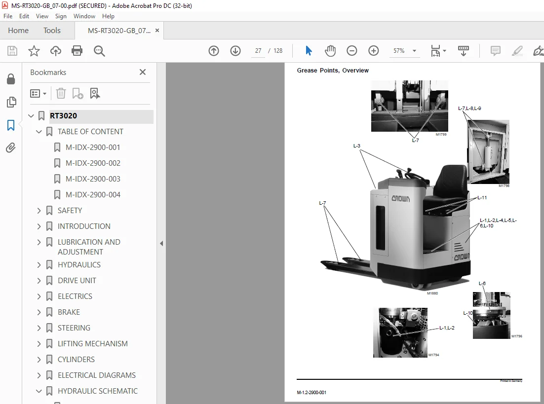
Grease Points, Overview 27
Grease Points / Intervals 28
Inspection and Maintenance Schedule 28
Battery Maintenance 28
Daily or every 8 service hours 29
Picture 30
Monthly or every 100 service hours 31
Picture 32
Every three months or 250 service hours 33
Picture 34
Every six months or 500 service hours 35
Picture 36
Annually or every 1000 service hours 37
Every 2 years or 2000 service hours 37
Picture 38
Caster 39
Torques 40
HYDRAULICS 42
Hydraulic System 44
Operation 44
Diagram 44
Removing the Hydraulic Unit 45
Picture 45
Replacing the Hydraulic Pump 46
Disassembly 46
Assembly 46
Start-up 46
Pump Motor 46
Replacing the Hydraulic Filter 46
Replacing the Suction Filter 46
Oil Change 47
Diagram 48
Valve Setting Control 49
Non-return valve control 49
Safety Valve Control 49
Safety Valve Setting 49
Picture 50
DRIVE UNIT 52
Drive Unit 54
Preparation 54
Removal 54
Maintenance 55
General 55
Drive Unit Disassembly 56
Assembly 56
Adjusting the Bevel Wheel Set 57
Basic Rules 57
Checking the Flank Bearing 57
Final Assembly 57
Drive Unit Re-Installation 58
Live Ring Bearing Replacement 58
Forcing out the Live Ring Bearing 58
Pressing in the Live Ring Bearing 59
Installation of the Live Ring Bearing in the Drive Unit 59
ELECTRICS 60
Electrical Components 62
Transmitter (MC,MN,PT) 62
Fast / Slow Switch (HES) 62
Seat Switch (MPD) 62
Safety Pedal (PCT) 62
Lift / Lower Switch (PCS, PCD) 62
Lift Limit Switch (MFF) 62
Pressure Switch (PS) 62
Horn Switch (PCX) 62
Horn (CX) 62
Key Switch (QC) 62
Emergency Disconnect Switch (PE) 62
Steering Angle-Dependent Speed Reduction Microswitch 62
Brake (FE) 63
Fuses (F1, F2, FA) 63
Traction Motor (M1) 63
Pump Motor (M2) 63
Pump Contactor (K3) 63
Main Contactor (K4) 63
Raise Contactor (RLS) and Lower Contactor (RLD) 63
Steering Motor (M3), Option 63
Encoder (MS), Option 63
Steering Limit Switch (MF), Option 63
Steering-Contactor (K6), Option 63
Fuses (F3, FA3), Option 63
Travel Direction Display (STD) 63
Picture 64
Picture 65
ES1 Traction Controller 66
General 66
Precautionary Measures 66
Operational Features 66
Speed Control 66
Reduced Speed Range 66
Downhill Speed Control 66
Regenerative Braking 66
Anti – Roll Down Function 66
Hourmeter 67
Self Test 67
Monitored Circuits 67
Diagram 67
Protective Devices 68
Polarity Protection 68
Wiring Errors 68
Temperature 68
Start Sequence 68
Safety Class 68
Maintenance 68
ES1 Traction Controller Connections 69
Programmer 70
General 70
Diagram 70
Description of keys 71
Operating Menu ZAPI ES1 Controller 71
General 71
Menu Functions 71
Operating Menu – Overview 72
PARAMETER CHANGE Menu 73
Max Speed Setting 74
Speed Measurement 75
TESTER Menu 76
ALARMS Menu 77
Error Code Display in SAM Hourmeter 77
ALARMS Menu, diagram 78
PROGRAM VACC Menu 80
CONFIG Menu 81
SAM Hourmeter 82
Traction Controller Safety Test 83
Battery 84
General 84
Operation 84
Battery Replacement 84
Battery Removal 84
Replacing the Battery with a Crane 85
Replacing the Battery with a Battery Trolley 86
Charging the Battery 87
Electric Motors 88
General Maintenance Instructions 88
Preparation 88
Important Maintenance Instructions 88
Traction Motor Maintenance 89
Access to the brushes 89
Maintenance 89
Armature 89
Bearings 89
Pump Motor Maintenance 90
Access to the Brushes 90
Maintenance 90
Steering Motor Maintenance 91
Access to the Brushes 91
Maintenance 91
BRAKE 92
Brake 94
General Functional Description 94
Removal 94
Assembly 95
Air Gap Setting 95
Brake Moment Setting 95
Brake Test 96
RT3010 Nominal Braking Distances and Screw Depth 96
STEERING 98
Steering100
Operation100
Option100
Diagram100
Lower Steering Chain Adjustment101
Adjusting the Drive Unit Steering Chain101
Checking the Sliding Clutch102
Replacing the Sliding Clutch102
Steering Sensor Removal / Installation103
Steering Motor Removal / Installation103
Limit Switch Removal / Installation103
Diagram104
LIFTING MECHANISM106
Lifting Mechanism108
Test108
Adjusting the Stop108
Diagram109
CYLINDERS110
Cylinders112
General112
Plunger Cylinders (single-acting)112
Piston Cylinder (Double-Acting Cylinder)113
Single-Acting Cylinder, Picture114
Double-Acting Cylinder, Picture114
Maintenance115
Inspection115
Seal Installation116
General116
Lift Cylinder116
Removal Preparation116
Removal116
Repairing the Lift Cylinder117
Disassembly117
Inspection117
Assembly117
Assembly117
Gas Pressure Spring Removal and Assembly118
Removal Preparation118
Removal118
Assembly118
ELECTRICAL DIAGRAMS120
Control Circut122
Control Circut/Steering Motor123
HYDRAULIC SCHEMATIC124
Diagram126
IMAGES PREVIEW OF THE MANUAL:
S.M 5/24