Crown Forklift SC3000 Series Service Manual – PDF DOWNLOAD
$26.95
Crown Forklift SC3000 Series Service Manual – PDF DOWNLOAD
Description
Crown Forklift SC3000 Series Service Manual – PDF DOWNLOAD
FILE DETAILS:
Crown Forklift SC3000 Series Service Manual – PDF DOWNLOAD
Language : English
Pages :178
Downloadable : Yes
File Type : PDF
TABLE OF CONTENTS:
Crown Forklift SC3000 Series Service Manual – PDF DOWNLOAD
SC3000 1
TABLE OF CONTENT 2
IDX-2230-001 4
IDX-2230-002 5
IDX-2230-003 6
IDX-2230-004 7
IDX-2230-005 8
IDX-2230-006 9
SAFETY 10
Safety Symbols used in the Manual 12
General Maintenance and Repair Safety Notes 12
Maintenance and Repair 12
Before Leaving the Truck 13
Before Carrying out Work on the Truck 13
Before Operating the Truck 13
Warnings and Labels on the Truck 13
INTRODUCTION 14
Introduction 16
General 16
Using the Manual 16
Sections Maintenance 17
Page Numbers 18
Operating instruction 18
Service training 18
Replacement parts orders 18
Truck Data Numbering Sheet 19
NOTE 19
Battery Options 20
NOTE 20
LUBRICATION AND ADJUSTMENT 22
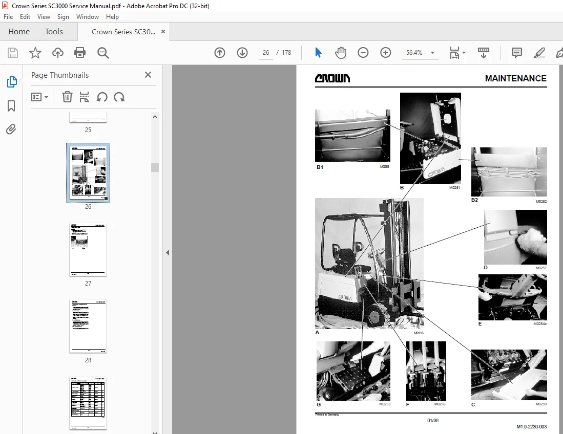
Lubrication and Adjustment 24
Access to Components 24
Fig B 24
Figs B1 and B2 24
Fig C 24
Fig D 24
Fig E 24
Fig F 25
Fig G 25
Pictures (all) 26
Jacking up the Truck 27
Recommended Lubricants and Oils 28
Lubricants 28
Cold Store Trucks 28
Driver Participation 28
Daily Maintenance Log 28
Lubricants and Oil Recommendations 29
Inspection and Maintenance Schedule 30
Daily or every 8 service hours 31
Picture 32
Monthly or ever 100 service hours 33
Picture 34
Every three months or 250 service hours 35
Picture 36
Annually or every 1000 service hours 37
Picture 38
Lubrication Points / Intervals 39
Picture 40
Torques 41
Standard Screws and Nuts 42
Umbrako Screws and Nuts 42
Torques 43
Torques (contd) 44
HYDRAULICS 46
Hydraulic Symbols 48
Hydraulic System 52
General 52
Hydraulic system diagram 53
Operational Description 54
Idle Mode 54
Priority Valve 54
Steering 54
Lifting 54
Tilting 54
Control Valve 55
Main Relief Valve Setting 55
Maintenance and Repairs 55
Pilot Valve Troubleshooting 55
Unscrew valve cartridges 56
Pump Motor 57
Hydraulic Pump 57
Commissioning 57
Bleeding 57
Oil Change 57
DRIVE UNIT 58
Truck Drive System 60
Gear Unit 60
Removal 60
Drive Motor 60
Removal 60
Design 61
Spur wheel bevel gear assembly 61
Pre-assembly of the housing with flange shaft 61
Bevel gear spur wheel pinion shaft pre-assembly 61
Spur wheel flange shaft assembly 61
Bevel gear assembly 62
Bevel pinion assembly 62
Flank tooth bearing 63
Correcting the flank tooth bearing 63
Reducing the installation path of the conical pinion 63
Increasing the installation path of the conical pinion 63
Maintenance 64
Adding oil 64
Types of oil 64
Oil level 64
Oil change 64
ELECTRICS 66
Electrical System 68
Wire Colour Codes 68
Tabel 68
Switch Symbol Abbreviation List 69
Sundry Abbreviations 70
Electrical Symbols 71
Electrical Components 72
Switch Functions 72
Brake Switch (BRS) 72
Encoder (ENC), Encoder Module (EM) 72
Accelerator Pedal Switch (ACS, POT1) 72
Direction Indicator Switch (DIS) 72
Handbrake Switch (HBS) 72
Raise Potentiometer (POT2) 72
Steering Axle Potentiometer (POT3) 72
Tilt (TLT), Sideshift (SSS), Auxiliary Switch (AXS) 72
Emergency Disconnect 72
Key Switch (KYS) 72
Fuses (FU) 72
Seat Switch (SES) 73
Horn Switch (HNS) 73
Electrical Components – Overview 73
Zapimos B1S 48/700 Controller 74
General 74
Main Features 74
Protective Devices 74
Polarity Protection 74
Wiring Errors 74
Overheating 74
Protection 74
Key Terms 74
Shunt or Shunt Resistor (+SH/-SH) 74
Volt Motor Negative (VMN) 74
Functional Description 75
Acceleration / Delay Rate 75
Travel Switch 75
Travel Switch Signal Response 75
Fault Log 75
Fault Identification 75
Sparkless Contactors 75
Inversion Braking 75
Creep Mode 75
Slow Travel 75
Steering Controller 75
45° Steering Angle 76
MOSFET 76
Pedal Braking (Inversion Braking with Battery Supply Regeneration) 76
Pulse Width Modulation (PWM) 76
Ramp Start 76
Key Switch 76
Self Test 76
Reverse Travel Alarm 76
Seat Switch 76
Current Limit 76
Overvoltage 76
Overheating 76
Low Voltage Reduction 76
Connections ZAPIMOS B1S 48/700 Traction Controller 77
Programmer Connection “B” 78
Status LED “A” 78
Status LED Diagnosis 78
LED Code 78
Control Line Connections 79
ZAPIMOS B1S 48/700 Pin Layout 80
Maintenance 81
Cleaning the Traction Controller 81
Removing / Installing the Traction Controller 81
Installing the Traction Controller 82
Zapimos HP 350A Pump Controller 83
General 83
Protective Devices 83
Polarity Protection 83
Wiring Errors 83
Overheating 83
Protection 83
Key Terms 83
Shunt or Shunt Resistor (+SH/-SH) 83
Volt Motor Negative (VMN) 83
Functional Description 84
Acceleration / Delay Rate 84
Current Limit 84
Fault Identification 84
Fault Log 84
Hydraulic Function Switch 84
Key Switch 84
Lift Cut-Out 84
Lift Potentiometer 84
Lift Potentiometer Response 84
Low Voltage Reduction 84
MOSFET 84
Overheating 84
Overvoltage 84
Pulse Width Modulation (PWM) 84
Seat Switch 85
Self Test 85
Steer Support 85
Connections ZAPIMOS HP 350A Pump Controller 85
Programmer Connection “B” 86
Status LED “A” 86
Status LED Diagnosis 86
LED Code 86
ZAPIMOS HP 350 A Pin Layout 87
Maintenance 87
Cleaning the Pump Controller 87
Removing / Installing the Pump Controller 88
Programmer 90
General 90
Description of keys 91
Connecting the Programmer 92
Operating Menu 92
Traction Controller Operating Menu 93
Programmer Start Routine 94
Traction Controller Menu Functions 95
PROGRAM 95
TESTER 95
ALARMS 95
PROGRAM PEDAL 95
CONFIG 95
PROGRAM Menu 96
TESTER Menu 97
ALARMS Menu 98
ALARMS Menu (continued) 99
PROGRAM PEDAL Menu 99
CONFIG Menu100
Pump Controller Operating Menu101
Menu Functions Pump Controller102
PROGRAM102
TESTER102
ALARMS102
PROGRAM VACC102
CONFIG102
PROGRAM Menu103
TESTER Menu104
ALARMS Menu105
ALARMS Menu (continued)106
CONFIG Menu107
Traction Controller Safety Test108
Pulse Monitor Trip Test (PMT)108
PMT Safety Test Wiring109
Battery110
General110
Operation110
Reading the Electrolyte Level110
Replacing the Battery110
Removing the Battery110
Charging the Battery110
Battery Discharge Indicator (BDI)112
General112
Adjusting the Battery Discharge Indicator112
Traction / Pump Motor Maintenance113
Access113
BRAKE114
Brake System116
General116
Operation116
Picture116
Replacing the Brake Disks and Linings117
Preparation117
Fig M0253b117
Fig M0254b117
Brake Disk and Lining Dimensions118
Removing the Brake Disks and the Friction Plates119
M0362120
Removing the Handbrake Cable121
Installation121
Adjusting the Operating Brake and Handbrake121
Preparation121
Adjusting the Operating Brake Air Gap121
Operating Brake Test122
Handbrake Adjustment122
STEERING124
Steering126
Hydraulic System126
Components126
Removing the Steering Motor127
Steering System Hydraulic Diagram127
Steering Axle128
Design128
Steering Drive Assembly128
Wheel hub pre-assembly128
Steering knuckle pre-assembly128
Steering knuckle and wheel hub assembly128
Spur pinion wheel shaft pre-assembly129
Housing Pre-Assembly129
Setting the Bearing Play130
Cylinder Pre-Assembly133
Fitting the Cylinders133
Assembling the Axle Bracket to the Steering Drive133
Operational and Leak Test133
Maintenance134
General134
Gear Lubricant134
Seals134
MAST136
Mast138
Disassembly138
Mast Roller Adjustment138
Fork Carriage Roller Adjustment140
Mast Roller Adjustment141
Checking the Mast Play141
Lift Chain Test142
General142
Maintenance142
Detailed Chain Testing143
Worn or Missing Plates143
Pitting and Corrosion143
Protruding or Turned Chain Pins143
Freedom of Movement and Worn Edges143
Measuring the Chain Elongation144
Chain Tension144
Chain Anchor and Pulleys144
Fork Tine Test145
General145
Fork Identification145
Repairs145
Crack Inspection145
VerticalityTest146
Fork Blade Warping146
Measuring the Fork Tip Width147
Fork Tine Height Difference147
Fork Stop147
Wear148
CYLINDERS150
Cylinders152
General152
Plunger Cylinders (single-acting cylinders)152
Piston Cylinder (Double-Acting Cylinder)153
Maintenance155
Inspection155
Installing the Piston Seal156
General156
Rod Seal Disassembly Tool156
Assembly of Small Rod Seals156
Assembly of Large Rod Seals156
ELECTRICAL DIAGRAMS158
Key160
Connectors160
Contactors160
Abbreviations160
Control Circuit161
Power Circuit162
Traction Controller163
Pump Controller164
Seat Switch and Steer Pot165
Control Levers166
BDI, Horn and Brake Switches167
Steer Column168
Star Points169
Panel Wiring170
Power Cables171
Part Numbers for Connectors and Looms172
HYDRAULIC SCHEMATIC174
Diagram176
IMAGES PREVIEW OF THE MANUAL:
S.M 5/24