Crown Forklift TC3000 Series Maintenance Manual – PDF DOWNLOAD
$26.95
Crown Forklift TC3000 Series Maintenance Manual – PDF DOWNLOAD
Description
Crown Forklift TC3000 Series Maintenance Manual – PDF DOWNLOAD
FILE DETAILS:
Crown Forklift TC3000 Series Maintenance Manual – PDF DOWNLOAD
Language : English
Pages :216
Downloadable : Yes
File Type : PDF
TABLE OF CONTENTS:
Crown Forklift TC3000 Series Maintenance Manual – PDF DOWNLOAD
SAFETY PAGE SERIAL NO CUT REV
Description of Symbols and Indicators 3
Safety Notices 3
Other indicators 3
General Safety Instructions 4
Maintenance and Repair Instructions 4
Maintenance and Repairs 4
Before Parking the Truck 4
Before Working on the Truck 4
Before Starting the Truck 4
Warning and Instruction Decals on the Truck 5
INTRODUCTION PAGE SERIAL NO CUT REV
General 9
Service Training 9
Replacement Parts 9
Additional Attachments and Modifications 9
Using the Manual 9
Contact Address 9
Models 10
LUBRICATION & ADJUSTMENT PAGE SERIAL NO CUT REV
Lifting and Jacking up the Truck 13
Lifting the Truck 13
Lifting the truck with a crane 13
Lifting the truck with a forklift truck 13
Jacking up the Truck 14
Towing the Truck 15
Taking the Truck out of Service 16
Testing Re-Commissioned Trucks 16
Restoring the Truck to Service 16
Recommended Lubricants and Accessories 17
Cold Store Trucks 17
Planned Maintenance 19
Inspection and Lubrication Points 22
Torques 24
Standard Torques 24
Castor Wheels and Skids 25
Adjusting the Castor Wheels and Skids 26
DRIVE UNIT PAGE SERIAL NO CUT REV
Changing the Transmission Oil 29
Components 31
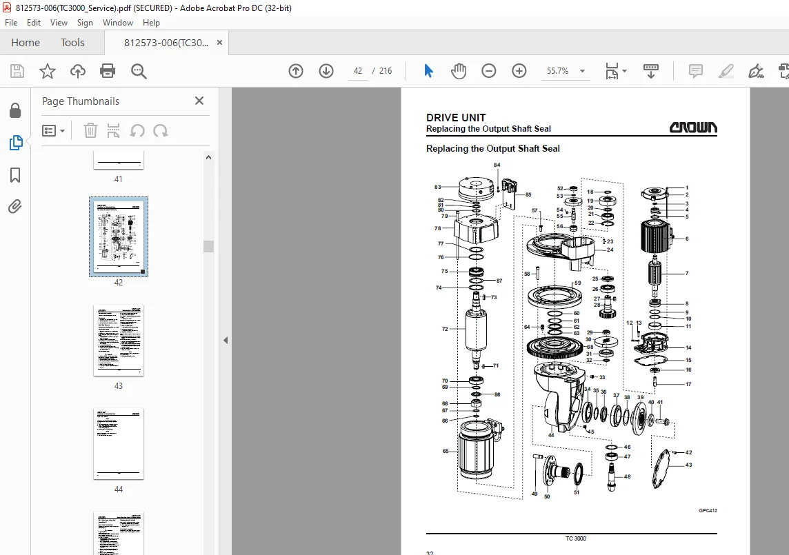
Replacing the Output Shaft Seal 32
Special Tools Required 33
Preparation 33
Shaft Seal Removal 33
Output shaft removal 33
Output shaft assembly 33
Drive Wheel and Wheel Bolt Replacement 35
Drive Wheel Disassembly 35
Replacing the Wheel Bolts 35
Drive Wheel Assembly 35
Replacing the Drive Unit 36
Special Tools Required 36
Drive Unit Removal 36
Drive Unit Installation 36
Repairing the Drive Transmission Unit 37
Preparation 38
Drive Transmission Unit Disassembly 38
Output shaft removal 38
Bevel gear and bevel pinion removal 38
Drive Transmission Unit Assembly 39
Bevel pinion and drive pinion assembly 39
Bevel gear assembly 40
ELECTRICAL SYSTEM PAGE SERIAL NO CUT REV
General 45
Wire Colour Code 45
Contact Symbol Abbreviations 46
Electrical Wiring Diagrams 48
Components 50
Operator Menu 54
Operator Menu 55
Service Menu 56
Analyzer Menu – Status & Inputs 57
Analyzer Menu – Outputs 58
Analyzer Menu – Access 2 Inputs 60
Analyzer Menu – Access 3 Inputs 61
Analyzer Menu – Access 3 Inputs 62
Analyzer Menu – Access 5 Inputs 63
Analyzer Menu – Test Outputs 64
Calibration – Rocker & Load Sensor 65
Calibration – Steer System 66
Features 67
Features 68
Features 69
Features 70
Features 71
Hours 72
Events 73
Events 74
Performance 75
Performance 76
Performance 77
Performance 78
Performance 79
Utilities 80
Parameter Setting 81
Calibration 82
Selecting the CALIBRATION Menu 82
Calibrating the Traction Potentiometer 82
Steering Calibration 82
Control Modules 84
General 84
Power Fuses 84
Servicing and Replacing the Control Modules 85
Discharging the Capacitors 85
Servicing the Control Modules 85
Replacing Control Modules 85
Removal 85
Assembly 85
Event Codes – Access 3 87
Event Codes – Access 5 94
Drive Motor 102
Drive Motor Disassembly 103
Drive Motor Assembly 103
Repairing the Drive Motor 104
Preparation 104
Dismantling the Rotor Assembly 104
Assembling the Rotor Assembly 104
Final task: 104
Steer Motor 105
Special Tools Required 106
Steer Motor Disassembly 106
Steer Motor Assembly 106
Repairing the Steer Motor 106
Preparation 106
Steer Motor Disassembly 106
Steer Motor Assembly 106
Final tasks: 106
Battery 107
General 107
Charging the Battery 107
Replacing the Battery 107
Contactors – Inspection and Repairs 108
Inspection 108
Contacts 108
Coils 108
Springs 108
Servicing 109
Dismantling 109
Assembly 109
Control Module Safety Test 110
General 110
Required tools 110
Carrying out the PMT 110
Testing Access 3 (TCM) 110
Testing Access 5 (SCM) 110
BRAKE SYSTEM PAGE SERIAL NO CUT REV
Electromechanical Brake 115
General 115
Servicing the Brake 115
Measuring the air gap 115
Repairing the Brake 116
Installing a wear part kit 116
Replacing the brake in full 118
STEERING PAGE SERIAL NO CUT REV
Steering Assembly Installation and Removal 123
Steering Assembly Components 124
Steering Assembly Removal 124
Steering Assembly Installation 124
Final Tasks 124
Steering Transmission Repair 125
Preparation 125
Steering Transmission Disassembly 125
Steering Transmission Assembly 125
Final tasks 126
Tiller Handle Components 127
Tiller Handle Shell Removal and Assembly 128
Tools Required 128
Preparation 128
Shell Removal 128
Shell Assembly 129
Switch Unit Removal / Assembly 130
Components 130
Switch Unit Disassembly 130
Switch Unit Assembly 130
“Rabbit / Turtle” Toggle Module Removal and Assembly 131
“Rabbit/Turtle” Toggle Module Disassembly 131
“Rabbit/Turtle” Toggle Module Assembly 131
Replacing the Tiller Handle PC Boards 132
Hydraulic PC Board Removal 132
Hydraulic PC Board Assembly 132
Main PC Board Disassembly 132
Main PC Board Assembly 132
Traction Potentiometer Removal and Assembly
(POT Travel Switch) 133
Traction Potentiometer Removal 133
Traction Potentiometer Assembly 134
Traction Potentiometer Calibration 134
Safety Reverse Switch Removal and Assembly 135
Safety Reverse Switch Removal 135
Safety Reverse Switch Assembly 136
Grip and Horn Switch Removal and Assembly 137
Control Handle Overview 138
Tiller Removal / Assembly 139
Tiller Removal 139
Tiller Assembly 139
Tiller Recuperating Spring Removal / Assembly 140
Recuperating Spring Removal 140
Recuperating Spring Assembly 140
Steer Sensor Removal / Assembly 141
Steer Sensor Removal 141
Steer Sensor Assembly 141
Testing the Steer Sensor via the Analyzer Menu 142
Steering Calibration 143
Platform Overview 147
Replacing the Platform Sensors 148
Platform Sensor Removal 148
Platform Sensor Assembly 148
Platform Assembly and Testing the Platform Sensors 148
Testing the Platform Sensors via the Analyzer Menu 148
Possible error cause 149
SCHEMATIC DIAGRAMS PAGE SERIAL NO CUT REV
Overview 153
With Key Switch and Keypad 154
Access™ 3/2 – Drive Side 155
Access 2/3 – Logic Side 156
Access 5 – Logic Side 157
Access 81 – Tiller 158
Access 82 – Backrest 159
Switch Connection 160
Tiller Circuits 161
Access 1 with Options 162
CAN connection 163
Abbreviation List 164
Connectors and Sockets 164
Switches and Sensors 167
Components 168
Wires and Wire Harnesses 169
Fuses and Fuse Holders 169
Drives 170
Power Cables 171
Wire Harness – Hitch Position Control Switch 172
Assembly – Hitch Position Control Switch 174
Wire Harness – Hitch Position Control Switch F/C 175
Horn Wire Harness 177
Horn Switch Assembly 178
Assembly – SAS Switch 179
Main Harness 180
Spline Overview 184
X10 Handle Wire Harness 185
Display Wire Harness 187
Programmer Connector 189
CAN Handle Connection Wire Harness 190
Steer Sensor Assembly 191
Straight Ahead Sensor 192
Battery lock switch (BLS) 193
Key Switch Adapter 194
DC / DC Converter Connector Cable 195
DC / DC Converter 196
Power Supply Cables 197
Strobe Wire Harness 198
Keypad Adapter 199
CAN Bus and Fuse Cable Extension 200
CAN Bus cable extension 200
Fuse Cable Extension 200
Main Contactor Cable Extension 201
Heating Assembly 202
Alarm Connection Cable 203
Horn Filter Wire Harness 204
Cable Pin 1 Filter 204
Cable Pin 3 Filter 204
Cable Pin 5 Filter 204
Beacon Filter 205
Fan Wire Harness 206
IMAGES PREVIEW OF THE MANUAL:
S.M 5/24