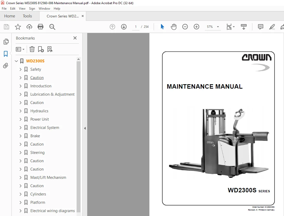
Crown Forklift WD2300S SERIES Maintenance Manual – PDF DOWNLOAD
$26.95
Crown Forklift WD2300S SERIES Maintenance Manual – PDF DOWNLOAD
Description
Crown Forklift WD2300S SERIES Maintenance Manual – PDF DOWNLOAD
FILE DETAILS:
Crown Forklift WD2300S SERIES Maintenance Manual – PDF DOWNLOAD
Language : English
Pages :254
Downloadable : Yes
File Type : PDF
TABLE OF CONTENTS:
Crown Forklift WD2300S SERIES Maintenance Manual – PDF DOWNLOAD
WD2300S 1
Safety 11
Symbols Used in the Manual 13
Caution 13
General Safety Instructions 14
Maintenance and Repair Instructions 14
Maintenance and Repair 14
Before Parking the Truck 15
Before Working on the Truck 15
Before Starting the Truck 15
Warning and Instruction Decals on the Truck 15
Introduction 17
Introduction 19
General 19
Operator manual 19
Service Training 19
Ordering Spare Parts 19
Using the Manual 20
Lubrication & Adjustment 21
Lifting the Truck 23
Lifting by Crane 23
Lifting with another Forklift Truck 23
Jacking up the Truck 24
Towing the Truck 25
Caution 25
Accessing the Components 26
Power unit cover 26
Control handle 26
Control handle knuckle 26
Mast 27
Platform and side restraint 27
Maintenance 29
Recommended Lubricants and Oils 29
Lubricants 29
Cold Store Trucks 29
Taking the truck out of service 29
Returning the Truck to Service 29
Inspection and Maintenance Schedule 31
Testing the Operation of the Safety Reverse Switch 35
Inspection and Maintenance Schedule 36
Lubrication Points 41
Drive Wheel and Castor Wheels 42
Setting the contact pressure 42
Torques 44
Hydraulics 47
Hydraulic Symbols 49
Hydraulic Unit Removal 53
Hydraulic System 54
Function 54
Lifting (Main Lift) 54
Lowering (Main Lift) 54
Lifting (Initial Lift) 54
Lowering (Initial Lift) 54
Hydraulic Reservoir Capacity 58
Changing the Hydraulic oil and Hydraulic Filter 58
Motor & Pump Assembly 60
Hydraulic lines and fittings 60
General Rules for Hydraulic Lines and Connections 60
Bleeding the Hydraulic System 61
Drift Test 61
Disassembly 61
Motor 62
Pump 62
Relief Valve 65
Replacing the relief valve 65
Relief valve setting 65
Relief valve test and setting 66
Testing and setting the load-sensing pressure switches 67
Setting the pressure switch points 68
Pressure switch PS1 68
Pressure switch PS2 68
Pressure switch PS3 68
Power Unit 69
Gear Unit 71
Preparatory Measures 71
Tools required: 71
Disassembly 71
Servicing 72
General 72
Gear Unit Disassembly / Assembly 74
Disassembly 74
Assembly 75
Preparing the gear unit 75
Assembling the flange shaft 75
Pinion Shaft Aassembly 76
Adjusting the Bevel Wheel Set 76
Checking the Flank Tooth Bearing 77
Final Assembly 77
Re-Assembly 78
Traction motor 78
Electrical System 79
Wire Colour Code 81
Abbreviations 82
Sundry Abbreviations 83
Electrical Wiring Diagrams 84
Electrical Components 86
Traction Pod (POT, FS, RS) 86
Fast / Slow Travel Switch (HSS) 86
Safety Reverse Switch (SAS) 86
Brake Switch (BRS) 86
Horn Switch (HNS1 & 2) 87
Key Switch (KYS) 87
Emergency Disconnect (BD) 87
Fuses (FU) 87
Thermo Switch (THS, optional) 87
Diode D4 87
Diode Block (DB) 87
Platform Logic (PLM) 87
Limit Switch (LMS1) 88
Limit Switch (LMS 2, only for masts > 1700mm) 88
Limit Switch (LMS3, only for masts > 1700mm) 88
Limit Switch LMS4 88
Pressure Switch (PS1) 88
Pressure Switch (PS2) 88
Pressure Switch (PS3) 88
Initial lift Switch 88
Hydraulic Control Module (HCM) 89
Raise / Lower Switches (RAS, LOS) 89
Control Handle Main PCB (Main PCB) 89
Hydraulic PCB (Hydr PCB) 89
Speed Transmitter PCB (R/T PCB) 89
Heating Option (F/C) 89
Battery 91
General 91
Replacing the Battery 91
Battery Discharge Indicator (BDI) 92
Operation 92
General 93
Battery Discharge Indicator Setting (BDI) 93
Calibration for Wet Batteries 94
Troubleshooting 95
Contactors 96
Inspection 96
Contacts 96
Coils 96
Springs 96
Servicing 97
Dismantling 97
Assembly 97
SEM1 Traction Controller 98
General 98
Precautionary Measures 98
Operating Characteristics 98
Speed control 98
Reduced Travel Speed Zones 99
Downhill Speed Control 99
Regenerative Braking 99
Anti Roll Down Function 99
Hourmeter 99
Self-Diagnostic System 99
Monitored Circuits100
Safety Mechanisms100
Incorrect polarity100
Wiring Errors100
Temperature protection100
Start sequence100
Protection rating100
Maintenance101
Replacing the SEM1 Traction Controller102
Parameter Setting after Replacing the Traction Controller103
Preparatory Measures103
Adjustment103
Status LED106
Travel Speed Test107
Programmer108
General108
SEM1 Traction Controller Operating Menu110
General110
Menu Functions110
PARAMETER CHANGE110
TEST110
ALARMS110
PROGRAM VACC110
CONFIG110
Menu Structure for Folding Platform111
Parameter Setting, Folding Platform112
TESTER Menu115
Max speed in relation to the reductionlevel116
ALARMS Menu117
Traction Pod120
Calibrating the Potentiometer, PROGRAM VACC Menu120
Preparatory Measures120
Calibration120
CONFIG Menu122
SET MODEL122
SET OPTIONS122
ADJUSTMENTS122
Traction Controller Safety Test123
WD2300S Platform Logic Box124
Platform Logic Controller, Part No 816050124
Checking the Platform Logic128
Hydraulic Control Module (HCM), Part No 816177129
Operation129
Calibrating the HCM131
Electric Motors132
General Maintenance Instructions132
Preparatory Measures132
Important Maintenance Instructions132
Traction Motor Maintenance133
Access to brushes133
Maintenance133
Armature134
Bearings134
Pump Motor Maintenance135
Access to brushes135
Maintenance135
Armature135
Brake137
Brake139
Dismantling140
Test and Inspection140
Assembly141
Caution141
Air Gap Setting142
Braking Torque Setting142
Brake Test143
Steering145
Control Handle Return Springs147
Caution147
Adjustment147
Disassembly147
Installation148
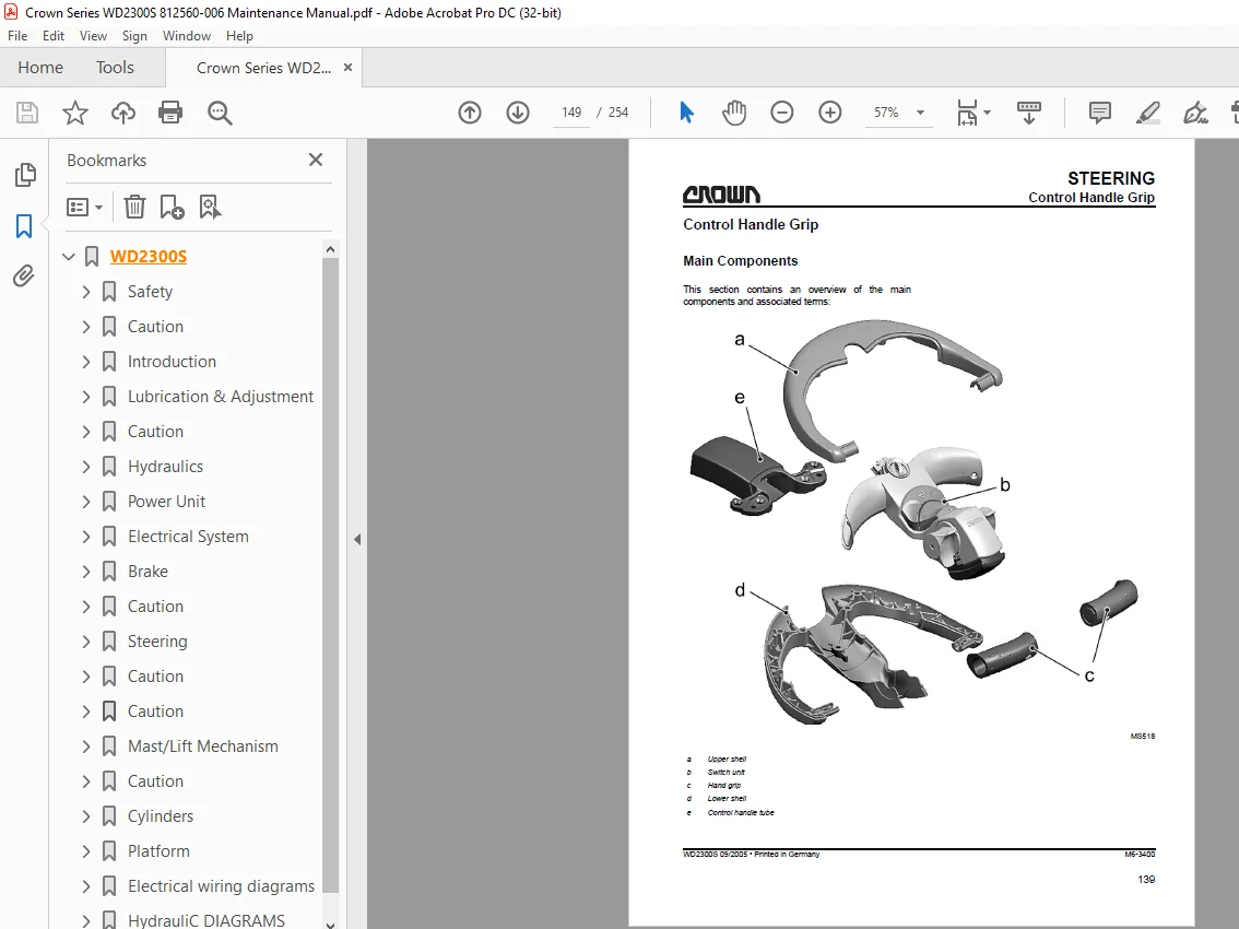
Control Handle Grip149
Main Components149
Control Handle Grip Components150
Caution150
Hand Grip Shells150
Upper and lower shell removal150
Upper and lower shell assembly152
Switch Unit152
Disassembly152
Switch unit assembly153
Disassembly154
Installation154
Hydraulic PC Board154
Disassembly154
Installation155
Main board removal/installation155
Potentiometer156
Disassembly156
Installation157
Safety Reverse Switch157
Disassembly157
Installation158
Horn Switch159
Disassembly159
Installation159
Hand Grip159
Disassembly159
Installation160
Initial Lift Switch160
Disassembly161
Installation161
Mast/Lift Mechanism163
Lift Linkage165
Adjusting the Fork Height165
Fork Adjustment166
Adjusting the fork height166
Mast168
General168
Torque Requirements168
Lifting Gear Minimum Capacity168
Mast Removal168
Caution168
Installation170
Fork Carriage Removal171
Fork Carriage Installation171
Fork Carriage Adjustment172
Mast Maintenance173
Lubricating Roller Tracks173
Mast Shims174
Lowering Plumb Test176
Preparatory Measures176
Carrying Out The Vertical Plumb Test176
Lift Limit Cutout / Initial Lift177
Lift Limit Cutout Setting177
LMS 2-4 Limit Switch Adjustment178
Lift Limit Cutout Setting178
Connecting the Lift Limit Switches180
Lift Chains181
General181
Inspection181
Cleaning182
Wear182
Freedom of Movement of Chain Links183
Chain Tension183
Chain Anchor and Pulleys183
Worn Connection Plates184
Protruding or Turned Chain Pins184
Corrosion185
Chain Lateral Wear185
Uneven Chain Tension185
Misaligned Lift Components185
Lift Chain Lubrication186
Separating Lift Chains187
Separation187
Fork Tines188
General188
Terms188
Fork Identification188
Repairs189
Fork Inspection189
Verticality Test190
Fork Blade Warping191
Measuring the Fork Tip Width191
Fork Tine Height Difference191
Fork Stop191
Fork Blade Wear192
Cylinders193
Cylinders195
General195
Safety when working on hydraulic systems195
General Instructions for Repairing Hydraulic Components195
General195
Plunger Cylinders196
Piston Cylinders198
Single-Acting Cylinder199
Double-Acting Cylinder199
Rod Seal Assembly200
General200
Large Rod Seal Assembly201
Small Seal Rod Assembly202
Rod Seal Assembly, Sealing Lip First203
Initial Lift Cylinder205
Operation205
Disassembly206
Inspection207
Replacing the rod seal207
Free Lift Cylinder208
Seal Replacement208
Installing Carriage Cylinder210
Cylinder Bleeding and Flushing211
Free lift cylinder bleeding211
Flushing – Mast Lift Cylinders and Free Lift Cylinders211
Drift Test211
Platform213
Mechanical Adjustment215
Platform Switch (PLS) Adjustment217
Platform Cushioning218
Layering the disk springs218
Side Restraint, Mechanical Adjustment219
Electrical wiring diagrams221
Standard Diagrams224
Overview224
Traffic Control Logic Circle226
Traffic Control Load Circle227
Hydraulic Traffic Modul and Diodes Block228
Power Unit Control Circle229
Control Handle Control Circle230
Platform & Mast Control Circle231
Platformmodul232
Option Wiring Diagrams234
Overview234
Traffic Control Logic Circle236
Traffic Control Load Circle237
Hydraulic Traffic Modul and Diodes Block238
Power Unit Control Circle239
Control Handle Traffic Circle240
Platform & Mast Traffic circle241
Platformmodul242
Power Cables244
Legend245
Main Wire Harness246
Folding platform, all versions246
Control Handle Wire Harness247
Horn Switch Wire Harness248
HydrauliC DIAGRAMS249
Hydraulic Diagrams252
IMAGES PREVIEW OF THE MANUAL:
S.M 5/24