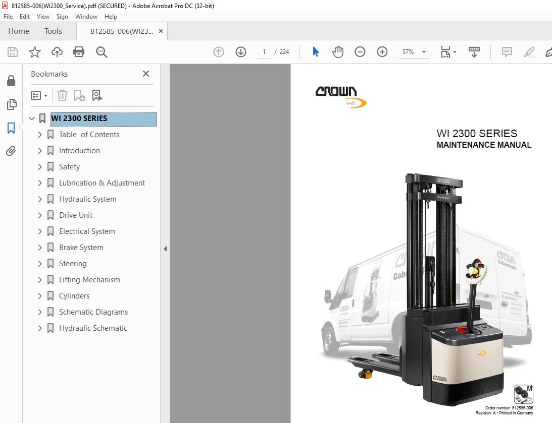
Crown Forklift WI 2300 Series Maintenance Manual 812585-006 PDF
$28.95
Crown Forklift WI 2300 Series Maintenance Manual 812585-006 – PDF DOWNLOAD
Description
Crown Forklift WI 2300 Series Maintenance Manual 812585-006 – PDF DOWNLOAD
FILE DETAILS:
Crown Forklift WI 2300 Series Maintenance Manual 812585-006 – PDF DOWNLOAD
Language : English
Pages :224
Downloadable : Yes
File Type : PDF
TABLE OF CONTENTS:
Crown Forklift WI 2300 Series Maintenance Manual 812585-006 – PDF DOWNLOAD
WI 2300 SERIES 1
Table of Contents 3
Introduction 1 5
Safety 5 5
Lubrication & Adjustment 11 5
Hydraulic System 37 6
Drive Unit 51 7
Electrical System 63 7
Brake System 103 10
Steering 111 10
Lifting Mechanism 127 11
Cylinders 153 12
Schematic Diagrams 179 13
Hydraulic Schematic 201 13
Introduction 15
Important Information 17
Manual structure 17
Text mark-ups in the manual 17
Service personnel qualification 17
Ordering Spare Parts 17
Ordering documentation 17
Safety 19
Safety Notices 21
Basic Safety Notices 22
Organisational measures 22
Personal safety equipment 22
Protecting the hazardous area 22
Hazards from stored energy 22
Repair work 22
Restoring the truck to service after repair work 23
Cleaning work 23
Handling batteries 23
Warning and instruction decals on the truck 23
Lifting gear and slings 23
Environmental protection 23
Lubrication & Adjustment 25
Transport and Storage 27
Lifting the Truck 27
Lifting the truck by crane 27
Lifting the truck with a forklift truck 28
Towing the Truck 29
Jacking up the Truck 30
Placing the Truck in Storage 31
Testing Trucks in Storage 31
Restoring the Truck to Service 31
Battery Maintenance 31
Component Access 32
Accessing the Motor Compartment 32
Motor compartment components 33
Accessing the Back of the Motor Compartment 34
Components on the back of the motor compartment 35
Accessing the Control Handle Components 35
Control handle components 35
Accessing the Distributor PCB 36
Recommended Lubricants and Consumables 37
Cold Store Truck Requirements 37
Abbreviations used in the Table 37
Planned Maintenance 39
Maintenance Schedule 39
Annual Inspection in Accordance with FEM 4004 39
Terms and Abbreviations used 39
Torques 44
Standard torques 44
Cleaning the Truck and Components 45
Effects of incorrect cleaning 45
Electrical components 45
Roller and slide bearings 45
Corrosion-protected surfaces 45
Environmental Protection 45
Cleaning the Entire Truck 45
Cleaning Removed Components 46
Cleaning lift chains 46
Cleaning other mechanical components 46
Replacing the Load and Castor Wheels 47
Replacing the Load Wheels 47
Removing the load wheels 47
Load wheel assembly 47
Replacing the Castor Wheel 47
Castor wheel removal 47
Castor wheel assembly 47
Lowering Plumb Test 47
Adjusting the position of the pivoting carriage 48
Replacing the Castor Wheel Suspension 49
Castor wheel suspension removal 49
Castor wheel suspension assembly 49
Hydraulic System 51
General Instructions 53
Hydraulic Lines and Ports 53
Bleeding the Hydraulic System 53
Drift Test 53
Lift Operation Test 53
Hydraulic Unit Components 53
Hydraulics manifold ports and valves 54
Hydraulic Diagram – TL Mast 55
Hydraulic Diagram – TT Mast 56
Hydraulic Diagram – TF Mast 57
Functional Description 58
Terminology Explanation 58
Main Lift, Raise 58
Main Lift, Lower 58
Initial Lift, Raise 58
Initial Lift, Lower 58
Initial Lift Lowering and Blocking 58
Repairing the Hydraulic Unit 59
Hydraulic Unit Removal 60
Hydraulic Unit Servicing 60
Hydraulic Unit Assembly 60
Replacing the Hydraulic Oil 61
Relief Valve Replacement and Adjustment 62
Relief Valve Disassembly 62
Relief Valve Assembly 62
Relief Valve Adjustment 62
Testing the Relief Valve 63
Hydraulic System Troubleshooting 64
Drive Unit 65
Drive Unit Components 67
Replacing the Drive Wheel 68
Drive Wheel Disassembly 68
Drive Wheel Assembly 68
Replacing the Drive Unit 69
Drive Unit Removal 69
Drive Unit Assembly 69
Replacing the Drive Gear Unit 70
Drive Gear Unit Removal 70
Drive Gear Unit Assembly 70
Repairing the Drive Gear Unit 71
Drive Gear Unit Disassembly 72
Drive Gear Unit Assembly 72
Adjusting the bevel gear set 73
Changing the Gear Oil 75
Draining the Oil 75
Adding Gear Oil 75
Repairing the Live Ring Bearing 76
Removing the Live Ring Bearing 76
Installing the Live Ring Bearing 76
Electrical System 77
Electrical Components 79
Brief Description 79
(ALM) Travel alarm 79
(ARB) Anti roll back module 79
(BBD) Battery connector 79
(BDI) Unigage 79
(BRK) Brake 79
(BRS) Brake switch 79
(EDS) Emergency Disconnect switch 79
(F/R Contactor) Direction contactor 79
(FU) Fuses 79
(HCM) Hydraulic control module 79
(HM) Horn 79
(HNS1 & HNS2) Horn switches 79
(HSS) “Rabbit/Turtle” toggle switch 79
(HYD PCB) Hydraulic printed circuit board 79
(ILS Lift & ILS Lower) Initial lift switches 79
(KYS) Key switch 80
(LMS – initial) Limit switch 80
(LMS – 1700 mm) Limit switch 80
(LOS1, LOS2) Lower switches 80
(MAIN PCB) Main circuit board 80
(ORS) Override switch 80
(PM / M2) Pump motor 80
(P) Pump contactor 80
(PCB) Distributor PCB 80
(POT, FS, RS) Traction pod 80
(PV) Proportional valve 80
(RAS) Raise switch 81
(SAS) Safety reverse switch 81
(THS) Thermal switch 81
(THS1) Motor thermal switch 81
(TM / M1) Traction motor 81
Electrical Component Assembly Location 82
Distributor PCB components 84
Traction Controller 1207 85
Key switch 85
Current limit 85
Overvoltage protection 85
Overtemperature protection 85
Performance reduction for low voltage 85
Fault identification 85
Error Logging 85
Traction Controller Operator Panel 86
Potentiometer Adjustment 86
Connecting the Programmer 86
Status LED Display 86
Status LED Display Overview 87
Troubleshooting 88
Traction Controller Servicing 89
Cleaning the Traction Controller 89
PMT Test 90
PMT Test Wiring Diagram 91
1307 Programmer 92
Operation 92
Connecting the Programmer 92
Key Function Description 93
SCROLL DISPLAY keys 93
CHANGE VALUE keys 93
MORE INFO key 93
PROGRAM key 93
TEST key 93
DIAGNOSTIC key 94
SPECIAL DIAGNOSTIC menu 94
Selecting the SPECIAL DIAGNOSTIC menu 94
SPECIAL PROGRAM Menu 94
Selecting the SPECIAL PROGRAM menu 94
1311 Programmer 95
Operation 95
Menus 96
Main menu 96
Programmer menu 96
Monitor menu 96
Fault menu 96
Functions 96
Adjusting the programmer 96
Menu Terms 97
PROGRAM Menu 97
TEST menu 97
DIAGNOSTICS and SPECIAL DIAGNOSTICS menus 98
SPECIAL PROGRAM menu 98
Traction Controller Settings 99
Replacing the Display Instrument100
Display Instrument Removal100
Display Instrument Assembly100
Battery Discharge Indicator (BDI) Information100
Lift cutout100
Battery Discharge Indicator (BDI) Adjustment101
Wet cell battery calibration101
Replacing the Key Switch (KYS)102
Key Switch Removal102
Key Switch Assembly102
Replacing the LMS-Initial Limit Switch103
Limit Switch Removal103
Limit Switch Assembly103
Replacing the LMS-1700 mm Limit Switch104
Limit Switch Removal104
Limit Switch Assembly104
Replacing the Override Switch (ORS) and the Brake Switch (BRS)105
Override Switch Assembly105
Replacing the Brake Switch105
Replacing the Emergency Disconnect Switch (EDS)106
Emergency Disconnect Switch Removal106
Emergency Disconnect Switch Assembly106
General Motor Maintenance Instructions107
Brushes107
Motor107
Armature107
Repairing the Traction Motor108
Traction Motor Removal and Disassembly109
Checking the Traction Motor Components for Wear109
Traction Motor Assembly109
Repairing the Pump Motor110
Pump Motor Removal and Disassembly110
Checking the Pump Motor Components for Wear110
Pump Motor Assembly110
Repairing the Direction Contactor (F/R)111
Direction Contactor Removal111
Direction Contactor Disassembly111
Wear Test112
Checking contacts112
Checking the coils112
Checking the springs112
Direction Contactor Assembly112
Direction Contactor Assembly112
Repairing the Pump Contactor113
Pump Contactor Removal113
Pump Contactor Disassembly113
Wear Test114
Checking the contacts114
Checking the coils114
Checking the springs114
Pump Contactor Assembly114
Pump Contact Assembly114
Battery Information115
Charging the Battery115
Replacing the Battery115
Hydraulic System Calibration116
Brake System117
General Brake Information119
Electromagnetic Brake Operating Principle119
Repairing the Brake120
Brake Removal120
Brake Disassembly121
Brake Assembly121
Brake Installation121
Brake Air Gap Adjustment122
Adjusting the Air Gap122
Setting the Braking Distance123
Checking the Braking Distance124
Reducing the Stopping Distance124
Steering125
Repairing Control Handle Return Springs127
Panel Removal127
Return Spring Pre-Tension Adjustment127
Replacing the Return Springs128
Return spring removal128
Return spring assembly128
Tools required:128
Repairing the Steering Column129
Steering Column Removal129
Steering Column Assembly130
Replacing the Steering Chain131
Steering Chain Removal131
Steering Chain Assembly131
Adjusting the Control Handle132
Repairing the Control Handle133
Replacing the Control Handle Shells134
Shell removal134
Shell assembly135
Replacing the Switch Unit135
Switch unit removal136
Switch unit assembly136
Replacing the “Rabbit/Turtle” Toggle Module136
Toggle module removal136
Toggle module assembly136
Replacing the Control Handle Grip PC Boards137
Hydraulic PC board removal137
Hydraulic PC board assembly137
Main PC board removal137
Main PC board assembly137
Replacing the Traction Potentiometer137
Traction potentiometer removal138
Traction potentiometer assembly139
Replacing the Safety Reverse Switch (SAS)139
Safety reverse switch (SAS) removal139
Safety reverse switch (SAS) assembly140
Replacing the Grips and Horn Switch140
Replacing the Initial Lift Switch140
Initial lift switch removal140
Initial lift switch assembly140
Lifting Mechanism141
Repairing the Mast143
TT Mast143
TF Mast143
TL Mast143
Repairing the TT Mast144
Replacing the Mast Rollers146
Mast Roller Removal146
Replacing the Mast Rollers and Adjusting the Slack151
Assembling the Remaining Attachments and Mast Unit152
Preparing the Hydraulic System153
Lowering Plumb Test154
Repairing the Fork Carriage156
Replacing the Fork Carriage Rollers156
Checking the Fork Carriage157
Chain Supports and Lift Chains158
General158
Periodic inspection of chain supports and lift chains158
Periodic replacement of chain supports and lift chains158
Cleaning lift chains158
Inspecting Chain Supports and Lift Chains159
Checking the service hours for the lift chains and anchor bolts159
Checking the lift chain for elongation159
General159
Preparatory measures159
Freedom of movement160
Worn or missing plates160
Turned pins161
Corrosion161
Chain lateral wear161
Checking chain supports and anchor bolts161
Checking the chain pulleys162
Checking and adjusting the chain tension162
Checking the lifting components for misalignment162
Lubricating Lift Chains163
General information163
Lubrication intervals and lubricants163
Separating Lift Chains164
Tools and equipment required164
Lift Height Adjustment165
Outrigger Lift Height Adjustment165
Fork Height Adjustment165
Cylinders167
General169
Safety Notices169
Hydraulic System Repair Instructions169
Tools170
Small hook170
Extractor170
Producing extractors170
Groove aligning arbor for small rod seals170
Assembly devices for large rod seals171
Protective mechanisms171
Rod Seal Removal and Assembly172
Removing a large rod seal172
Removing a small rod seal172
Inserting a large rod seal172
Fitting a small rod seal173
Rod seal assembly, sealing lip first173
Replacing the Lift Cylinders174
Replacing the Outer Lift Cylinders on the TL and TT Masts174
Outer lift cylinder removal175
Outer lift cylinder assembly176
Replacing the Outer Lift Cylinders on TF Masts177
Outer lift cylinder removal177
Outer lift cylinder assembly177
Replacing the Free Lift Cylinders on the TT and TF Masts178
Free Lift Cylinder Removal178
Free lift cylinder assembly179
Replacing the Initial Lift Cylinder180
Initial lift cylinder removal180
Initial lift cylinder assembly180
Repairing Lift Cylinders181
Checking Cylinders Before Starting Repair Work181
Replacing the Rod Seals181
Repairing the Lift Cylinders on the TL and TT Masts182
Lift Cylinder Disassembly183
Lift Cylinder Assembly183
Repairing the Lift Cylinder on the TF Mast184
Lift Cylinder Disassembly185
Lift Cylinder Assembly185
Repairing the Free Lift Cylinders on the TF and TT Masts186
Free Lift Cylinder Disassembly187
Free Lift Cylinder Assembly187
Repairing the Initial Lift Cylinder188
Initial Lift Cylinder Disassembly189
Initial Lift Cylinder Assembly189
Bleeding and Flushing the System190
Bleeding the Lift Cylinders190
Bleeding the Free Lift Cylinder190
Flushing the Lift and Free Lift Cylinders190
Drift Test191
Schematic Diagrams193
Electrical Diagram195
Distributor PCB196
Traction Controller – Drive Side197
Brake Circuit198
Instrument & HCM Circuit199
Control Handle Control Circuit200
Lift Limit Switches and Temperature Switches201
Anti Roll Back (ARB)202
Main Harness203
Plug connector housing204
Contact pins204
Cable lugs and rings204
Limit Switch Cables (LMS)207
Plug connector housing207
Contact pins207
Horn Wire Harness208
Plug Connector Housing208
Contact Pins208
Control Handle and Horn Switch Assembly209
Replacement Parts209
Control Handle, Sideshift/Initial Lift Assembly210
Control Handle Wire Harness211
Plug Connector Housing211
Contact pins212
Strobe and Alarm Signal Wire Harness213
Plug Connector Housing213
Contact pins213
Cable Lugs and Rings213
Power Cables214
Hydraulic Schematic215
Hydraulic Symbols217
Hydraulic Diagram – TL Mast221
Hydraulic Diagram – TT Mast222
Hydraulic Diagram – TF Mast223
IMAGES PREVIEW OF THE MANUAL:
S.M 5/24