Crown Forklift WP2300S Series Maintenance Manual 812529-006 pdf
$26.95
Crown Forklift WP2300S Series Maintenance Manual 812529-006 – PDF DOWNLOAD
Description
Crown Forklift WP2300S Series Maintenance Manual 812529-006 – PDF DOWNLOAD
FILE DETAILS:
Crown Forklift WP2300S Series Maintenance Manual 812529-006 – PDF DOWNLOAD
Language : English
Pages :196
Downloadable : Yes
File Type : PDF
TABLE OF CONTENTS:
Crown Forklift WP2300S Series Maintenance Manual 812529-006 – PDF DOWNLOAD
WP2300S 1
REVISION 3
TABLE OF CONTENT 7
Table of Content 1 7
Table of Content 2 8
Table of Content 3 9
Table of Content 4 10
Table of Content 5 11
Table of Content 6 12
SAFETY 15
Safety Symbols used in the Manual 15
General Maintenance and Repair Safety Notes 15
Maintenance and Repair 15
Before Leaving the Truck 16
Before Carrying out Work on the Truck 16
Before Operating the Truck 16
Warnings and Labels on the Truck 16
INTRODUCTION 19
General 19
Operating Instructions 19
Service Training 19
Ordering Spare Parts 19
Using the Manual 19
Model-Number 20
LUBRICATION AND ADJUSTMENT 23
Jacking up the Truck 23
Raising the Truck with a Crane 23
Fixed Platform 23
Folding Platform 24
Both Platforms 25
Raising with a Forklift Truck 26
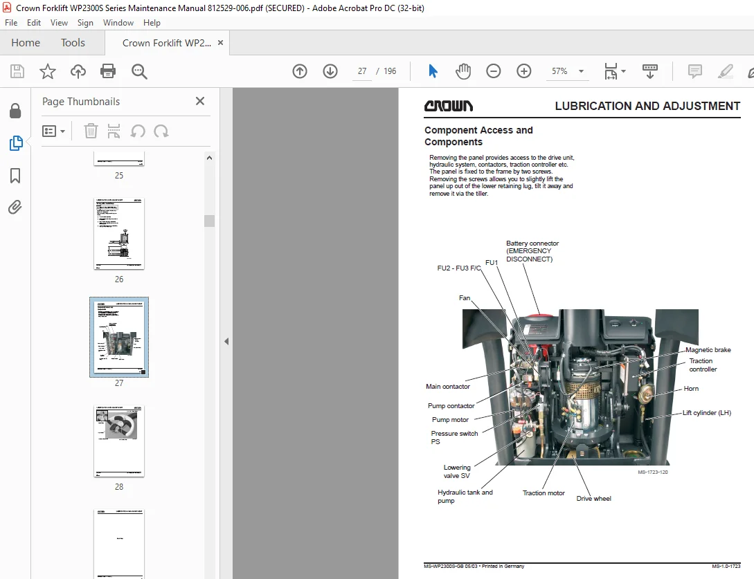
Component Access and Components 27
Maintenance 30
Recommended Lubricants and Oils 30
Lubricants 30
Cold Store Trucks 30
Truck Decommissioning 30
Restoring the Truck to Service 30
Lubricant Type, Product Description, Manufacturer, Crown Part No, Type 31
Product, Product Name, Application, Crown Part No 31
Check and Maintenance Schedule 32
Daily or every 8 service hours 32
Safety Reverse Switch – Functional Test 34
Monthly or every 100 service hours 36
Every 3 months or 250 service hours 38
Every 6 months or 500 service hours 38
Annually or every 1000 service hours 40
Every 2 years or 2000 service hours 40
Grease items and grease intervals 42
Adjusting the Contact Pressure of the Castors and the Drive Wheel 44
Procedure: 44
Calculating the Adjustment Required: 44
Example: 44
Torques 45
Screw grade marking Nut grade marking 45
Standard Screws and Nuts 46
Umbrako Screws and Nuts 46
HYDRAULICS 49
Hydraulic Symbols 49
Hydraulic Symbols 1 49
Hydraulic Symbols 2 50
Hydraulic Symbols 3 51
Hydraulic Symbols 4 52
Hydraulic System 53
Operation 53
Removing the Hydraulic Unit 54
Replacing the Hydraulic Pump 55
Removal 55
Installation 55
Commissioning and Bleeding the System 55
Pump Motor 57
Filters 57
Replacing the Pressure Filter 57
Replacing the Suction and Return Filters 57
Oil Change 57
Replacing the Safety Valve 58
Safety Valve Setting 58
Safety Valve Test and Setting 58
Testing and Setting the Load-Dependent Pressure Switch 59
DRIVE UNIT 63
Gear Unit 63
Preparatory Measures 63
Required Tools: 63
Removal 63
Maintenance 63
General 63
Gear Unit Disassembly / Assembly 65
Disassembly 65
Assembly 65
Preparing the Gear Unit 65
Flange Shaft Assembly 65
Pinion Shaft Assembly 66
Adjusting the Bevel Gear Assembly 66
Basic Rules: 66
Checking the Flank Tooth Bearing 66
Final Assembly 66
Assembly 67
Drive Motor 67
ELECTRICS 71
Electrics – General 71
Wire Colour Codes 71
Abbreviations 72
Switch Symbol Abbreviation List 72
Sundry Abbreviations 73
Other Abbreviations 74
Electrical Symbols 74
Electrical Components 75
Travel Switch (POT, FS, RS) 75
Fast/Slow Switch (HSS) 75
Safety Reverse Switch (SAS) 75
Brake Switch (BRS) 75
Brake Switch (BRS) Used from serial no 5A336576, except for 5A337937 75
Raise/Lower Switch (RAS, LOS) 76
Pressure Switch (PS) 76
Platform Control Switches (GCSR, GCSL, PLS) 76
Lift Limit Switch (LMS) 76
Horn Switch (HNS) 76
Foot Switch (FTS) 76
Key Switch (KYS) 76
Emergency Disconnect (BD) 76
Fuses (FU) 76
Thermal Switch (THS) 76
Filter (WP2340S only) 76
Diode D4 76
Diode block (DB) 76
Platform Logic (PLM) Used from serial no 5A336576, except for 5A337937 77
WP2330S 78
WP2330S PLM Used from serial no 5A336576, except for 5A337937 79
WP2335S 80
WP2340S 81
Battery 83
General 83
Replacing the battery 83
Battery Discharge Indicator (BDI) 83
General 83
Battery Discharge Indicator Setting (BDI) 84
Calibration 84
Discharge Terminal Voltage Setting in Volts/Cell 84
SEM1 Traction Controller 85
General 85
Precautionary Measures 85
Operational Features 85
Speed Control 85
Reduced Speed Ranges 85
Downhill Speed Control 85
Regenerative Braking 85
Anti – Roll Down Function 85
Hourmeter 86
Self Test 86
Monitored Circuits 86
Protective Devices 86
Polarity Protection 86
Wiring Errors 86
Temperature 86
Start Sequence 86
Safety Class 86
Maintenance 87
Replacing the SEM1 Traction Controller 88
Parameter Setting after Replacing the Traction Controller 88
Preparatory Measures 88
Setting 88
Status LED 90
Programmer 91
General 91
Description of Keys 92
Operating SEM1 Controller Menu 92
General 92
Menu Functions 92
PARAMETER CHANGE 92
TEST 92
ALARMS 92
PROGRAM VACC 92
CONFIG 92
Menu Structure for Folded Platform 93
Menu Structure for Fixed Platform 94
Parameter Setting, Folded Platform 95
Parameter Change Menu, folded Platform, SW#006B 95
Parameter Change Menu, folded Platform, SW#006B 96
Parameter Setting, for Trucks with a Folded Platform, 02 Rev 05/05 97
Parameter Change Menu, folded Platform, SW#006B 97
Parameter Setting, Fixed Platform 96
Parameter Change Menu, fixed Platform, SW#105 96
Parameter Setting, for Trucks with a Fixed Platform, 02 Rev 05/05 97
Parameter Change Menu, fixed Platform, SW#105 97
Parameter Change Menu, fixed Platform, SW#105 99
TESTER Menu100
ALARMS Menu101
ALARMS Menu 101
ALARMS Menu (Contd)102
ALARMS Menu (Contd)103
Calibrating the Traction Pod Potentiometer, PROGRAM VACC menu104
Preparatory Measures104
Calibration104
CONFIG Menu105
SET MODEL105
SET OPTIONS105
ADJUSTMENTS105
Traction Controller Safety Test106
Troubleshooting107
Platform LogicController PN 815144107
WP2300S Platform Logic Box, M502107
Electric Motors109
General Maintenance Instructions109
Preparation109
Important Maintenance Instructions109
Traction Motor Maintenance110
Access to Brushes110
Maintenance110
Armature110
Bearings110
Pump Motor Maintenance111
Access to brushes111
Maintenance111
Armature111
BRAKE115
Brake115
Removal115
Disassembly116
Test and Inspection116
Assembly116
Assembly117
Air Gap Setting117
Brake Moment Setting118
Testing the Brakes118
WP2300S Nominal Breaking Distances and Screw Depth118
STEERING121
Multitask Handle – Springs for Return Function121
Adjustment121
Removal121
Assembly121
Control Handle Grip123
Main Components123
Hand grip component removal and assembly124
Hand Grip Shells124
Upper and lower shell removal124
Upper and lower shell assembly125
Switch Unit126
Disassembly126
Switch unit assembly126
“Rabbit/Turtle” toggle switch127
Disassembly127
Assembly127
Hydraulic PC board127
Disassembly127
Assembly127
Main PC Board Removal/Installation129
Potentiometer130
Disassembly130
Assembly130
Safety Reverse Switch131
Disassembly131
Assembly131
Horn switch132
Disassembly132
Assembly132
Hand Grip133
Disassembly133
Assembly133
LIFTING MECHANISM137
Lift Linkage137
Fork Height Setting137
Lift Limit Cutout139
Lift Limit Cutout Setting139
CYLINDERS143
Lift Cylinders143
Operation143
Removal143
Inspection145
Replacing the Piston Seal145
PLATFORM149
Folding Platform149
Mechanical Setting149
Platform Switch Setting (PLS)150
Platform Suspension151
Plate Spring Layers151
Side Gates, Mechanical Setting152
Fixed Platform WP2335S153
Replacing the Safety Switch153
Fixed Platform WP2340S154
Replacing the Safety Switch154
Fixed Platform WP2340S155
Replacing Switches below the Entry Bars (FPS 1 & FPS 2)155
ELECTRICAL DIAGRAMS157
WP2330S160
Notes to overall wiring diagram, standard version, folded platform, WP2330S160
Overall Wiring Diagram, Standard, Folded Platform, WP2330S161
SCHEMATIC DIAGRAM162
TRACTION CONTROLLER – SEM1 LOGIC CIRCUIT162
TRACTION CONTROLLER – SEM1 POWER CIRCUIT163
PLATFORM CIRCUIT163
POWER UNIT CIRCUIT164
CONTROL HANDLE CIRCUIT164
PLATFORM LOGIC165
Notes to overall wiring diagram, standard version, fixed platform WP2330S166
Overall Wiring Diagram, Folded Platform with Options WP2330S167
WP2330S OPTIONS, FOLDED PLATFORM SCHEMATIC DIAGRAM168
WP2330S STANDARD, FOLDED PLATFORM TRACTION CONTROLLER – SEM1 LOGIC CIRCUIT168
WP2330S STANDARD, FOLDED PLATFORM, TRACTION CONTROLLER – SEM1 LOGIC CIRCUIT169
WP2330S STANDARD, FOLDED PLATFORM, PLATFORM CIRCUIT169
WP2330S OPTIONS, FOLDED PLATFORM, POWER UNIT CIRCUIT170
WP2330S STANDARD, FOLDED PLATFORM, CONTROL HANDLE CIRCUIT170
WP2330S STANDARD, FOLDED PLATFORM, PLATFORM LOGIC171
WP2335S172
Notes to overall wiring diagram, Standard Version, Fixed platform WP2335S172
Overall Wiring Diagram, Standard, Fixed Platform WP2335S173
Notes to overall wiring diagram, with options, fixed platform, WP2335S174
Overall Wiring Diagram, Fixed Platform with Options WP2335S175
WP 2340S176
WP 2340S STANDARD, FIXED PLATFORM SCHEMATIC DIAGRAM176
WP 2340S STANDARD, TRACTION CONTROLLER – SEM1 LOGIC CIRCUIT176
WP 2340S STANDARD, POWER CIRCUIT – TRACTION & PUMP MOTOR177
WP 2340S STANDARD, FIXED PLATFORM, PLATFORM CIRCUIT177
WP 2340S STANDARD, FIXED PLATFORM, POWER UNIT CIRCUIT178
WP 2340S STANDARD, FIXED PLATFORM, CONTROL HANDLE CIRCUIT178
WP 2340S OPTIONS, FIXED PLATFORM, SCHEMATIC DIAGRAM179
WP 2340S OPTIONS, FIXED PLATFORM, TRACTION CONTROLLER – SEM1 LOGIC CIRCUIT179
WP 2340S OPTIONS, FIXED PLATFORM, POWER CIRCUIT – TRACTION & PUMP MOTOR180
WP 2340S OPTIONS, FIXED PLATFORM, PLATFORM CIRCUIT180
WP 2340S OPTIONS, FIXED PLATFORM, POWER UNIT CIRCUIT181
WP 2340S OPTIONS, FIXED PLATFORM, CONTROL HANDLE CIRCUIT181
Wire harness overview, folded platform, WP2330S all versions182
Main Harness, Folded Platform, WP2330S, All Versions183
Control Handle – Wire Harness, Folded Platform, WP2330S, All Versions184
Horn Switch – Wire Harness, Folded Platform, WP2330S, All Versions 185
Wire Harness Overview, Fixed platform, All versions186
Wire Harness Overview, Fixed Platform, WP2340S, All Versions187
Control Handle – Wire Harness, Fixed Platform, WP2340S, All Versions188
Horn Switch – Wire Harness, Fixed Platform, WP2340S, All Versions189
Cables, Platform, Fixed Platform, WP2340S, All Versions190
Power Cables191
HYDRAULIC CIRCUIT195
IMAGES PREVIEW OF THE MANUAL:
S.M 5/24