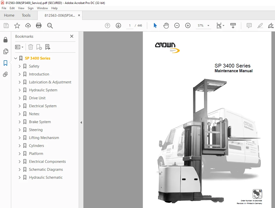
Crown SP3400 Series Maintenance Manual – PDF DOWNLOAD
$29.95
Crown SP3400 Series Maintenance Manual – PDF DOWNLOAD
Description
Crown SP3400 Series Maintenance Manual – PDF DOWNLOAD
FILE DETAILS:
Crown SP3400 Series Maintenance Manual – PDF DOWNLOAD
Language : English
Pages :446
Downloadable : Yes
File Type : PDF
TABLE OF CONTENTS:
Crown SP3400 Series Maintenance Manual – PDF DOWNLOAD
SP 3400 Series 1
Safety 19
Symbols Used in the Manual 21
Safety Symbols 21
General Symbols 21
Fork direction 21
General Safety Instructions 22
Maintenance and Repair Instructions 22
Maintenance and Repair 22
Before Parking the Truck 22
Before Working on the Truck 22
Before Starting the Truck 23
Warning and Instruction Decals on the Truck 23
Control of Hazardous Energy 25
Battery 25
Safety Rules 25
Battery Removal 26
Battery Installation 26
Lockout – Tagout 26
Brake 27
Capacitance 28
Hydraulic System 28
Depressurising the hydraulic system 28
Accumulator 29
Lifting and Blocking 30
Required tools 30
Raising the Side 30
Raising the Drive Wheel 31
Blocking Masts 32
Cleaning Methods 33
Introduction 35
General 37
Operating Instructions 37
Service Training 37
Ordering Spare Parts 37
Using the Manual 38
Data Plate 38
Model Number 39
* Capacity 39
** Performance Key 39
Truck Data Number 40
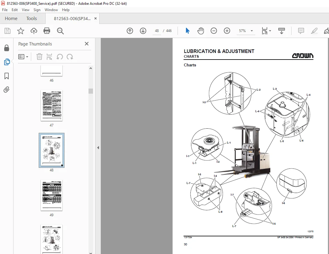
Lubrication & Adjustment 43
General 45
Charts 48
Componentry 58
Accumulator 58
ALM1 Status Alarm 58
BRES1, BRES2 (Option) Battery Restraint Switch 58
BRK1 Brake 58
BRS1 Brake Switch 58
CHS1, CHS2 Chain Slack Switches (TT Mast Only) 60
CHS3, CHS4 Chain Slack Switches 60
CV1 Check Valve (only 3427 / 3422) 60
CV2 Check Valve 60
CV3 Check Valve 60
Cylinder Free Lift (TT Mast Only) 60
Cylinder Mast 60
DCM Display Module 62
DPS Display Switch 62
DTS1 Drive / Tow Switch 62
ECR1 Steering Command Encoder 62
ECR2 Steering Feedback Encoder 62
ECR3 Traction Speed Encoder 62
ECR4 Lift Height Sensor 62
ED1 Emergency Disconnect Main Contactor 64
ED2 Emergency Disconnect Traction & Steering Contactor 64
EDS Emergency Disconnect Switch 64
Fan Operator Fan 64
FILTER Return 64
FNS Fan Switch 64
FS Forward Switch 64
FU1 Lights and Fan Fuse 66
FU2 Control Fuse 66
FU3 Options Fuse 66
FU4 Manual Brake Fuse 66
FU5 Brake Outer Coil Fuse 66
FU6 Brake Inner Coil Fuse 66
FU8 Pump Motor 1 Fuse 66
FU9 Pump Motor 2 Fuse 66
FU10 Steer Module Fuse 68
FU11 Freezer Condition Power Unit Fuse 68
FU12 Freezer Condition Platform Fuse 68
FU13 Traction Motor Fuse 68
GCM Guidance Control Module 68
GTS1, GTS2, GTS3, GTS4 Side Gate Switches 68
GTS5, GTS6 (SAA Only – not shown) Rear Gate Switches 68
GUS Guidance Switch 68
HN1 Horn 70
HN2 Back-Up or Travel Alarm 70
HNS1 Horn Switch 70
HSLCS High Speed Lower Cutout Switch 70
HSRCS High Speed Raise Cutout Switch 70
HTS24 610 mm (24 in) Height Limit Switch 72
HTS60 1525 mm (60 in) Height Limit Switch 72
HTS120 3050 mm (120 in) Height Limit Switch 72
HTS150 3810 mm (150 in) Height Limit Switch 72
HTS180 4570 mm (180 in) Height Limit Switch 74
K1 Power Up Relay 74
K2 Module Power 74
K5 Steer Motor Relay 74
K11 Freezer Condition Relay 74
K12 Freezer Condition Relay 74
KYS Key Switch 76
LCS1 Lower Cutout Switch 76
LGS1 Dome Light Switch 76
LGS2 Work Light Switch 76
LGS3 Spot Light Switch 76
LGT1 Strobe or Flashing Light 76
LGT2, 5 Work Lights 76
LGT3, 6 Dome Lights 78
LGT4, 7 Spot Lights 78
LOS1 Low Speed Lower Switch 78
LOS2 High Speed Lower Switch 78
M1 Traction Motor 78
M2 Power Steering Motor 78
M3 Lift Pump Motor 78
M4 Lift Pump Motor 78
MRC1 Traction Module 80
MVL Manual Valve Lowering 80
ORS1 Override Switch 80
P1 Low Speed Lift Pump Contactor 80
P1 PUMP Low Speed Lift Pump 80
P2 High Speed Lift Pump Contactor 80
P2 PUMP High Speed Lift Pump 80
POT1 Traction Request Potentiometer 82
PS1 Light Power Supply 82
PS2 Light Power Supply 82
PVL Proportional Lowering Valve 82
RAS1 Low Speed Raise Switch 82
RAS2 High Speed Raise Switch 82
RCS1, RCS2 Raise Cutout Switches 82
RES1 Resistor 84
RES2, RES3 Freezer Condition Heater 84
RES4, RES5 Freezer Condition Heater 84
RES6, RES7 Freezer Condition Heater 84
RES8, RES9 Freezer Condition Heater 84
RES10 Freezer Condition Heater 84
RES11 Freezer Condition Heater 84
RES12 Freezer Condition Heater 86
RES13 Freezer Condition Heater 86
RES14 Freezer Condition Heater 86
RES15, RES19 Freezer Condition Heater 86
RES16 Freezer Condition Heater 86
RES17 Freezer Condition Heater 86
RES18 Freezer Condition Heater 86
RES20, RES21 Freezer Condition Heater 88
RES30 Freezer Condition Heater 88
RES31 Freezer Condition Heater 88
RES32 Freezer Condition Heater 88
Reservoir 88
RGS1, RGS2 Rail Guide Switches 88
RS Reverse Switch 88
RV1 Relief Valve 88
SB10 Suppressor Block 90
SB11 Suppressor Block 90
SB21 Suppressor Block 90
SB30 Suppressor Block 90
SCM Steering Control Module 90
Sensor Bar Load Wheel Wire Guidance 92
Sensor Bar Steer Wheel Wire Guidance 92
Strainer Suction 92
Test Port 92
THS2 Power Unit Thermostat 92
THS3 Platform Thermostat 92
ZSS Zone Select Switch 92
Skids 94
Torque Values 95
Hydraulic System 97
Hydraulic Symbols 99
General103
Hydraulic Circuits104
Lift Circuit – One Speed Lift104
Relief Valve Operation104
Accumulator Operation104
Lift Circuit – Two Speed Lift105
Low Speed Lift105
High Speed Lift105
Relief Valve Operation105
Accumulator Operation105
Lower Circuit – One Speed/Two Speed Lower106
Lower106
Manual Lower Circuits108
Lift Circuit – One Speed Lift111
Lifting Fork Lift Circuit111
Relief Valve Operation111
Accumulator Operation111
Lift Circuit – Two Speed Lift W/Lifting Forks114
Low Speed Lift114
High Speed Lift114
Relief Valve Operation114
Accumulator Operation114
Lower Circuit – One Speed/Two Speed Lower117
Lower117
Manual Lower Circuits120
Reservoir121
Hydraulic Lines and Fittings121
Filter122
Drift Test122
Lift Drift Test122
Freezer Preparation123
Hydraulic Pump124
Pump – Gear124
Oil Seal Removal124
Oil Seal Replacement125
Pump Disassembly125
Parts Inspection125
Body125
Gears126
Mounting Flange126
Pump Reassembly127
Lift/Lower Control Valve130
Relief Valve- RV1 Operation130
Adjustment (125 Trucks)130
Relief Valve- RV1 & RV2 Operation131
Adjustment (10 Trucks)131
Accumulator133
Precharging133
Maintenance136
Hydraulics Troubleshooting Chart136
Drive Unit139
Drive Tire Replacement141
Drive Unit Lubrication142
Oil Pump Disassembly (Refer to Illustrations 1895 & 13131)142
Oil Pump Assembly (Refer to Illustrations 1895 & 13131)143
Drive Unit Removal & Installation (Refer to Illustration 3272)144
Electrical System145
Encoders147
Electrical Wiring149
Wiring Color Codes149
Color149
Number149
Power Cables150
Symbols151
Basic Symbols152
Motor Monitoring System (MMS)154
Overtemperature Sensors155
Brushwear Sensors155
Event Codes157
General157
Some Troubleshooting Basics157
Check the Event Code Listing157
No Event Code?157
To Locate Malfunctioning Components157
Test Points157
Event Codes157
Event Code 201158
Event Code 202159
Event Code 204160
Event Code 208161
Event Code 209163
Event Code 210164
Event Code 211165
Event Code 212166
Event Code 213167
Event Code 215168
Event Code 216170
Event Code 217172
Event Code 218173
Event Code 219174
Event Code 221175
Event Code 222175
Event Code 223176
Event Code 224177
Event Code 227178
Event Code 228179
Event Code 311179
Event Code 312179
Event Code 313180
Event Code 314180
Event Code 315181
Event Code 316182
Event Code 317183
Event Code 318184
Event Code 319185
Event Code 321186
Event Code 322187
Event Code 323188
Event Code 324189
Event Code 326190
Event Code 327190
Event Code 328191
Event Code 331192
Event Code 332194
Event Code 333195
Event Code 334196
Event Code 335197
Event Code 336197
Event Code 337198
Event Code 339199
Event Code 341199
Event Code 342200
Event Code 343200
Event Code 344201
Event Code 345202
Event Code 346203
Event Code 347204
Event Code 348205
Event Code 349206
Event Code 351207
Event Code 352208
Event Code 353209
Event Code 354210
Event Code 355210
Event Code 356210
Event Code 357211
Event Code 358211
Event Code 362211
Event Code 363212
Event Code 364213
Event Code 365214
Event Code 366214
Event Code 367215
Event Code 368215
Event Code 369215
Event Code 371216
Event Code 372216
Event Code 373216
Event Code 374217
Event Code 375217
Event Code 376217
Event Code 377218
Event Code 378218
Event Code 379219
Event Code 381219
Event Code 382219
Event Code 383220
Event Code 384221
Event Code 385222
Event Code 386222
Event Code 387222
Event Code 388223
Event Code 391223
Event Code 392223
Event Code 393223
Event Code 394224
Event Code 396225
Event Code 397226
Event Code 398226
Event Code 399226
Event Code 411226
Event Code 412226
Event Code 413226
Event Code 414227
Event Code 415227
Event Code 416227
Event Code 417227
Event Code 418227
Event Code 419228
Event Code 421229
Event Code 422232
Event Code 423234
Event Code 424236
Event Code 425237
Event Code 426239
Event Code 427239
Event Code 428241
Event Code 429243
Event Code 431243
Event Code 432243
Event Code 433243
Event Code 434244
Event Code 435244
Event Code 436244
Event Code 437244
Event Code 438245
Event Code 439245
Event Code 441247
Event Code 442249
If: Fault persists Then replace GCM250
Event Code 800250
Event Code 801250
Event Code 802251
Event Code 803252
Event Code 804253
Event Code 805253
Event Code 806254
Event Code 807255
Event Code 808256
Event Code 809257
Event Code 810258
Event Code 811258
Event Code 812259
Event Code 813259
Event Code 814259
Event Code 827260
Event Code 828261
Event Code 829262
Event Code 831264
Event Code 832266
Event Code 833267
Event Code 834267
Event Code 835267
Event Code 836267
Event Code 837268
Event Code 838268
Tune Up269
Service Terminal269
Description269
Service Terminal Operation270
Keyboard Commands270
Calibration272
Truck Setup Menus273
Lift Cutouts or Zone Menus274
Truck Option Menus275
PM Interval Setup Menus276
Hourmeter Reset Menus277
Wire Guidance Calibration Menus278
Traction Setups/Calibration Menus279
Traction Setups/Features Menus280
Features/Travel Alarm Menus281
Traction Setups/Performance Menus282
Traction Setups/Performance Menus (cont’d)283
System Information Menus288
View Enable Config Menus289
Truck Monitors Menus / View Encoder Counts Menu290
View Switch Status Menus / View System Constants Menus291
View Hardware Outputs Menus293
View Hourmeter Data Menus / View Wire Guide Sensors Menus294
Traction Analyzer Menus295
Status Analyzer Menus296
Traction Inputs Menus297
View Switches Menu298
Traction Outputs Menus299
Wire Guidance System300
Operation Modes301
Manual301
Automatic301
Sensors303
Calibration303
Troubleshooting304
Guidance Module (GCM)305
Pin assignment305
Line Driver Output307
Sensor Bearing309
Checking Truck Steering System310
Truck Steering System Components311
Contactors313
Inspection313
Contacts313
Coil313
Component Replacement314
Contact Replacement314
Coil Replacement314
Steering Feedback315
Gear Assembly315
45-7534320
45-7534318
Control Module317
General317
Access317
Troubleshooting318
Adjustment318
Acceleration Potentiometer (POT1)s318
Directional Switches (FS & RS)319
Component Replacement320
FS and RS320
Actuator Arm320
Potentiometer (POT1)321
Cam Torsion Spring, Stop322
Twist Grip323
RAS1, RAS2, LOS1, LOS2, HNS, EDS324
Button Return Springs324
Buttons324
Power Disconnect Button Springs325
Notes:326
45-7534322
45-7534324
Battery327
Safety Rules327
Checking328
Battery Care328
Charging329
Placing battery on charge:330
Removing battery from charge:330
Battery Stop Adjustment330
Battery Removal331
Battery Installation332
Battery Cleaning333
Trouble Shooting333
Motors334
Brake System337
General339
Braking Force339
Brake Force Adjustment339
BRAKE ADJUSTMENT340
Air Gap Adjustment340
Torque Gap Adjustment341
Rotor and Brake Pad Replacement343
Brake Assembly344
Steering347
System Description349
Steering Direction349
Steering Wheel Direction Indicator349
Steering Wheel Adjustment350
Steering Motor Gearbox351
Lifting Mechanism353
Lift Chains355
Inspection355
Cleaning355
Wear355
Freedom of Movement of Chain Links357
Chain Tension357
Chain Anchor and Pulleys357
Worn Connection Plates357
Protruding or Turned Chain Pins358
Corrosion358
Chain Lateral Wear358
Uneven Chain Tension359
Misaligned Lift Components359
Lift Chain Lubrication359
Separating Lift Chains361
Tools and Equipment Required361
Separation361
FEM / ISO Forks363
General363
Terms363
Fork Identification363
FEM / ISO Fork Inspection364
Repair364
Inspection Intervals364
Crack Inspection364
Fork Blade Warping364
Fork Tip Straightness Test365
Measuring the Fork Tip Height365
Fork Tine Height Difference365
Fork Stop366
Fork Blade Abrasion Check366
Platform Fork Blades367
Fork Inspection367
Fork Blade Abrasion Check367
Overloading369
Bent or Twisted Forks369
Hanger370
Cylinders371
Safety373
For your personal protection:373
General Instructions for Repairing Hydraulic Components373
Rod Seal Assembly374
General374
Large Rod Seal Assembly374
Small Seal Rod Assembly375
Rod Seal Assembly, Sealing Lip First376
Maintenance377
Mast, Free Lift and Auxiliary Fork Cylinders377
Inspection378
Disassembly379
Accessing Rod Packing- Mast Cylinder379
Accessing Rod Packing – Free Lift Cylinder380
Accessing Rod Packing- Auxiliary Fork Cylinder380
Rod Packing Replacement380
Mast Cylinder Removal382
Auxiliary Fork Cylinder Removal383
Free Lift Cylinder Removal383
Free Lift, Mast and Auxiliary Fork Cylinder Assembly384
Free Lift, Mast and Auxiliary Fork Cylinder Installation384
Platform385
Safety Shield Installation387
Floor Mat Replacement388
Forks388
Fork Inspection388
Fork Replacement389
Removal389
Installation389
Pallet Grab (Option)390
Release Handle Adjustment390
Pedal Adjustment390
Pallet Grab Removal391
Operator Compartment Gates393
Spring Replacement394
Removal394
Installation394
Operator Egress System395
Platform Removal & Shimming395
Basics395
Platform Removal and Shimming, TL Mast396
Shimming396
Removing the Platform for Shimming396
Correct Method Shimming Method398
Incorrect Shimming Method398
Installing the Platform398
Platform Removal & Shimming TT Mast399
Removing the Platform for Shimming400
Correct Method Shimming Method401
Incorrect Shimming Method401
Installing the Platform401
Electrical Components403
Index405
Schematic Diagrams415
Block Diagram417
Schematic, Standard418
Schematic with Options419
Platform, Standard420
Platform, Auxiliary Fork Lift421
Distribution Panel422
Traction, Standard423
Traction, Auxiliary Fork Lift424
Display Module (DCM)425
Traction Module (MRC1)426
Steering Module (SCM)427
Traction Control428
Guidance Control Module (GCM)429
Lights, Fan, Power Supply430
Freezer Condition431
Power Cables432
Order Information433
Wire Harness434
Platform434
Power Unit434
Power Unit436
Platform437
Platform with Auxiliary Lift Fork438
Hydraulic Schematic439
Single Speed Lift441
Two Speed Lift442
Single Speed Lift With Lifting Forks443
Two Speed Lift With Lifting Forks444
TL Mast445
TT Mast446
IMAGES PREVIEW OF THE MANUAL:
S.M 5/24