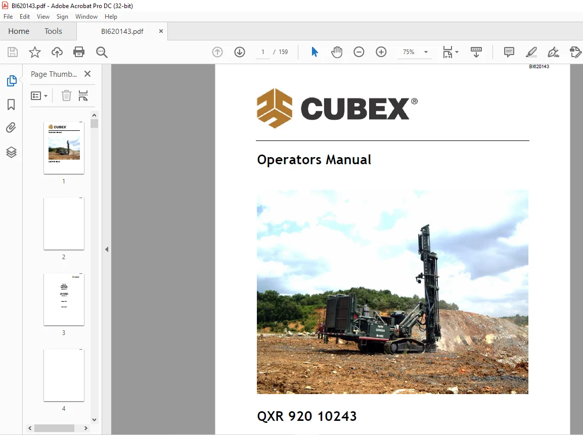
CUBEX QXR 920 10243 Operator Manual BI620143 – PDF DOWNLOAD
$27.95
CUBEX QXR 920 10243 Operator Manual BI620143 – PDF DOWNLOAD
Description
CUBEX QXR 920 10243 Operator Manual BI620143 – PDF DOWNLOAD
FILE DETAILS:
CUBEX QXR 920 10243 Operator Manual BI620143 – PDF DOWNLOAD
Language : English
Pages : 159
Downloadable : Yes
File Type : PDF
IMAGES PREVIEW OF THE MANUAL:
DESCRIPTION:
CUBEX QXR 920 10243 Operator Manual BI620143 – PDF DOWNLOAD
Introduction:
1.1 Drill Description:
- The Cubex Megamatic QXR series of drills are designed to deliver maximum drilling efficiency and
flexibility using a Down-the-hole Hammer. The standard QXR is a QXR 920 with a 900 cfm/500 psi
(25.7m3/min 34.5 bar) compressor, a mast with carousel capable of handling 20 ft. (6 m) drill pipe
and a Caterpillar engine. The QXR series of drills also offers up to 1350 cfm/500 psi (38.6 m3/34.5
bar) air capacity. - The QXR is designed to drill up to 8” (203 mm) diameter holes to a depth of 140 feet (42.7 m)
without adding drill pipe to the carousel.
1.2 Manual Objectives:
This manual covers a description and the operation of the Cubex QXR drill and can be used as a
training aid for Cubex’s Operator Training Course.
The Objective of this manual is to familiarize operators with the following:
• Major components and sub-assemblies of drill
• Layout of controls and what they operate
• Drilling
• Maintenance
• Operator Safety
• Troubleshooting
TABLE OF CONTENTS:
CUBEX QXR 920 10243 Operator Manual BI620143 – PDF DOWNLOAD
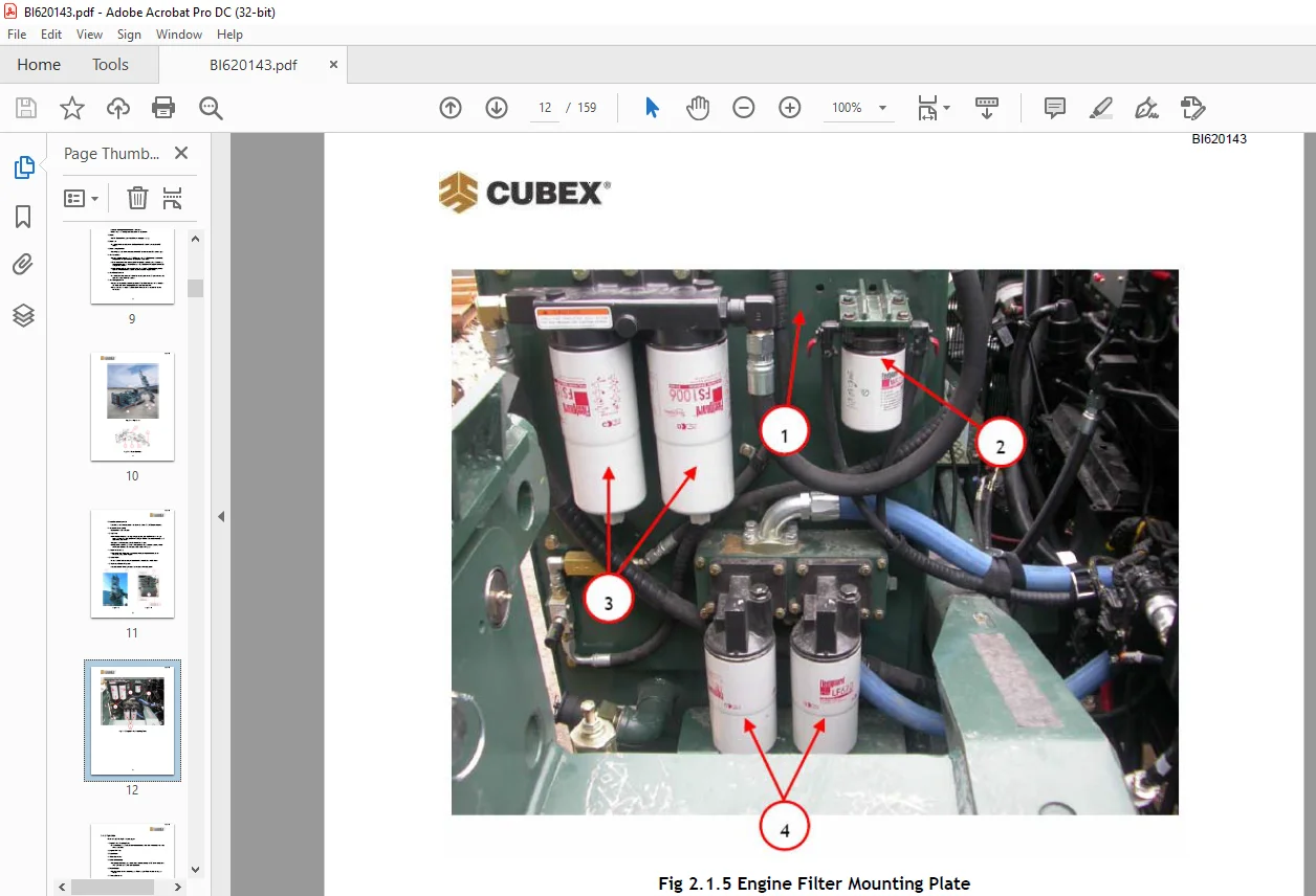
Section 1   Introduction....................................................................  7
	1.1 Drill Description...................................................................  7
	1.2 Manual Objectives...................................................................  7
	1.3 Drill Orientation...................................................................  8
Section 2   Description of Equipment........................................................  9
	2.1 Major Components and Sub-assemblies.................................................  9
		2.1.1 Mast and Undercarriage........................................................  9
		2.1.2 Right Side.................................................................... 13
		2.1.3 Left Side..................................................................... 17
		2.1.4 Front......................................................................... 23
		2.1.5 Rear.......................................................................... 25
		2.1.6 Fire Suppression (Optional)................................................... 27
			Section A –Operators Cab........................................................ 28
			Section B – Rear of Unit........................................................ 29
			Section C –Front of Unit........................................................ 30
			Section D – Cab Boom............................................................ 31
	2.2 Electrical Controls................................................................. 32
		2.2.1 Joysticks..................................................................... 33
		2.2.2 Engine Control Panel (Inside Cab)............................................. 35
	2.3 Manual Hydraulic Controls........................................................... 37
		2.3.1 Set-Up, Drilling, and Tramming Valve Bank..................................... 37
		2.3.2 Carousel and Drilling Valve Bank.............................................. 39
	2.4 Display Screens..................................................................... 41
		2.4.1 System Screen................................................................. 41
		2.4.2 Status Bar.................................................................... 41
		2.4.3 Menu Buttons.................................................................. 43
		2.4.4 Status Indicator.............................................................. 43
		2.4.5 Configuration Menu............................................................ 44
			Tram Settings................................................................... 45
			Make-up / Breakout.............................................................. 46
			Weight on Bit................................................................... 47
			Hour Meter...................................................................... 48
			Accra-Feed Configuration Screen................................................. 49
		Lube/Grease/Water Configuration..................................................... 50
		Preset Configuration - Setting Hole Depth........................................... 51
		Tramming and Oscillation............................................................ 52
		Setup Screen – Layer 1.............................................................. 53
		Setup Screen – Layer 2.............................................................. 54
		Setup Screen – Layer 3.............................................................. 55
		Drill Screen – Layer 1.............................................................. 56
		Drill Screen – Layer2............................................................... 57
		Drill Screen – Layer 3.............................................................. 58
		Accra-Feed Screen – Layer 1......................................................... 59
		Drill Screen – Manual Drilling Layer 1.............................................. 60
Section 3   Start-Up and Tramming........................................................... 61
	3.1 Operating Procedures for Start-Up................................................... 61
		3.1.1 Pre-start Inspection.......................................................... 61
		QXR Operator Pre-Start Checklist.................................................... 63
	3.2 Start-Up............................................................................ 65
		3.2.1 Inside Cab.................................................................... 65
		3.2.2 Outside Cab................................................................... 65
	3.3 Tramming............................................................................ 66
		3.3.1 Tramming from the Tram Station................................................ 66
		3.3.2 Tramming from the Cab......................................................... 66
	3.4 Set Up.............................................................................. 69
		3.4.1 Set-Up from the Cab........................................................... 69
		3.5 Indexing the Swing Cylinder..................................................... 73
Section 4   Drilling........................................................................ 75
	4.1 Drilling Procedures................................................................. 75
		4.1.1 Hammer Installation Procedure................................................. 79
		4.1.2 Drill Pipe Installation (Adding Rods)......................................... 80
		4.1.3 Drill Pipe Removal............................................................ 84
	4.2 Delivery Systems.................................................................... 89
		4.2.1 Water Injection Procedure..................................................... 89
		4.2.2 Grease Injection Procedure.................................................... 89
		4.2.3 Oil Injection Procedure....................................................... 90
	4.3 Drilling............................................................................ 91
		4.3.1 Manual Drilling............................................................... 91
		4.3.2 Drilling with Accra-Feed Feature (Optional)................................... 95
Section 5   Maintenance..................................................................... 97
	5.1 Daily Maintenance Procedures........................................................ 97
		REMEMBER............................................................................ 98
		Fluid Notices....................................................................... 98
	5.2 Lubrication.........................................................................100
		5.2.1 Rock Drill Grease.............................................................100
		5.2.2 Lubrication Points and Intervals..............................................100
		5.2.3 Centralized Machine Lubrication...............................................101
		5.2.6 Undercarriage Lubrication and Inspection......................................103
	5.3 Safety Procedures...................................................................104
		5.3.1 Personal Protection Equipment.................................................104
		5.3.2 Overhead and Buried Utilities.................................................104
		5.3.3 Ask for Assistance............................................................105
		5.3.4 Safety Shutdowns..............................................................105
			5.3.4.1 Functionality...........................................................106
			5.3.4.2 Operator Checks and Maintenance.........................................106
			5.3.4.3 Safety Shutdown – Tension Adjustment Procedure..........................107
		5.3.5 Safety Procedures and Labels..................................................109
Section 6 Troubleshooting...................................................................115
	6.1 Troubleshooting the Tram Drive......................................................115
		Crawler Does Not Run But Tramming Motors Are Operating..............................115
		Crawler Does Not Move and Tramming Motor Does Not Run...............................115
		Crawler Does Not Tram Straight......................................................115
	6.2 Troubleshooting the Hydraulic System................................................116
		Pump Does Not Deliver Oil...........................................................116
		Pump is Running Hot.................................................................116
		Cavitation or Pump Noise............................................................116
		Insufficient Pressure...............................................................116
		Slow Rotation at Top Drive..........................................................116
		No Rotation at Top Drive Assembly...................................................116
		Slow or No Feed.....................................................................117
		Mast Does Not Rotate................................................................117
		Actuator Allows Mast to Move After Being Set........................................117
	6.3 Troubleshooting the Water Injection Pump............................................118
		Discharge Pressure is Too Low.......................................................118
		Cavitation Problems.................................................................118
		No Water Discharge..................................................................118
		Excessive Pump Noise................................................................118
	6.4 Troubleshooting the Air Driven Oil Injection Pump...................................119
		Air Motor Does Not Operate..........................................................119
		Air Seepage From Air Exhaust While Pump is Not Working..............................119
		Loss of Pressure, Volume, or Continuous Operation of Pump when Not in Normal Use....119
		Excessive Amount of Air in Lubricant or Excessive Amount of Lubricant in Air........119
	6.5 Troubleshooting the Air Driven Grease Injection.....................................119
		Air Motor Does Not Operate..........................................................119
		Grease Is Not Delivered to the Drilling Air Line....................................119
	6.6 Troubleshooting the Air Delivery System.............................................120
		Air Pressure Builds too Slowly......................................................120
		Compressor Shuts Down with Air Demand Present.......................................120
		Compressor Does Not Build-Up Full Discharge Pressure................................120
		Compressor Unloading with an Excessive Pressure Build-Up............................120
		Excessive Compressor Fluid Consumption..............................................120
		Compressor Overheating..............................................................121
	6.7 Troubleshooting the Hammer..........................................................122
		Tool Does Not Start.................................................................122
		Tool Stops Operating................................................................122
		Operating Pressure is Lower than Specifications.....................................122
		Low Penetration Rate................................................................122
		Galling of Internal Parts...........................................................122
	6.8 Troubleshooting the Drill Bit.......................................................123
		Abrasive Wear.......................................................................123
		Loss of Carbides in Bit.............................................................123
		Bit Breakage and Carbide Failure....................................................123
		Carbide Breakage....................................................................123
		Uneven Wear Conditions..............................................................124
	6.9 Troubleshooting Depth Laser.........................................................125
		Laser appears not working. No red light is coming out of aperture. .................125
		Laser appears working, red light is pulsing in even intervals, no output signal.....125
		Laser appears working, red light is pulsing but in un-even intervals................126
		General notes:......................................................................126
Cubex Terra DGS Operation Manual............................................................127
Section 1   Introduction....................................................................131
	1.1 Features............................................................................131
Section 2 Software Removal and Installation.................................................132
	2.1 Removal / Installation Procedure:...................................................132
	2.2 Sensor Installation.................................................................139
		2.2.1 Installing Wires in Sensor Box................................................140
		2.2.2 Screen Installation...........................................................148
Section 3 Operation.........................................................................149
	3.1 ZERO-OFFSET Calibration Procedure...................................................156
	3.2 Local and Absolute Heading Measurements.............................................159
Need help? Contact: [email protected]
https://vimeo.com/865259610?share=copy
PLEASE NOTE:
- This is the SAME exact manual used by your dealers to fix your vehicle.
- The same can be yours in the next 2-3 mins as you will be directed to the download page immediately after paying for the manual.
- Any queries / doubts regarding your purchase, please feel free to contact [email protected]
S.V