Daewoo Doosan DL450-5 Shop Manual Serial Number 10001 and Up – PDF DOWNLOAD
Original price was: $90.00.$29.95Current price is: $29.95.
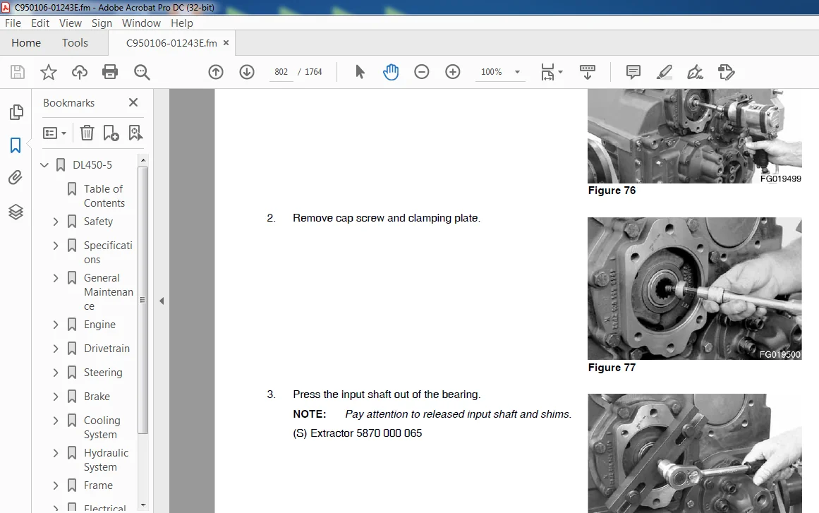
Daewoo Doosan DL450-5 Shop Manual Serial Number 10001 and Up – PDF DOWNLOAD
Description
Daewoo Doosan DL450-5 Shop Manual Serial Number 10001 and Up – PDF DOWNLOAD
DESCRIPTION:
Daewoo Doosan DL450-5 Shop Manual Serial Number 10001 and Up – PDF DOWNLOAD
GENERAL
Safe Operation is Operator’s Responsibility Only trained and authorized personnel should operate and maintain the machine. Follow all safety rules, regulations and instructions when operating or performing maintenance on machine.
• Do not operate machine if you are under the influence of drugs or alcohol. An operator who is taking prescription drugs must get medical advice to determine if he or she can safely operate the machine.
• When working with other personnel on a work site, be sure that all personnel know the nature of work and understand all hand signals that are to be used.
• Be sure that all guards and shields are installed in their proper location. Have guards and shields repaired or replaced immediately if damaged.
• Be sure that you understand the use and maintenance of all safety features such as pilot cutoff switch and seat belt. Use them always.
• Never remove, modify or disable any safety features. Always keep them in good operating condition.
• Always check for and know the location of underground and overhead utility lines before working.
• Failure to use and maintain safety features according to instructions in this manual, Safety Manual and Shop Manual can result in death or serious injury
Know Your Machine
Know how to operate your machine. Know the purpose of all controls, gauges, signals, indicators and monitor displays. Know the rated load capacity, speed range, braking and steering characteristics, turning radius and operating clearances. Keep in mind that rain, snow, ice, loose gravel, soft ground, slopes, etc., can change operating capabilities of your machine.
Proper Work Tools and Attachments
- Only use work tools and attachments that are recommended by DOOSAN for use on DOOSAN machines. When installing and using optional attachments, read instruction manual for attachment, and general information related to attachments in this manual. Because DOOSAN cannot anticipate, identify or test all attachments that owners may want to install on their machines, contact DOOSAN for written authorization and approval of attachments, and their compatibility with optional kits.
- Attachments and attachment control systems that are compatible with the machine are required for safe and reliable machine operation. Do not exceed maximum operating weight (machine weight plus attachment) that is listed on ROPS certification plate.
- Make sure that all guards and shields are in place on machine and on work tool. Depending on type or combination of work equipment, there is a potential that work equipment could interfere with the cabin or other parts of machine. Before using unfamiliar work equipment, check if there is any potential for interference, and operate with caution.
- While you are performing any maintenance, testing, or adjustments to attachments, stay clear of the following areas: cutting edges, pinch points, and crushing surfaces. Never use attachment as a work platform or manlift. Contact your DOOSAN distributor about auxiliary hydraulic kits for attachments installation. If you are in doubt about the compatibility of a particular attachment with the machine, consult your DOOSAN distributor.
Pressurized Fluids
- Pressurized air or fluids can cause debris and/or fluids to be blown out. This could result in death or serious injury. Immediately after operation is stopped, coolant, engine oil, and hydraulic oil are at their highest temperatures and the radiator and hydraulic tank are still under pressure. Always wait for temperature to cool down. Follow specified procedures when attempting to remove caps, drain oil or coolant, or replacing filters.
- Always wait for temperature to cool down, and follow specified procedures when performing these operations. Failure to do so can result in death or serious injury. When pressurized air and/or pressurized water is used for cleaning, wear protective clothing, protective shoes, and eye protection. Eye protection includes goggles or a protective face shield.
- Pressure can be trapped in a hydraulic system and must be relieved before maintenance is started. Releasing trapped pressure can cause sudden machine movement or attachment movement. Use caution if you disconnect hydraulic lines or fittings. High-pressure oil that is released can cause a hose to whip or oil to spray. Fluid penetration can result in death or serious injury.
- If fluid enters skin or eyes, get immediate medical attention from a physician familiar with this injury. Obey all local laws and regulations for disposal of liquids. To prevent hot coolant from spraying out, stop engine and wait for coolant to cool. Using gloves, slowly loosen cap to relieve pressure.
TABLE OF CONTENTS:
Daewoo Doosan DL450-5 Shop Manual Serial Number 10001 and Up – PDF DOWNLOAD
DL450-5…………………………………………………………………………………. 0
Table of Contents…………………………………………………………………….. 7
Safety………………………………………………………………………………. 9
Wheel Loader Safety……………………………………………………………….. 11
Safety Instructions……………………………………………………………. 15
Safety Messages……………………………………………………………….. 15
General………………………………………………………………………. 17
Safe Operation is Operator’s Responsibility…………………………………… 17
Know Your Machine………………………………………………………….. 17
Proper Work Tools and Attachments……………………………………………. 17
Pressurized Fluids…………………………………………………………. 18
Flying or Falling Objects…………………………………………………… 19
Personal Protective Equipment (PPE)………………………………………….. 19
Correction of Machine Problems………………………………………………. 20
Crushing and Cutting……………………………………………………….. 20
Hot Coolant and Oils – Burn Prevention……………………………………….. 21
Fire and Explosion Prevention……………………………………………….. 21
Fire Extinguisher and First-Aid Kit (Emergency Medical Kit)…………………….. 25
Electrical System and Electrical Shock……………………………………….. 25
Roll-over Protective Structure (ROPS)/ Falling Object Protective Structure (FOPS)…. 26
Operation…………………………………………………………………….. 28
Before Engine Starting……………………………………………………… 28
Work Site…………………………………………………………………. 28
Check Tire Pressure and Condition……………………………………………. 29
Mounting/Dismounting……………………………………………………….. 29
Cleaning………………………………………………………………….. 30
Operator Station…………………………………………………………… 30
Seat Belt…………………………………………………………………. 31
Visibility Information……………………………………………………… 32
Boost Starting or Charging Engine Batteries…………………………………… 33
Starting Engine……………………………………………………………. 34
Traveling…………………………………………………………………. 34
Lifting and Digging………………………………………………………… 36
Digging Beneath Overhangs…………………………………………………… 36
Digging Beneath Wheel Loader………………………………………………… 36
Operation on Slopes………………………………………………………… 37
Attachment………………………………………………………………… 38
Equipment Lowering with Engine Stopped……………………………………….. 38
Preventing Risk of Injuries or Death From Boom and Bucket………………………. 38
Engine Stop……………………………………………………………….. 40
Parking Machine……………………………………………………………. 40
Maintenance…………………………………………………………………… 41
Warning Tag……………………………………………………………….. 43
Cleaning………………………………………………………………….. 44
Proper Tools and Clothing…………………………………………………… 44
Disassembling Precautions…………………………………………………… 44
Use of Lighting……………………………………………………………. 45
Fire and Explosion Prevention……………………………………………….. 45
Burn Prevention……………………………………………………………. 46
Rubber That Contains Fluorides………………………………………………. 47
Rubber and Plastics………………………………………………………… 48
Welding Repairs……………………………………………………………. 49
Working on Machine…………………………………………………………. 50
Lock Inspection Covers……………………………………………………… 51
Accumulator……………………………………………………………….. 51
Compressed Air…………………………………………………………….. 51
Supports and Blocking for Work Equipment……………………………………… 52
High-pressure Lines, Tubes and Hoses…………………………………………. 52
Battery…………………………………………………………………… 53
Preservation/Storing Machine………………………………………………… 54
Transportation………………………………………………………………… 56
Obey State and Local Over-the-Road Laws and Regulations………………………… 56
Loading and Unloading………………………………………………………. 56
Transporting Machine……………………………………………………….. 57
Environment and Circumstances…………………………………………………… 58
Work Site Areas Requiring Extra Caution………………………………………. 58
High-voltage Cables………………………………………………………… 60
Underground Operation………………………………………………………. 60
Working in Water…………………………………………………………… 61
Working in Contaminated Environment………………………………………….. 61
Operation in Extreme Conditions……………………………………………… 62
Exhaust Ventilation………………………………………………………… 66
Asbestos Information……………………………………………………….. 66
Silica Dust Information…………………………………………………….. 67
Disposal of Hazardous Materials……………………………………………… 67
Sound…………………………………………………………………….. 67
Vibration Information………………………………………………………. 68
Specifications……………………………………………………………………….. 71
Specification…………………………………………………………………….. 73
Safety Instructions……………………………………………………………. 77
General………………………………………………………………………. 77
Component Locations……………………………………………………………. 78
Working Range and Dimensions……………………………………………………. 82
Working Capacities…………………………………………………………….. 84
Bucket Capacity……………………………………………………………. 84
Stability Data (EN – and ISO – Norms)………………………………………… 84
General Specifications…………………………………………………………. 85
Performance Tests……………………………………………………………… 86
Purpose of Performance Tests………………………………………………… 86
Kinds of Tests…………………………………………………………….. 86
Performance Standards………………………………………………………. 86
Precautions for Evaluation of Test Data………………………………………. 86
Definition of “Performance Standard”…………………………………………. 86
Preparation for Performance Tests……………………………………………….. 87
The Machine……………………………………………………………….. 87
Test Area…………………………………………………………………. 87
Precautions……………………………………………………………….. 87
Make Precise Measurement……………………………………………………. 87
Operational Performance Standard Table…………………………………………… 88
Operational Performance Test……………………………………………………. 90
Engine Speed………………………………………………………………. 90
Front Speed……………………………………………………………….. 92
Natural Subsidence of Cylinder………………………………………………. 93
Travel Speed – Acceleration and Deceleration………………………………….. 94
Steering Time……………………………………………………………… 95
Pressure Set………………………………………………………………. 96
Approximate Weight of Workload Materials…………………………………………. 98
Material Weight……………………………………………………………. 98
General Maintenance…………………………………………………………………… 101
General Maintenance Instructions.pdf………………………………………………… 103
Safety Instructions……………………………………………………………. 107
Welding Precautions and Instructions…………………………………………….. 108
Hydraulic System – General Precautions…………………………………………… 109
Maintenance Service and Repair Procedure…………………………………………. 111
General Precautions………………………………………………………… 111
Hydraulic System Cleanliness and Oil Leaks……………………………………….. 112
Maintenance Precautions for Hydraulic System Service…………………………… 112
Oil Leakage Precautions…………………………………………………….. 113
Cleaning and Inspection………………………………………………………… 114
General Instructions……………………………………………………….. 114
Bearing Inspection…………………………………………………………. 115
Standard Torques………………………………………………………………….. 123
Safety Instructions……………………………………………………………. 127
Torque Values for Standard Metric Fasteners………………………………………. 128
Torque Values for Standard U.S. Fasteners………………………………………… 129
Type 8 Phosphate Coated Hardware………………………………………………… 131
Torque Values for Hose Clamps…………………………………………………… 132
ORFS Swivel Nut Recommended Torque………………………………………………. 132
Torque Values for Split Flanges…………………………………………………. 133
Torque Wrench Extension Tools…………………………………………………… 134
Torque Multiplication………………………………………………………. 134
Other Uses for Torque Wrench Extension Tools………………………………….. 135
Tightening Torque Specifications (Metric)…………………………………….. 136
Engine………………………………………………………………………………. 139
Engine…………………………………………………………………………… 141
Safety Instructions……………………………………………………………. 147
Overview……………………………………………………………………… 148
Inspection……………………………………………………………………. 149
Cleaning the Engine………………………………………………………… 149
Special Tools…………………………………………………………………. 149
Mounting the Engine in a Universal Stand……………………………………… 159
Engine Identification………………………………………………………….. 160
Engine Data Plate………………………………………………………….. 160
Engine Specification…………………………………………………………… 161
Engine Performance Curves………………………………………………………. 162
Tightening Torques…………………………………………………………….. 164
Normal Tightening Torque……………………………………………………. 164
Special Tightening Torque…………………………………………………… 168
Cylinder……………………………………………………………………… 194
Cylinder Head……………………………………………………………… 194
Valve Mechanism……………………………………………………………. 212
Cylinder Block…………………………………………………………….. 216
Cylinder Liner…………………………………………………………….. 230
Flywheel Housing…………………………………………………………… 237
Front Cover……………………………………………………………….. 240
Oil Mist Separator…………………………………………………………. 242
Actuating System………………………………………………………………. 248
Camshaft………………………………………………………………….. 248
Connecting Rod…………………………………………………………….. 255
Crankshaft………………………………………………………………… 258
Flywheel………………………………………………………………….. 267
Piston……………………………………………………………………. 272
Roller Tappet……………………………………………………………… 278
Intake Manifold……………………………………………………………. 279
Torsion Damper…………………………………………………………….. 280
Belt Circuit………………………………………………………………. 281
Timing Gear……………………………………………………………….. 287
Lubrication System…………………………………………………………….. 293
General Information………………………………………………………… 293
Centrifugal Oil Cleaner…………………………………………………….. 295
Oil Cooler………………………………………………………………… 300
Oil Filter………………………………………………………………… 303
Oil Pump………………………………………………………………….. 304
Oil Sump………………………………………………………………….. 306
Oil Pressure Sensor………………………………………………………… 308
Troubleshooting Chips Found in the Engine…………………………………….. 309
Troubleshooting the Lubrication System……………………………………….. 313
Lubrication Oil Consumption…………………………………………………. 314
Exhaust System………………………………………………………………… 317
General Information………………………………………………………… 317
T113, Exhaust Temperature Sensor Before Catalytic Converter…………………….. 333
T115, NOx Sensor…………………………………………………………… 334
T131 NOx Sensor……………………………………………………………. 336
T116, Reductant Pick-up Unit………………………………………………… 338
Evaporator………………………………………………………………… 343
V117 Reductant Doser……………………………………………………….. 344
V118, Coolant Valve for Heating the Reductant System…………………………… 349
V183 Reductant Pump………………………………………………………… 351
H25, H26 Electrically Heated Reductant Hose…………………………………… 362
M4000 Electric Exhaust Brake………………………………………………… 364
Reductant Tank…………………………………………………………….. 370
Oxidation Catalytic Converter……………………………………………….. 377
Exhaust Manifold…………………………………………………………… 379
Variable Geometry Turbocharger………………………………………………. 385
EGR System………………………………………………………………… 393
EGR Valve…………………………………………………………………. 400
EGR Cooler………………………………………………………………… 405
Cooling System………………………………………………………………… 407
Internal Cleaning of Cooling System………………………………………….. 410
Charge Air Cooler………………………………………………………….. 411
Charge Air Temperature Sensor……………………………………………….. 413
Charge Air Pressure Sensor………………………………………………….. 415
Thermostat………………………………………………………………… 416
Coolant Pump………………………………………………………………. 419
Coolant Temperature Sensor………………………………………………….. 420
Fuel System…………………………………………………………………… 422
General Information………………………………………………………… 422
Accumulator……………………………………………………………….. 428
Fuel Manifold……………………………………………………………… 429
Overflow Valve…………………………………………………………….. 436
Feed Pump…………………………………………………………………. 440
Injector………………………………………………………………….. 446
Fuel Filter……………………………………………………………….. 452
Fuel Heater……………………………………………………………….. 458
Fuel System Troubleshooting…………………………………………………. 459
Electrical System……………………………………………………………… 472
E44, Control Unit EMS………………………………………………………. 472
Control Unit EEC…………………………………………………………… 489
Clamping and Routing the Electrical Cables……………………………………. 494
Engine Speed Sensor………………………………………………………… 495
T110 Oil Level Sensor………………………………………………………. 497
T111, Fuel Pressure Sensor………………………………………………….. 498
T125, Exhaust Back Pressure Sensor…………………………………………… 500
T135, Camshaft Position Sensor………………………………………………. 501
V109, Solenoid Valve for Charge Pressure……………………………………… 503
V120, Fuel Inlet Metering Valve……………………………………………… 504
V141, V142, V143, V144, V145, V146 Solenoid Valve for Injector………………….. 506
T8, Coolant Level Monitor…………………………………………………… 507
P3, Alternator…………………………………………………………….. 508
M1, Starter Motor………………………………………………………….. 518
Electrical Parts…………………………………………………………… 521
EMS S8 (1/2)………………………………………………………………. 533
EMS S8 (2/2)………………………………………………………………. 535
EEC, EEC3 Exhaust Emission Control…………………………………………… 537
Drivetrain…………………………………………………………………………… 539
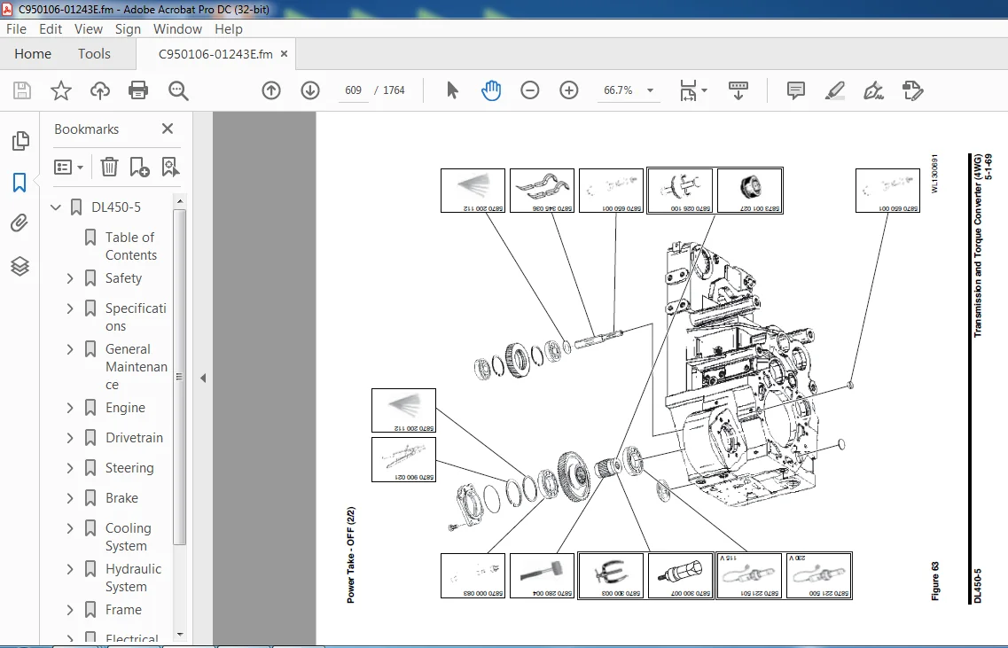
Transmission and Torque Converter (4WG)……………………………………………… 541
Safety Instructions……………………………………………………………. 547
General………………………………………………………………………. 548
Specification……………………………………………………………… 549
Outline…………………………………………………………………… 550
Overview………………………………………………………………….. 551
Section View………………………………………………………………. 552
Hydraulic Circuit (4-speed Transmission)……………………………………… 553
Torque Convertor…………………………………………………………… 554
Electrohydraulic Control with Proportional Valves……………………………… 557
Controller………………………………………………………………… 558
Electric Control System…………………………………………………….. 559
Speed Sensor………………………………………………………………. 562
Transmission Pressure Measuring Point and Connections………………………….. 564
Transmission Electric Components………………………………………………… 566
TCU (Transmission Control Unit)……………………………………………… 568
Transmission Control Valve………………………………………………….. 568
Transmission Oil Temperature Sensor………………………………………….. 568
Engine Pickup Sensor……………………………………………………….. 569
Central Gear Pickup Sensor………………………………………………….. 569
Turbine Pickup Sensor………………………………………………………. 569
Output Speed Sensor………………………………………………………… 569
Shift Lever Switch (DW-3)…………………………………………………… 570
Forward, Reverse Switch Lever……………………………………………….. 571
Fingertip Work Lever (Optional)……………………………………………… 571
Transmission Shift Switch…………………………………………………… 573
T/M Cutoff Sensor………………………………………………………….. 573
LIS Solenoid Valve…………………………………………………………. 573
Transmission Electrical Circuits………………………………………………… 574
Transmission Controller Circuit……………………………………………… 574
Traveling Circuits…………………………………………………………. 575
Downshift…………………………………………………………………. 583
Transmission Cutoff Switch………………………………………………….. 590
Torque Limits for Screws……………………………………………………….. 591
Transmission Oil………………………………………………………………. 592
Oil Grade of Transmission…………………………………………………… 592
Special Tools…………………………………………………………………. 593
List of Special Tools for Disassembly and Reassembly…………………………… 593
Transmission Control Valve……………………………………………………… 613
Disassembly……………………………………………………………….. 613
Reassembly………………………………………………………………… 616
Transmission………………………………………………………………….. 623
Disassembly……………………………………………………………….. 623
Reassembly………………………………………………………………… 649
Failure Code………………………………………………………………….. 732
Transmission and Torque Converter (5WG) (Option)……………………………………… 759
Safety Instructions……………………………………………………………. 763
General………………………………………………………………………. 764
Specification……………………………………………………………… 765
Overview………………………………………………………………….. 766
Hydraulic Circuit (5-speed Transmission)……………………………………… 767
Torque Convertor…………………………………………………………… 768
Transmission Pressure Measuring Point and Connections………………………….. 770
Transmission Electrical Circuits………………………………………………… 772
Transmission Controller Circuit……………………………………………… 772
Traveling Circuits…………………………………………………………. 773
Torque Converter Lockup…………………………………………………….. 774
Torque Limits for Screws……………………………………………………….. 776
Special Tools…………………………………………………………………. 777
List of Special Tools for Disassembly and Reassembly…………………………… 777
Transmission Control Valve……………………………………………………… 782
Disassembly……………………………………………………………….. 782
Reassembly………………………………………………………………… 787
Transmission………………………………………………………………….. 796
Disassembly……………………………………………………………….. 796
Reassembly………………………………………………………………… 823
Front Axle……………………………………………………………………….. 909
Safety Instructions……………………………………………………………. 913
General………………………………………………………………………. 913
Specification……………………………………………………………… 913
Overview………………………………………………………………….. 914
Parts List………………………………………………………………… 915
Lubrication and Maintenance Instructions…………………………………………. 917
Oil Grade…………………………………………………………………. 917
Oil Change………………………………………………………………… 917
Carry Out Wear Measurement on the Multidisk Brake……………………………… 919
Tightening Torques for Screws……………………………………………….. 920
Differential System……………………………………………………………. 921
Theory of Differential Device……………………………………………….. 921
Structure of Differential Device…………………………………………….. 922
LSD………………………………………………………………………….. 923
Overview LSD (Limited Slip Differential)……………………………………… 923
LSD (Limited Slip Differential)……………………………………………… 924
Axle Air Breathing…………………………………………………………….. 925
Special Tools…………………………………………………………………. 926
List of Special Tools for Disassembly and Reassembly…………………………… 926
Removal………………………………………………………………………. 932
Installation………………………………………………………………….. 935
Completing Work……………………………………………………………….. 935
Disassembly and Reassembly……………………………………………………… 936
Disassembly of Output and Brake……………………………………………… 936
Disassembly Axle Housing……………………………………………………. 942
Disassembly Input………………………………………………………….. 943
Disassembly Differentials…………………………………………………… 946
Reassembly Differentials……………………………………………………. 953
Reassembly Input…………………………………………………………… 965
Reassembly Axle Housing…………………………………………………….. 974
Reassembly Output and Brake…………………………………………………. 976
Rear Axle………………………………………………………………………… 989
Safety Instructions……………………………………………………………. 993
General………………………………………………………………………. 993
Specification……………………………………………………………… 993
Overview………………………………………………………………….. 994
Parts List………………………………………………………………… 995
Lubrication and Maintenance Instructions…………………………………………. 997
Oil Grade…………………………………………………………………. 997
Oil Change………………………………………………………………… 997
Carry Out Wear Measurement on the Multidisk Brake……………………………… 999
Tightening Torques for Screws………………………………………………..1000
Differential System…………………………………………………………….1001
Theory of Differential Device………………………………………………..1001
Structure of Differential Device……………………………………………..1002
Axle Air Breathing……………………………………………………………..1003
Special Tools………………………………………………………………….1004
List of Special Tools for Disassembly and Reassembly……………………………1004
Removal……………………………………………………………………….1010
Installation…………………………………………………………………..1014
Completing Work………………………………………………………………..1014
Disassembly and Reassembly………………………………………………………1015
Disassembly of Output and Brake………………………………………………1015
Disassembly Axle Housing…………………………………………………….1021
Disassembly Input…………………………………………………………..1022
Disassembly Differentials……………………………………………………1025
Reassembly Differentials…………………………………………………….1032
Reassembly Input……………………………………………………………1044
Reassembly Axle Housing……………………………………………………..1053
Reassembly Output and Brake………………………………………………….1055
Driveshaft………………………………………………………………………..1067
Safety Instructions…………………………………………………………….1071
General……………………………………………………………………….1072
Overview…………………………………………………………………..1072
Specification………………………………………………………………1072
Removal (Front DriveShaft)………………………………………………………1074
Installation (Front DriveShaft)………………………………………………….1075
Removal (Center DriveShaft)……………………………………………………..1076
Installation (Center DriveShaft)…………………………………………………1078
Removal (Rear DriveShaft)……………………………………………………….1079
Installation (Rear DriveShaft)…………………………………………………..1080
Steering……………………………………………………………………………..1081
Power Steering System………………………………………………………………1083
Safety Instructions…………………………………………………………….1087
General Description…………………………………………………………….1087
Overview…………………………………………………………………..1088
Hydraulic Circuit…………………………………………………………..1089
Theory of Operation…………………………………………………………1090
Steering Unit……………………………………………………………………..1093
Safety Instructions…………………………………………………………….1097
General Description…………………………………………………………….1097
Specifications……………………………………………………………..1099
Overview…………………………………………………………………..1100
Theory of Operation…………………………………………………………1101
Gerotor Operation…………………………………………………………..1102
Relief Valve……………………………………………………………….1102
Steering Pump……………………………………………………………………..1103
Safety Instructions…………………………………………………………….1107
General Description…………………………………………………………….1108
Specifications……………………………………………………………..1108
Overview…………………………………………………………………..1108
Parts List…………………………………………………………………1110
Theory of Operation…………………………………………………………1116
Removal……………………………………………………………………….1118
Installation…………………………………………………………………..1123
Completing Work………………………………………………………………..1123
Disassembly……………………………………………………………………1124
Assembly………………………………………………………………………1126
Flow Amplifier…………………………………………………………………….1129
Safety Instructions…………………………………………………………….1133
General Description…………………………………………………………….1133
Specifications……………………………………………………………..1134
Parts List…………………………………………………………………1136
Theory of Operation…………………………………………………………1137
Removal……………………………………………………………………….1139
Installation…………………………………………………………………..1142
Completing Work………………………………………………………………..1142
Tools…………………………………………………………………………1143
List of Required Tools………………………………………………………1143
Disassembly……………………………………………………………………1144
Assembly………………………………………………………………………1158
Cleaning and Inspection (Wear Limits and Tolerances)……………………………….1172
Cleaning…………………………………………………………………..1172
Inspection and Replacement…………………………………………………..1172
Lubrication………………………………………………………………..1172
Jerk Softener and Accumulator……………………………………………………….1173
Safety Instructions…………………………………………………………….1177
General Description…………………………………………………………….1177
Operation………………………………………………………………….1177
Accumulator……………………………………………………………………1178
Specifications……………………………………………………………..1178
Jerk Softener………………………………………………………………….1178
Specifications……………………………………………………………..1178
Parts List…………………………………………………………………1178
Brake………………………………………………………………………………..1179
Service Brake……………………………………………………………………..1181
Safety Instructions…………………………………………………………….1185
General Description…………………………………………………………….1186
Service Brake System……………………………………………………………1187
Brake and Pilot Supply Valve………………………………………………………..1189
Safety Instructions…………………………………………………………….1193
General Description…………………………………………………………….1193
Overview…………………………………………………………………..1194
Parts List…………………………………………………………………1196
Removal……………………………………………………………………….1197
Installation…………………………………………………………………..1201
Completing Work………………………………………………………………..1201
Charging Block…………………………………………………………………….1203
Safety Instructions…………………………………………………………….1207
General Description…………………………………………………………….1208
Parts List…………………………………………………………………1208
Hydraulic Circuit…………………………………………………………..1209
Parking Brake……………………………………………………………………..1211
Safety Instructions…………………………………………………………….1215
General Description…………………………………………………………….1215
Specification………………………………………………………………1215
Overview…………………………………………………………………..1216
Spring Applied Hydraulic Released Sliding Calliper……………………………..1217
Parts List…………………………………………………………………1219
Functional Description………………………………………………………1220
Mounting and Basic Setting Regulations………………………………………..1222
Adjusting Regulations……………………………………………………….1223
Emergency Release of Parking Brake……………………………………………1223
Maintenance and Repair Work………………………………………………….1224
General……………………………………………………………………1226
Brake Pedal Valve………………………………………………………………….1227
Safety Instructions…………………………………………………………….1231
General Description…………………………………………………………….1231
Specification………………………………………………………………1231
Parts List…………………………………………………………………1232
Theory of Operation…………………………………………………………1233
Accumulator……………………………………………………………………….1235
Safety Instructions…………………………………………………………….1239
General Description…………………………………………………………….1240
Layout…………………………………………………………………….1242
Specifications……………………………………………………………..1242
Brake Filter………………………………………………………………………1243
Safety Instructions…………………………………………………………….1247
Specification………………………………………………………………1248
Overview…………………………………………………………………..1248
Parts List…………………………………………………………………1248
Cooling System………………………………………………………………………..1249
Cooling System…………………………………………………………………….1251
Safety Instructions…………………………………………………………….1255
General Description…………………………………………………………….1255
Function…………………………………………………………………..1256
Hydraulic Circuit…………………………………………………………..1257
Fan Motor Pressure and Fan Speed……………………………………………..1258
Checking Maximum Fan Speed……………………………………………….1259
Fan and Brake Pump…………………………………………………………………1261
Safety Instructions…………………………………………………………….1265
General……………………………………………………………………….1265
Specification………………………………………………………………1265
Sectional View……………………………………………………………..1266
Overview…………………………………………………………………..1267
Port and Hydraulic Circuit……………………………………………….1267
Parts List…………………………………………………………………1268
Theory of Operation…………………………………………………………1270
Circuit………………………………………………………………..1270
Control Section…………………………………………………………1271
Circuit Diagram Related to Fan Drive………………………………………1271
Pump EPPR Valve…………………………………………………………1272
Removal……………………………………………………………………….1274
Installation…………………………………………………………………..1277
Completing Work………………………………………………………………..1277
Disassembly……………………………………………………………………1278
Assembly………………………………………………………………………1282
Tightening Torques………………………………………………………….1287
Sealing Driveshaft………………………………………………………….1287
Sealing Control Valve……………………………………………………….1289
Fan Motor…………………………………………………………………………1291
Safety Instructions…………………………………………………………….1295
Specifications……………………………………………………………..1296
Overview…………………………………………………………………..1296
Port and Hydraulic Circuit……………………………………………….1296
Fan Control Valve………………………………………………………………….1297
Safety Instructions…………………………………………………………….1301
General……………………………………………………………………….1301
Specifications……………………………………………………………..1301
Port and Hydraulic Circuit……………………………………………….1302
Radiator Assembly………………………………………………………………….1303
Safety Instructions…………………………………………………………….1307
General……………………………………………………………………….1307
Overview…………………………………………………………………..1307
Structure………………………………………………………………….1308
Parts List…………………………………………………………………1309
CAC (Charge Air Cooler)…………………………………………………………1310
Overview…………………………………………………………………..1310
Replacing – Hose/Pipe (Charge Air Cooler)……………………………………..1311
Radiator………………………………………………………………………1313
Overview…………………………………………………………………..1313
Theory of Operation…………………………………………………………1313
Radiator Cap……………………………………………………………….1314
Replacing – Radiator Cap…………………………………………………….1315
Replacing Coolant…………………………………………………………..1315
Antifreeze Concentration Tables………………………………………………1316
Transmission Cooling……………………………………………………………1317
General Description…………………………………………………………1317
Layout…………………………………………………………………….1317
Thermostat…………………………………………………………………1318
Hydraulic System………………………………………………………………………1319
Main Pump…………………………………………………………………………1321
Safety Instructions…………………………………………………………….1325
General……………………………………………………………………….1325
Specifications……………………………………………………………..1325
Overview…………………………………………………………………..1326
Theory of Operation…………………………………………………………1328
Parts List…………………………………………………………………1330
Structure………………………………………………………………….1334
Removal……………………………………………………………………….1336
Installation…………………………………………………………………..1341
Completing Work………………………………………………………………..1341
Disassembly……………………………………………………………………1342
Assembly………………………………………………………………………1345
Troubleshooting………………………………………………………………..1348
Maintenance Instructions………………………………………………………..1349
Main Control Valve…………………………………………………………………1351
Safety Instructions…………………………………………………………….1355
General Description…………………………………………………………….1356
Specification………………………………………………………………1357
Hydraulic Circuit…………………………………………………………..1358
Configuration (Port)………………………………………………………..1360
Theory of Operation…………………………………………………………1361
Section View……………………………………………………………….1369
Parts List…………………………………………………………………1370
Removal……………………………………………………………………….1374
Installation…………………………………………………………………..1380
Completing Work………………………………………………………………..1380
Pilot System………………………………………………………………………1381
Safety Instructions…………………………………………………………….1385
General Description…………………………………………………………….1385
Fingertip Joystick……………………………………………………………..1386
Specification………………………………………………………………1386
Port Name………………………………………………………………….1386
Parts List – 2 Lever………………………………………………………..1387
Parts List – 3 Lever………………………………………………………..1388
FNR Joystick…………………………………………………………………..1389
Specification………………………………………………………………1389
Port Name………………………………………………………………….1389
Overview…………………………………………………………………..1389
Parts List…………………………………………………………………1390
Hydraulic System…………………………………………………………………..1393
Safety Instructions…………………………………………………………….1397
Hydraulic Component and Circuit………………………………………………….1398
Hydraulic Components………………………………………………………..1398
Pilot Circuit………………………………………………………………1400
Main Circuit……………………………………………………………….1401
Return Circuit……………………………………………………………..1402
Load Sensing Circuit………………………………………………………..1403
Fan Drive Operation…………………………………………………………….1404
Parking Brake Release…………………………………………………………..1405
Service Brake Operation…………………………………………………………1406
Steering Operation……………………………………………………………..1407
Boom Raise Operation and Load Sensing…………………………………………….1408
Boom Down Operation…………………………………………………………….1409
Boom Floating Operation…………………………………………………………1410
Bucket Crowd Operation………………………………………………………….1411
Bucket Dump Operation…………………………………………………………..1412
Combined Bucket Crowd and Boom Down Operation……………………………………..1413
Load Isolation System (LIS)……………………………………………………..1414
Hydraulic System Troubleshooting…………………………………………………….1415
Safety Instructions…………………………………………………………….1419
Hydraulic System……………………………………………………………….1420
Engine Started but Machine Does Not Operate……………………………………1420
Hydraulic Oil Is Cloudy……………………………………………………..1421
Hydraulic Oil or Engine Overheated……………………………………………1422
Parking Brakes Does Not Work…………………………………………………1424
Service Brakes Does Not Work…………………………………………………1425
Boom, Bucket Speed Is Slow…………………………………………………..1426
Does Not Work the Boom Floating………………………………………………1428
Steering Wheel Is Heavy to Turn………………………………………………1430
Does Not Operated LIS……………………………………………………….1431
Frame………………………………………………………………………………..1433
Articulation Center………………………………………………………………..1435
Safety Instructions…………………………………………………………….1439
General Description…………………………………………………………….1439
Maintenance Standard………………………………………………………..1440
Cabin…………………………………………………………………………….1443
Safety Instructions…………………………………………………………….1447
Cabin Identification……………………………………………………………1447
Roll-over Protective Structure (ROPS)/Falling Object Protective Structure (FOPS)…..1447
Dimensions of Cabin Glass……………………………………………………….1449
Removal and Installation of Cabin Glass…………………………………………..1454
Removal of Cabin Glass………………………………………………………1454
Installation of Cabin Glass………………………………………………….1456
Counterweight……………………………………………………………………..1461
Safety Instructions…………………………………………………………….1465
General……………………………………………………………………….1466
Overview…………………………………………………………………..1466
Oil Tank………………………………………………………………………….1467
Safety Instructions…………………………………………………………….1471
General Description…………………………………………………………….1471
Specifications……………………………………………………………..1471
Parts List…………………………………………………………………1472
Air Breather……………………………………………………………….1474
Fuel Tank…………………………………………………………………………1475
Safety Instructions…………………………………………………………….1479
General Description…………………………………………………………….1479
Specifications……………………………………………………………..1479
Parts List…………………………………………………………………1480
Cylinders…………………………………………………………………………1483
Safety Instructions…………………………………………………………….1487
General……………………………………………………………………….1487
General Description…………………………………………………………1487
Specification………………………………………………………………1487
Parts List…………………………………………………………………1488
Theory of Operation…………………………………………………………1494
Seal of Cylinder……………………………………………………………1495
Special Tools and Materials……………………………………………………..1497
Piston Nut…………………………………………………………………1497
Piston Jig…………………………………………………………………1498
Steel Bushing Jig…………………………………………………………..1499
Dust Wiper Jig……………………………………………………………..1500
Slipper Seal Jig……………………………………………………………1501
Slipper Seal Straightening Jig……………………………………………….1502
Rod Bushing (DD-bushing) Pushing-in Jig……………………………………….1503
Disassembly……………………………………………………………………1504
Reassembly…………………………………………………………………….1509
Troubleshooting………………………………………………………………..1513
Electrical System……………………………………………………………………..1515
Electrical System………………………………………………………………….1517
Safety Instructions…………………………………………………………….1521
Overview………………………………………………………………………1521
Electric Supply System………………………………………………………….1522
Engine Starting Circuit…………………………………………………………1524
Operation During Start Process……………………………………………….1524
Operation After Start Process………………………………………………..1526
Engine Stop System……………………………………………………………..1527
Engine Emergency Start System……………………………………………………1528
Charging System………………………………………………………………..1529
Power Mode Control……………………………………………………………..1530
Engine Control System…………………………………………………………..1531
Accelerator Pedal…………………………………………………………..1532
Electrical Steering Control………………………………………………….1533
Electric Joystick…………………………………………………………..1534
Electric MCV Control………………………………………………………..1535
Electric Joystick (Boom)…………………………………………………….1536
Electric Joystick (Bucket)…………………………………………………..1537
Auto Idle Control…………………………………………………………..1538
Electric Detent System………………………………………………………….1539
Electrical Circuit………………………………………………………….1539
Boom Kick-out………………………………………………………………1540
Return to Dig………………………………………………………………1541
Cooling Fan Control System………………………………………………………1542
Outline……………………………………………………………………1542
Diagram……………………………………………………………………1542
Electrical Diagram………………………………………………………….1543
Parts of Cooling Fan Control System…………………………………………..1544
Operation of Cooling Fan Control System……………………………………….1546
Emergency Steering System (Option)……………………………………………….1548
Block Diagram………………………………………………………………1548
Emergency Steering System Components………………………………………….1549
Emergency Steering System Electrical Circuit…………………………………..1552
Lighting System………………………………………………………………..1554
Light Circuit………………………………………………………………1554
Monitoring System………………………………………………………………1558
Instrument Panel……………………………………………………………1559
Function Check……………………………………………………………..1559
Monitoring System Schematic………………………………………………….1560
Operation……………………………………………………………………..1562
Instruments Gauge…………………………………………………………..1562
Indicator Lights……………………………………………………………1562
Initial Operation…………………………………………………………..1564
Multifunction Display……………………………………………………….1565
Indication of Warning Lights…………………………………………………1568
Indication of Indicator Lights……………………………………………….1570
Graphic Information Area Display…………………………………………………1572
Overview…………………………………………………………………..1572
Main Menus for the Graphic Display Area……………………………………….1572
Menu Selector Buttons……………………………………………………….1572
User Menu………………………………………………………………….1573
Service Menu……………………………………………………………….1587
Information of Machine Operation……………………………………………..1597
Failure Code…………………………………………………………………..1604
Failure Code at Machine……………………………………………………..1604
Failure Code at Engine Side………………………………………………….1608
Failure Code at Transmission Side…………………………………………….1623
Failure Code at Electric Steering Side………………………………………..1627
FMIs (Failure Mode Identifier)……………………………………………….1629
Windshield Wiper……………………………………………………………….1630
Front Windshield Wiper………………………………………………………1630
Rear Windshield Wiper……………………………………………………….1632
Air Conditioner……………………………………………………………………1635
Safety Instructions…………………………………………………………….1639
General Description…………………………………………………………….1640
Internal and External Filters………………………………………………..1641
Air-conditioning System Layout……………………………………………….1642
Air Conditioner/Heater Circuit Diagram………………………………………..1643
Air Conditioner/Heater Unit………………………………………………….1644
Ambient Air Temperature Sensor……………………………………………….1649
Sun Sensor…………………………………………………………………1650
Control Panel………………………………………………………………1650
Compressor…………………………………………………………………1657
Receiver Dryer……………………………………………………………..1657
Troubleshooting………………………………………………………………..1658
Refrigerant System Repairs………………………………………………………1660
Refrigerant Safe Handling Procedures………………………………………….1660
Repair and Replacement Procedure……………………………………………..1661
Refrigerant Recovery………………………………………………………..1663
Vacuuming Refrigerant System…………………………………………………1663
Leakage Check………………………………………………………………1665
Refrigerant Charging………………………………………………………..1665
Inspecting System For Leakage………………………………………………..1667
Option……………………………………………………………………………….1669
Emergency Steering…………………………………………………………………1671
Safety Instructions…………………………………………………………….1675
General Description…………………………………………………………1675
Specifications……………………………………………………………..1675
Theory of Operation…………………………………………………………1676
Hydraulic Circuit…………………………………………………………..1676
Parts List…………………………………………………………………1677
Caution for Installation…………………………………………………….1677
Installation Procedure………………………………………………………….1678
Emergency Steering………………………………………………………….1678
Emergency Steering – Electric………………………………………………..1680
After Installation Precautions……………………………………………….1681
Emergency Steering Function Test……………………………………………..1681
Emergency Steering Automatic Test…………………………………………….1682
Load Isolation System………………………………………………………………1683
Safety Instructions…………………………………………………………….1687
General Description…………………………………………………………….1687
Overview…………………………………………………………………..1688
Hydraulic Circuit…………………………………………………………..1690
Accumulator Charging Method………………………………………………….1690
LIS Valve……………………………………………………………………..1692
Specification………………………………………………………………1692
Parts List…………………………………………………………………1693
Accumulator……………………………………………………………………1694
Specification………………………………………………………………1694
Parts List…………………………………………………………………1694
3rd Control Valve………………………………………………………………….1695
Safety Instructions…………………………………………………………….1699
General……………………………………………………………………….1699
Specification………………………………………………………………1699
Overview…………………………………………………………………..1700
Hydraulic Circuit…………………………………………………………..1700
Theory of Operation…………………………………………………………1701
Parts List…………………………………………………………………1702
Removal……………………………………………………………………….1703
Installation…………………………………………………………………..1706
Completing Work………………………………………………………………..1706
Disassembly and Assembly………………………………………………………..1707
General Cautions……………………………………………………………1707
Assembly and Disassembly of Spool and Over Load Relief Valve…………………….1708
Performance Tests………………………………………………………………1709
Auto Grease System…………………………………………………………………1711
Safety Instructions…………………………………………………………….1715
General Description…………………………………………………………….1715
Overview…………………………………………………………………..1716
Location…………………………………………………………………..1718
Theory of Operation…………………………………………………………1719
Pump Element……………………………………………………………1719
Grease Low Leveling……………………………………………………..1720
Feeder…………………………………………………………………1721
Error Sensing…………………………………………………………..1722
Pump………………………………………………………………………….1723
Overview…………………………………………………………………..1723
The Central Lubrication Pump……………………………………………..1723
Note on the Rating Plate…………………………………………………1724
Location…………………………………………………………………..1724
Specification………………………………………………………………1725
Parts List…………………………………………………………………1726
Pump Element……………………………………………………………1728
Check Valve…………………………………………………………….1729
Pressure Relief Valve……………………………………………………1729
Power Supply 24 VDC……………………………………………………..1730
Connectivity for Timer Operation with System Monitoring……………………..1730
Connector Pin Assignment in Timer Operation………………………………..1730
Pump Cable…………………………………………………………………1731
Overview……………………………………………………………….1731
Connector 1…………………………………………………………….1731
Connector 2…………………………………………………………….1732
Connector 3…………………………………………………………….1732
Fill Level Switch……………………………………………………….1732
Monitoring Lubrication Cycle by Piston Detector…………………………….1733
Approved Lubricants…………………………………………………………1734
Operation………………………………………………………………….1735
Pump…………………………………………………………………..1735
Fill Level Monitoring……………………………………………………1735
Malfunctions on Pump Unit in Progressive System…………………………….1735
Timer Operation…………………………………………………………1736
Maintenance, Repair…………………………………………………………1737
Maintenance…………………………………………………………….1737
Repair…………………………………………………………………1738
Feeder………………………………………………………………………..1739
Feeder (Front Frame)………………………………………………………..1739
General Description……………………………………………………..1739
Location and Parts List………………………………………………….1740
Dimension………………………………………………………………1741
Main Feeder Connector……………………………………………………1743
Feeder (Rear Frame)…………………………………………………………1743
General Description……………………………………………………..1743
Overview……………………………………………………………….1743
Location and Parts List………………………………………………….1744
Dimension………………………………………………………………1745
Feeder (Tilt lever)…………………………………………………………1746
General Description……………………………………………………..1746
Overview……………………………………………………………….1746
Location and Parts List………………………………………………….1747
Dimension………………………………………………………………1748
Replace Hose Using Service kit……………………………………………….1749
Hoses for Self Assembly………………………………………………….1749
Troubleshooting………………………………………………………………..1751
Grease Pump Fault…………………………………………………………..1753
Grease System Faults………………………………………………………..1753
Schematic…………………………………………………………………………….1755
Hydraulic Schematic/ Electrical Schematic…………………………………………….1757
Hydraulic Schematic…………………………………………………………….1759
Electrical Schematic……………………………………………………………1761DL450-5…………………………………………………………………………………. 0
Table of Contents…………………………………………………………………….. 7
Safety………………………………………………………………………………. 9
Wheel Loader Safety……………………………………………………………….. 11
Safety Instructions……………………………………………………………. 15
Safety Messages……………………………………………………………….. 15
General………………………………………………………………………. 17
Safe Operation is Operator’s Responsibility…………………………………… 17
Know Your Machine………………………………………………………….. 17
Proper Work Tools and Attachments……………………………………………. 17
Pressurized Fluids…………………………………………………………. 18
Flying or Falling Objects…………………………………………………… 19
Personal Protective Equipment (PPE)………………………………………….. 19
Correction of Machine Problems………………………………………………. 20
Crushing and Cutting……………………………………………………….. 20
Hot Coolant and Oils – Burn Prevention……………………………………….. 21
Fire and Explosion Prevention……………………………………………….. 21
Fire Extinguisher and First-Aid Kit (Emergency Medical Kit)…………………….. 25
Electrical System and Electrical Shock……………………………………….. 25
Roll-over Protective Structure (ROPS)/ Falling Object Protective Structure (FOPS)…. 26
Operation…………………………………………………………………….. 28
Before Engine Starting……………………………………………………… 28
Work Site…………………………………………………………………. 28
Check Tire Pressure and Condition……………………………………………. 29
Mounting/Dismounting……………………………………………………….. 29
Cleaning………………………………………………………………….. 30
Operator Station…………………………………………………………… 30
Seat Belt…………………………………………………………………. 31
Visibility Information……………………………………………………… 32
Boost Starting or Charging Engine Batteries…………………………………… 33
Starting Engine……………………………………………………………. 34
Traveling…………………………………………………………………. 34
Lifting and Digging………………………………………………………… 36
Digging Beneath Overhangs…………………………………………………… 36
Digging Beneath Wheel Loader………………………………………………… 36
Operation on Slopes………………………………………………………… 37
Attachment………………………………………………………………… 38
Equipment Lowering with Engine Stopped……………………………………….. 38
Preventing Risk of Injuries or Death From Boom and Bucket………………………. 38
Engine Stop……………………………………………………………….. 40
Parking Machine……………………………………………………………. 40
Maintenance…………………………………………………………………… 41
Warning Tag……………………………………………………………….. 43
Cleaning………………………………………………………………….. 44
Proper Tools and Clothing…………………………………………………… 44
Disassembling Precautions…………………………………………………… 44
Use of Lighting……………………………………………………………. 45
Fire and Explosion Prevention……………………………………………….. 45
Burn Prevention……………………………………………………………. 46
Rubber That Contains Fluorides………………………………………………. 47
Rubber and Plastics………………………………………………………… 48
Welding Repairs……………………………………………………………. 49
Working on Machine…………………………………………………………. 50
Lock Inspection Covers……………………………………………………… 51
Accumulator……………………………………………………………….. 51
Compressed Air…………………………………………………………….. 51
Supports and Blocking for Work Equipment……………………………………… 52
High-pressure Lines, Tubes and Hoses…………………………………………. 52
Battery…………………………………………………………………… 53
Preservation/Storing Machine………………………………………………… 54
Transportation………………………………………………………………… 56
Obey State and Local Over-the-Road Laws and Regulations………………………… 56
Loading and Unloading………………………………………………………. 56
Transporting Machine……………………………………………………….. 57
Environment and Circumstances…………………………………………………… 58
Work Site Areas Requiring Extra Caution………………………………………. 58
High-voltage Cables………………………………………………………… 60
Underground Operation………………………………………………………. 60
Working in Water…………………………………………………………… 61
Working in Contaminated Environment………………………………………….. 61
Operation in Extreme Conditions……………………………………………… 62
Exhaust Ventilation………………………………………………………… 66
Asbestos Information……………………………………………………….. 66
Silica Dust Information…………………………………………………….. 67
Disposal of Hazardous Materials……………………………………………… 67
Sound…………………………………………………………………….. 67
Vibration Information………………………………………………………. 68
Specifications……………………………………………………………………….. 71
Specification…………………………………………………………………….. 73
Safety Instructions……………………………………………………………. 77
General………………………………………………………………………. 77
Component Locations……………………………………………………………. 78
Working Range and Dimensions……………………………………………………. 82
Working Capacities…………………………………………………………….. 84
Bucket Capacity……………………………………………………………. 84
Stability Data (EN – and ISO – Norms)………………………………………… 84
General Specifications…………………………………………………………. 85
Performance Tests……………………………………………………………… 86
Purpose of Performance Tests………………………………………………… 86
Kinds of Tests…………………………………………………………….. 86
Performance Standards………………………………………………………. 86
Precautions for Evaluation of Test Data………………………………………. 86
Definition of “Performance Standard”…………………………………………. 86
Preparation for Performance Tests……………………………………………….. 87
The Machine……………………………………………………………….. 87
Test Area…………………………………………………………………. 87
Precautions……………………………………………………………….. 87
Make Precise Measurement……………………………………………………. 87
Operational Performance Standard Table…………………………………………… 88
Operational Performance Test……………………………………………………. 90
Engine Speed………………………………………………………………. 90
Front Speed……………………………………………………………….. 92
Natural Subsidence of Cylinder………………………………………………. 93
Travel Speed – Acceleration and Deceleration………………………………….. 94
Steering Time……………………………………………………………… 95
Pressure Set………………………………………………………………. 96
Approximate Weight of Workload Materials…………………………………………. 98
Material Weight……………………………………………………………. 98
General Maintenance…………………………………………………………………… 101
General Maintenance Instructions.pdf………………………………………………… 103
Safety Instructions……………………………………………………………. 107
Welding Precautions and Instructions…………………………………………….. 108
Hydraulic System – General Precautions…………………………………………… 109
Maintenance Service and Repair Procedure…………………………………………. 111
General Precautions………………………………………………………… 111
Hydraulic System Cleanliness and Oil Leaks……………………………………….. 112
Maintenance Precautions for Hydraulic System Service…………………………… 112
Oil Leakage Precautions…………………………………………………….. 113
Cleaning and Inspection………………………………………………………… 114
General Instructions……………………………………………………….. 114
Bearing Inspection…………………………………………………………. 115
Standard Torques………………………………………………………………….. 123
Safety Instructions……………………………………………………………. 127
Torque Values for Standard Metric Fasteners………………………………………. 128
Torque Values for Standard U.S. Fasteners………………………………………… 129
Type 8 Phosphate Coated Hardware………………………………………………… 131
Torque Values for Hose Clamps…………………………………………………… 132
ORFS Swivel Nut Recommended Torque………………………………………………. 132
Torque Values for Split Flanges…………………………………………………. 133
Torque Wrench Extension Tools…………………………………………………… 134
Torque Multiplication………………………………………………………. 134
Other Uses for Torque Wrench Extension Tools………………………………….. 135
Tightening Torque Specifications (Metric)…………………………………….. 136
Engine………………………………………………………………………………. 139
Engine…………………………………………………………………………… 141
Safety Instructions……………………………………………………………. 147
Overview……………………………………………………………………… 148
Inspection……………………………………………………………………. 149
Cleaning the Engine………………………………………………………… 149
Special Tools…………………………………………………………………. 149
Mounting the Engine in a Universal Stand……………………………………… 159
Engine Identification………………………………………………………….. 160
Engine Data Plate………………………………………………………….. 160
Engine Specification…………………………………………………………… 161
Engine Performance Curves………………………………………………………. 162
Tightening Torques…………………………………………………………….. 164
Normal Tightening Torque……………………………………………………. 164
Special Tightening Torque…………………………………………………… 168
Cylinder……………………………………………………………………… 194
Cylinder Head……………………………………………………………… 194
Valve Mechanism……………………………………………………………. 212
Cylinder Block…………………………………………………………….. 216
Cylinder Liner…………………………………………………………….. 230
Flywheel Housing…………………………………………………………… 237
Front Cover……………………………………………………………….. 240
Oil Mist Separator…………………………………………………………. 242
Actuating System………………………………………………………………. 248
Camshaft………………………………………………………………….. 248
Connecting Rod…………………………………………………………….. 255
Crankshaft………………………………………………………………… 258
Flywheel………………………………………………………………….. 267
Piston……………………………………………………………………. 272
Roller Tappet……………………………………………………………… 278
Intake Manifold……………………………………………………………. 279
Torsion Damper…………………………………………………………….. 280
Belt Circuit………………………………………………………………. 281
Timing Gear……………………………………………………………….. 287
Lubrication System…………………………………………………………….. 293
General Information………………………………………………………… 293
Centrifugal Oil Cleaner…………………………………………………….. 295
Oil Cooler………………………………………………………………… 300
Oil Filter………………………………………………………………… 303
Oil Pump………………………………………………………………….. 304
Oil Sump………………………………………………………………….. 306
Oil Pressure Sensor………………………………………………………… 308
Troubleshooting Chips Found in the Engine…………………………………….. 309
Troubleshooting the Lubrication System……………………………………….. 313
Lubrication Oil Consumption…………………………………………………. 314
Exhaust System………………………………………………………………… 317
General Information………………………………………………………… 317
T113, Exhaust Temperature Sensor Before Catalytic Converter…………………….. 333
T115, NOx Sensor…………………………………………………………… 334
T131 NOx Sensor……………………………………………………………. 336
T116, Reductant Pick-up Unit………………………………………………… 338
Evaporator………………………………………………………………… 343
V117 Reductant Doser……………………………………………………….. 344
V118, Coolant Valve for Heating the Reductant System…………………………… 349
V183 Reductant Pump………………………………………………………… 351
H25, H26 Electrically Heated Reductant Hose…………………………………… 362
M4000 Electric Exhaust Brake………………………………………………… 364
Reductant Tank…………………………………………………………….. 370
Oxidation Catalytic Converter……………………………………………….. 377
Exhaust Manifold…………………………………………………………… 379
Variable Geometry Turbocharger………………………………………………. 385
EGR System………………………………………………………………… 393
EGR Valve…………………………………………………………………. 400
EGR Cooler………………………………………………………………… 405
Cooling System………………………………………………………………… 407
Internal Cleaning of Cooling System………………………………………….. 410
Charge Air Cooler………………………………………………………….. 411
Charge Air Temperature Sensor……………………………………………….. 413
Charge Air Pressure Sensor………………………………………………….. 415
Thermostat………………………………………………………………… 416
Coolant Pump………………………………………………………………. 419
Coolant Temperature Sensor………………………………………………….. 420
Fuel System…………………………………………………………………… 422
General Information………………………………………………………… 422
Accumulator……………………………………………………………….. 428
Fuel Manifold……………………………………………………………… 429
Overflow Valve…………………………………………………………….. 436
Feed Pump…………………………………………………………………. 440
Injector………………………………………………………………….. 446
Fuel Filter……………………………………………………………….. 452
Fuel Heater……………………………………………………………….. 458
Fuel System Troubleshooting…………………………………………………. 459
Electrical System……………………………………………………………… 472
E44, Control Unit EMS………………………………………………………. 472
Control Unit EEC…………………………………………………………… 489
Clamping and Routing the Electrical Cables……………………………………. 494
Engine Speed Sensor………………………………………………………… 495
T110 Oil Level Sensor………………………………………………………. 497
T111, Fuel Pressure Sensor………………………………………………….. 498
T125, Exhaust Back Pressure Sensor…………………………………………… 500
T135, Camshaft Position Sensor………………………………………………. 501
V109, Solenoid Valve for Charge Pressure……………………………………… 503
V120, Fuel Inlet Metering Valve……………………………………………… 504
V141, V142, V143, V144, V145, V146 Solenoid Valve for Injector………………….. 506
T8, Coolant Level Monitor…………………………………………………… 507
P3, Alternator…………………………………………………………….. 508
M1, Starter Motor………………………………………………………….. 518
Electrical Parts…………………………………………………………… 521
EMS S8 (1/2)………………………………………………………………. 533
EMS S8 (2/2)………………………………………………………………. 535
EEC, EEC3 Exhaust Emission Control…………………………………………… 537
Drivetrain…………………………………………………………………………… 539
Transmission and Torque Converter (4WG)……………………………………………… 541
Safety Instructions……………………………………………………………. 547
General………………………………………………………………………. 548
Specification……………………………………………………………… 549
Outline…………………………………………………………………… 550
Overview………………………………………………………………….. 551
Section View………………………………………………………………. 552
Hydraulic Circuit (4-speed Transmission)……………………………………… 553
Torque Convertor…………………………………………………………… 554
Electrohydraulic Control with Proportional Valves……………………………… 557
Controller………………………………………………………………… 558
Electric Control System…………………………………………………….. 559
Speed Sensor………………………………………………………………. 562
Transmission Pressure Measuring Point and Connections………………………….. 564
Transmission Electric Components………………………………………………… 566
TCU (Transmission Control Unit)……………………………………………… 568
Transmission Control Valve………………………………………………….. 568
Transmission Oil Temperature Sensor………………………………………….. 568
Engine Pickup Sensor……………………………………………………….. 569
Central Gear Pickup Sensor………………………………………………….. 569
Turbine Pickup Sensor………………………………………………………. 569
Output Speed Sensor………………………………………………………… 569
Shift Lever Switch (DW-3)…………………………………………………… 570
Forward, Reverse Switch Lever……………………………………………….. 571
Fingertip Work Lever (Optional)……………………………………………… 571
Transmission Shift Switch…………………………………………………… 573
T/M Cutoff Sensor………………………………………………………….. 573
LIS Solenoid Valve…………………………………………………………. 573
Transmission Electrical Circuits………………………………………………… 574
Transmission Controller Circuit……………………………………………… 574
Traveling Circuits…………………………………………………………. 575
Downshift…………………………………………………………………. 583
Transmission Cutoff Switch………………………………………………….. 590
Torque Limits for Screws……………………………………………………….. 591
Transmission Oil………………………………………………………………. 592
Oil Grade of Transmission…………………………………………………… 592
Special Tools…………………………………………………………………. 593
List of Special Tools for Disassembly and Reassembly…………………………… 593
Transmission Control Valve……………………………………………………… 613
Disassembly……………………………………………………………….. 613
Reassembly………………………………………………………………… 616
Transmission………………………………………………………………….. 623
Disassembly……………………………………………………………….. 623
Reassembly………………………………………………………………… 649
Failure Code………………………………………………………………….. 732
Transmission and Torque Converter (5WG) (Option)……………………………………… 759
Safety Instructions……………………………………………………………. 763
General………………………………………………………………………. 764
Specification……………………………………………………………… 765
Overview………………………………………………………………….. 766
Hydraulic Circuit (5-speed Transmission)……………………………………… 767
Torque Convertor…………………………………………………………… 768
Transmission Pressure Measuring Point and Connections………………………….. 770
Transmission Electrical Circuits………………………………………………… 772
Transmission Controller Circuit……………………………………………… 772
Traveling Circuits…………………………………………………………. 773
Torque Converter Lockup…………………………………………………….. 774
Torque Limits for Screws……………………………………………………….. 776
Special Tools…………………………………………………………………. 777
List of Special Tools for Disassembly and Reassembly…………………………… 777
Transmission Control Valve……………………………………………………… 782
Disassembly……………………………………………………………….. 782
Reassembly………………………………………………………………… 787
Transmission………………………………………………………………….. 796
Disassembly……………………………………………………………….. 796
Reassembly………………………………………………………………… 823
Front Axle……………………………………………………………………….. 909
Safety Instructions……………………………………………………………. 913
General………………………………………………………………………. 913
Specification……………………………………………………………… 913
Overview………………………………………………………………….. 914
Parts List………………………………………………………………… 915
Lubrication and Maintenance Instructions…………………………………………. 917
Oil Grade…………………………………………………………………. 917
Oil Change………………………………………………………………… 917
Carry Out Wear Measurement on the Multidisk Brake……………………………… 919
Tightening Torques for Screws……………………………………………….. 920
Differential System……………………………………………………………. 921
Theory of Differential Device……………………………………………….. 921
Structure of Differential Device…………………………………………….. 922
LSD………………………………………………………………………….. 923
Overview LSD (Limited Slip Differential)……………………………………… 923
LSD (Limited Slip Differential)……………………………………………… 924
Axle Air Breathing…………………………………………………………….. 925
Special Tools…………………………………………………………………. 926
List of Special Tools for Disassembly and Reassembly…………………………… 926
Removal………………………………………………………………………. 932
Installation………………………………………………………………….. 935
Completing Work……………………………………………………………….. 935
Disassembly and Reassembly……………………………………………………… 936
Disassembly of Output and Brake……………………………………………… 936
Disassembly Axle Housing……………………………………………………. 942
Disassembly Input………………………………………………………….. 943
Disassembly Differentials…………………………………………………… 946
Reassembly Differentials……………………………………………………. 953
Reassembly Input…………………………………………………………… 965
Reassembly Axle Housing…………………………………………………….. 974
Reassembly Output and Brake…………………………………………………. 976
Rear Axle………………………………………………………………………… 989
Safety Instructions……………………………………………………………. 993
General………………………………………………………………………. 993
Specification……………………………………………………………… 993
Overview………………………………………………………………….. 994
Parts List………………………………………………………………… 995
Lubrication and Maintenance Instructions…………………………………………. 997
Oil Grade…………………………………………………………………. 997
Oil Change………………………………………………………………… 997
Carry Out Wear Measurement on the Multidisk Brake……………………………… 999
Tightening Torques for Screws………………………………………………..1000
Differential System…………………………………………………………….1001
Theory of Differential Device………………………………………………..1001
Structure of Differential Device……………………………………………..1002
Axle Air Breathing……………………………………………………………..1003
Special Tools………………………………………………………………….1004
List of Special Tools for Disassembly and Reassembly……………………………1004
Removal……………………………………………………………………….1010
Installation…………………………………………………………………..1014
Completing Work………………………………………………………………..1014
Disassembly and Reassembly………………………………………………………1015
Disassembly of Output and Brake………………………………………………1015
Disassembly Axle Housing…………………………………………………….1021
Disassembly Input…………………………………………………………..1022
Disassembly Differentials……………………………………………………1025
Reassembly Differentials…………………………………………………….1032
Reassembly Input……………………………………………………………1044
Reassembly Axle Housing……………………………………………………..1053
Reassembly Output and Brake………………………………………………….1055
Driveshaft………………………………………………………………………..1067
Safety Instructions…………………………………………………………….1071
General……………………………………………………………………….1072
Overview…………………………………………………………………..1072
Specification………………………………………………………………1072
Removal (Front DriveShaft)………………………………………………………1074
Installation (Front DriveShaft)………………………………………………….1075
Removal (Center DriveShaft)……………………………………………………..1076
Installation (Center DriveShaft)…………………………………………………1078
Removal (Rear DriveShaft)……………………………………………………….1079
Installation (Rear DriveShaft)…………………………………………………..1080
Steering……………………………………………………………………………..1081
Power Steering System………………………………………………………………1083
Safety Instructions…………………………………………………………….1087
General Description…………………………………………………………….1087
Overview…………………………………………………………………..1088
Hydraulic Circuit…………………………………………………………..1089
Theory of Operation…………………………………………………………1090
Steering Unit……………………………………………………………………..1093
Safety Instructions…………………………………………………………….1097
General Description…………………………………………………………….1097
Specifications……………………………………………………………..1099
Overview…………………………………………………………………..1100
Theory of Operation…………………………………………………………1101
Gerotor Operation…………………………………………………………..1102
Relief Valve……………………………………………………………….1102
Steering Pump……………………………………………………………………..1103
Safety Instructions…………………………………………………………….1107
General Description…………………………………………………………….1108
Specifications……………………………………………………………..1108
Overview…………………………………………………………………..1108
Parts List…………………………………………………………………1110
Theory of Operation…………………………………………………………1116
Removal……………………………………………………………………….1118
Installation…………………………………………………………………..1123
Completing Work………………………………………………………………..1123
Disassembly……………………………………………………………………1124
Assembly………………………………………………………………………1126
Flow Amplifier…………………………………………………………………….1129
Safety Instructions…………………………………………………………….1133
General Description…………………………………………………………….1133
Specifications……………………………………………………………..1134
Parts List…………………………………………………………………1136
Theory of Operation…………………………………………………………1137
Removal……………………………………………………………………….1139
Installation…………………………………………………………………..1142
Completing Work………………………………………………………………..1142
Tools…………………………………………………………………………1143
List of Required Tools………………………………………………………1143
Disassembly……………………………………………………………………1144
Assembly………………………………………………………………………1158
Cleaning and Inspection (Wear Limits and Tolerances)……………………………….1172
Cleaning…………………………………………………………………..1172
Inspection and Replacement…………………………………………………..1172
Lubrication………………………………………………………………..1172
Jerk Softener and Accumulator……………………………………………………….1173
Safety Instructions…………………………………………………………….1177
General Description…………………………………………………………….1177
Operation………………………………………………………………….1177
Accumulator……………………………………………………………………1178
Specifications……………………………………………………………..1178
Jerk Softener………………………………………………………………….1178
Specifications……………………………………………………………..1178
Parts List…………………………………………………………………1178
Brake………………………………………………………………………………..1179
Service Brake……………………………………………………………………..1181
Safety Instructions…………………………………………………………….1185
General Description…………………………………………………………….1186
Service Brake System……………………………………………………………1187
Brake and Pilot Supply Valve………………………………………………………..1189
Safety Instructions…………………………………………………………….1193
General Description…………………………………………………………….1193
Overview…………………………………………………………………..1194
Parts List…………………………………………………………………1196
Removal……………………………………………………………………….1197
Installation…………………………………………………………………..1201
Completing Work………………………………………………………………..1201
Charging Block…………………………………………………………………….1203
Safety Instructions…………………………………………………………….1207
General Description…………………………………………………………….1208
Parts List…………………………………………………………………1208
Hydraulic Circuit…………………………………………………………..1209
Parking Brake……………………………………………………………………..1211
Safety Instructions…………………………………………………………….1215
General Description…………………………………………………………….1215
Specification………………………………………………………………1215
Overview…………………………………………………………………..1216
Spring Applied Hydraulic Released Sliding Calliper……………………………..1217
Parts List…………………………………………………………………1219
Functional Description………………………………………………………1220
Mounting and Basic Setting Regulations………………………………………..1222
Adjusting Regulations……………………………………………………….1223
Emergency Release of Parking Brake……………………………………………1223
Maintenance and Repair Work………………………………………………….1224
General……………………………………………………………………1226
Brake Pedal Valve………………………………………………………………….1227
Safety Instructions…………………………………………………………….1231
General Description…………………………………………………………….1231
Specification………………………………………………………………1231
Parts List…………………………………………………………………1232
Theory of Operation…………………………………………………………1233
Accumulator……………………………………………………………………….1235
Safety Instructions…………………………………………………………….1239
General Description…………………………………………………………….1240
Layout…………………………………………………………………….1242
Specifications……………………………………………………………..1242
Brake Filter………………………………………………………………………1243
Safety Instructions…………………………………………………………….1247
Specification………………………………………………………………1248
Overview…………………………………………………………………..1248
Parts List…………………………………………………………………1248
Cooling System………………………………………………………………………..1249
Cooling System…………………………………………………………………….1251
Safety Instructions…………………………………………………………….1255
General Description…………………………………………………………….1255
Function…………………………………………………………………..1256
Hydraulic Circuit…………………………………………………………..1257
Fan Motor Pressure and Fan Speed……………………………………………..1258
Checking Maximum Fan Speed……………………………………………….1259
Fan and Brake Pump…………………………………………………………………1261
Safety Instructions…………………………………………………………….1265
General……………………………………………………………………….1265
Specification………………………………………………………………1265
Sectional View……………………………………………………………..1266
Overview…………………………………………………………………..1267
Port and Hydraulic Circuit……………………………………………….1267
Parts List…………………………………………………………………1268
Theory of Operation…………………………………………………………1270
Circuit………………………………………………………………..1270
Control Section…………………………………………………………1271
Circuit Diagram Related to Fan Drive………………………………………1271
Pump EPPR Valve…………………………………………………………1272
Removal……………………………………………………………………….1274
Installation…………………………………………………………………..1277
Completing Work………………………………………………………………..1277
Disassembly……………………………………………………………………1278
Assembly………………………………………………………………………1282
Tightening Torques………………………………………………………….1287
Sealing Driveshaft………………………………………………………….1287
Sealing Control Valve……………………………………………………….1289
Fan Motor…………………………………………………………………………1291
Safety Instructions…………………………………………………………….1295
Specifications……………………………………………………………..1296
Overview…………………………………………………………………..1296
Port and Hydraulic Circuit……………………………………………….1296
Fan Control Valve………………………………………………………………….1297
Safety Instructions…………………………………………………………….1301
General……………………………………………………………………….1301
Specifications……………………………………………………………..1301
Port and Hydraulic Circuit……………………………………………….1302
Radiator Assembly………………………………………………………………….1303
Safety Instructions…………………………………………………………….1307
General……………………………………………………………………….1307
Overview…………………………………………………………………..1307
Structure………………………………………………………………….1308
Parts List…………………………………………………………………1309
CAC (Charge Air Cooler)…………………………………………………………1310
Overview…………………………………………………………………..1310
Replacing – Hose/Pipe (Charge Air Cooler)……………………………………..1311
Radiator………………………………………………………………………1313
Overview…………………………………………………………………..1313
Theory of Operation…………………………………………………………1313
Radiator Cap……………………………………………………………….1314
Replacing – Radiator Cap…………………………………………………….1315
Replacing Coolant…………………………………………………………..1315
Antifreeze Concentration Tables………………………………………………1316
Transmission Cooling……………………………………………………………1317
General Description…………………………………………………………1317
Layout…………………………………………………………………….1317
Thermostat…………………………………………………………………1318
Hydraulic System………………………………………………………………………1319
Main Pump…………………………………………………………………………1321
Safety Instructions…………………………………………………………….1325
General……………………………………………………………………….1325
Specifications……………………………………………………………..1325
Overview…………………………………………………………………..1326
Theory of Operation…………………………………………………………1328
Parts List…………………………………………………………………1330
Structure………………………………………………………………….1334
Removal……………………………………………………………………….1336
Installation…………………………………………………………………..1341
Completing Work………………………………………………………………..1341
Disassembly……………………………………………………………………1342
Assembly………………………………………………………………………1345
Troubleshooting………………………………………………………………..1348
Maintenance Instructions………………………………………………………..1349
Main Control Valve…………………………………………………………………1351
Safety Instructions…………………………………………………………….1355
General Description…………………………………………………………….1356
Specification………………………………………………………………1357
Hydraulic Circuit…………………………………………………………..1358
Configuration (Port)………………………………………………………..1360
Theory of Operation…………………………………………………………1361
Section View……………………………………………………………….1369
Parts List…………………………………………………………………1370
Removal……………………………………………………………………….1374
Installation…………………………………………………………………..1380
Completing Work………………………………………………………………..1380
Pilot System………………………………………………………………………1381
Safety Instructions…………………………………………………………….1385
General Description…………………………………………………………….1385
Fingertip Joystick……………………………………………………………..1386
Specification………………………………………………………………1386
Port Name………………………………………………………………….1386
Parts List – 2 Lever………………………………………………………..1387
Parts List – 3 Lever………………………………………………………..1388
FNR Joystick…………………………………………………………………..1389
Specification………………………………………………………………1389
Port Name………………………………………………………………….1389
Overview…………………………………………………………………..1389
Parts List…………………………………………………………………1390
Hydraulic System…………………………………………………………………..1393
Safety Instructions…………………………………………………………….1397
Hydraulic Component and Circuit………………………………………………….1398
Hydraulic Components………………………………………………………..1398
Pilot Circuit………………………………………………………………1400
Main Circuit……………………………………………………………….1401
Return Circuit……………………………………………………………..1402
Load Sensing Circuit………………………………………………………..1403
Fan Drive Operation…………………………………………………………….1404
Parking Brake Release…………………………………………………………..1405
Service Brake Operation…………………………………………………………1406
Steering Operation……………………………………………………………..1407
Boom Raise Operation and Load Sensing…………………………………………….1408
Boom Down Operation…………………………………………………………….1409
Boom Floating Operation…………………………………………………………1410
Bucket Crowd Operation………………………………………………………….1411
Bucket Dump Operation…………………………………………………………..1412
Combined Bucket Crowd and Boom Down Operation……………………………………..1413
Load Isolation System (LIS)……………………………………………………..1414
Hydraulic System Troubleshooting…………………………………………………….1415
Safety Instructions…………………………………………………………….1419
Hydraulic System……………………………………………………………….1420
Engine Started but Machine Does Not Operate……………………………………1420
Hydraulic Oil Is Cloudy……………………………………………………..1421
Hydraulic Oil or Engine Overheated……………………………………………1422
Parking Brakes Does Not Work…………………………………………………1424
Service Brakes Does Not Work…………………………………………………1425
Boom, Bucket Speed Is Slow…………………………………………………..1426
Does Not Work the Boom Floating………………………………………………1428
Steering Wheel Is Heavy to Turn………………………………………………1430
Does Not Operated LIS……………………………………………………….1431
Frame………………………………………………………………………………..1433
Articulation Center………………………………………………………………..1435
Safety Instructions…………………………………………………………….1439
General Description…………………………………………………………….1439
Maintenance Standard………………………………………………………..1440
Cabin…………………………………………………………………………….1443
Safety Instructions…………………………………………………………….1447
Cabin Identification……………………………………………………………1447
Roll-over Protective Structure (ROPS)/Falling Object Protective Structure (FOPS)…..1447
Dimensions of Cabin Glass……………………………………………………….1449
Removal and Installation of Cabin Glass…………………………………………..1454
Removal of Cabin Glass………………………………………………………1454
Installation of Cabin Glass………………………………………………….1456
Counterweight……………………………………………………………………..1461
Safety Instructions…………………………………………………………….1465
General……………………………………………………………………….1466
Overview…………………………………………………………………..1466
Oil Tank………………………………………………………………………….1467
Safety Instructions…………………………………………………………….1471
General Description…………………………………………………………….1471
Specifications……………………………………………………………..1471
Parts List…………………………………………………………………1472
Air Breather……………………………………………………………….1474
Fuel Tank…………………………………………………………………………1475
Safety Instructions…………………………………………………………….1479
General Description…………………………………………………………….1479
Specifications……………………………………………………………..1479
Parts List…………………………………………………………………1480
Cylinders…………………………………………………………………………1483
Safety Instructions…………………………………………………………….1487
General……………………………………………………………………….1487
General Description…………………………………………………………1487
Specification………………………………………………………………1487
Parts List…………………………………………………………………1488
Theory of Operation…………………………………………………………1494
Seal of Cylinder……………………………………………………………1495
Special Tools and Materials……………………………………………………..1497
Piston Nut…………………………………………………………………1497
Piston Jig…………………………………………………………………1498
Steel Bushing Jig…………………………………………………………..1499
Dust Wiper Jig……………………………………………………………..1500
Slipper Seal Jig……………………………………………………………1501
Slipper Seal Straightening Jig……………………………………………….1502
Rod Bushing (DD-bushing) Pushing-in Jig……………………………………….1503
Disassembly……………………………………………………………………1504
Reassembly…………………………………………………………………….1509
Troubleshooting………………………………………………………………..1513
Electrical System……………………………………………………………………..1515
Electrical System………………………………………………………………….1517
Safety Instructions…………………………………………………………….1521
Overview………………………………………………………………………1521
Electric Supply System………………………………………………………….1522
Engine Starting Circuit…………………………………………………………1524
Operation During Start Process……………………………………………….1524
Operation After Start Process………………………………………………..1526
Engine Stop System……………………………………………………………..1527
Engine Emergency Start System……………………………………………………1528
Charging System………………………………………………………………..1529
Power Mode Control……………………………………………………………..1530
Engine Control System…………………………………………………………..1531
Accelerator Pedal…………………………………………………………..1532
Electrical Steering Control………………………………………………….1533
Electric Joystick…………………………………………………………..1534
Electric MCV Control………………………………………………………..1535
Electric Joystick (Boom)…………………………………………………….1536
Electric Joystick (Bucket)…………………………………………………..1537
Auto Idle Control…………………………………………………………..1538
Electric Detent System………………………………………………………….1539
Electrical Circuit………………………………………………………….1539
Boom Kick-out………………………………………………………………1540
Return to Dig………………………………………………………………1541
Cooling Fan Control System………………………………………………………1542
Outline……………………………………………………………………1542
Diagram……………………………………………………………………1542
Electrical Diagram………………………………………………………….1543
Parts of Cooling Fan Control System…………………………………………..1544
Operation of Cooling Fan Control System……………………………………….1546
Emergency Steering System (Option)……………………………………………….1548
Block Diagram………………………………………………………………1548
Emergency Steering System Components………………………………………….1549
Emergency Steering System Electrical Circuit…………………………………..1552
Lighting System………………………………………………………………..1554
Light Circuit………………………………………………………………1554
Monitoring System………………………………………………………………1558
Instrument Panel……………………………………………………………1559
Function Check……………………………………………………………..1559
Monitoring System Schematic………………………………………………….1560
Operation……………………………………………………………………..1562
Instruments Gauge…………………………………………………………..1562
Indicator Lights……………………………………………………………1562
Initial Operation…………………………………………………………..1564
Multifunction Display……………………………………………………….1565
Indication of Warning Lights…………………………………………………1568
Indication of Indicator Lights……………………………………………….1570
Graphic Information Area Display…………………………………………………1572
Overview…………………………………………………………………..1572
Main Menus for the Graphic Display Area……………………………………….1572
Menu Selector Buttons……………………………………………………….1572
User Menu………………………………………………………………….1573
Service Menu……………………………………………………………….1587
Information of Machine Operation……………………………………………..1597
Failure Code…………………………………………………………………..1604
Failure Code at Machine……………………………………………………..1604
Failure Code at Engine Side………………………………………………….1608
Failure Code at Transmission Side…………………………………………….1623
Failure Code at Electric Steering Side………………………………………..1627
FMIs (Failure Mode Identifier)……………………………………………….1629
Windshield Wiper……………………………………………………………….1630
Front Windshield Wiper………………………………………………………1630
Rear Windshield Wiper……………………………………………………….1632
Air Conditioner……………………………………………………………………1635
Safety Instructions…………………………………………………………….1639
General Description…………………………………………………………….1640
Internal and External Filters………………………………………………..1641
Air-conditioning System Layout……………………………………………….1642
Air Conditioner/Heater Circuit Diagram………………………………………..1643
Air Conditioner/Heater Unit………………………………………………….1644
Ambient Air Temperature Sensor……………………………………………….1649
Sun Sensor…………………………………………………………………1650
Control Panel………………………………………………………………1650
Compressor…………………………………………………………………1657
Receiver Dryer……………………………………………………………..1657
Troubleshooting………………………………………………………………..1658
Refrigerant System Repairs………………………………………………………1660
Refrigerant Safe Handling Procedures………………………………………….1660
Repair and Replacement Procedure……………………………………………..1661
Refrigerant Recovery………………………………………………………..1663
Vacuuming Refrigerant System…………………………………………………1663
Leakage Check………………………………………………………………1665
Refrigerant Charging………………………………………………………..1665
Inspecting System For Leakage………………………………………………..1667
Option……………………………………………………………………………….1669
Emergency Steering…………………………………………………………………1671
Safety Instructions…………………………………………………………….1675
General Description…………………………………………………………1675
Specifications……………………………………………………………..1675
Theory of Operation…………………………………………………………1676
Hydraulic Circuit…………………………………………………………..1676
Parts List…………………………………………………………………1677
Caution for Installation…………………………………………………….1677
Installation Procedure………………………………………………………….1678
Emergency Steering………………………………………………………….1678
Emergency Steering – Electric………………………………………………..1680
After Installation Precautions……………………………………………….1681
Emergency Steering Function Test……………………………………………..1681
Emergency Steering Automatic Test…………………………………………….1682
Load Isolation System………………………………………………………………1683
Safety Instructions…………………………………………………………….1687
General Description…………………………………………………………….1687
Overview…………………………………………………………………..1688
Hydraulic Circuit…………………………………………………………..1690
Accumulator Charging Method………………………………………………….1690
LIS Valve……………………………………………………………………..1692
Specification………………………………………………………………1692
Parts List…………………………………………………………………1693
Accumulator……………………………………………………………………1694
Specification………………………………………………………………1694
Parts List…………………………………………………………………1694
3rd Control Valve………………………………………………………………….1695
Safety Instructions…………………………………………………………….1699
General……………………………………………………………………….1699
Specification………………………………………………………………1699
Overview…………………………………………………………………..1700
Hydraulic Circuit…………………………………………………………..1700
Theory of Operation…………………………………………………………1701
Parts List…………………………………………………………………1702
Removal……………………………………………………………………….1703
Installation…………………………………………………………………..1706
Completing Work………………………………………………………………..1706
Disassembly and Assembly………………………………………………………..1707
General Cautions……………………………………………………………1707
Assembly and Disassembly of Spool and Over Load Relief Valve…………………….1708
Performance Tests………………………………………………………………1709
Auto Grease System…………………………………………………………………1711
Safety Instructions…………………………………………………………….1715
General Description…………………………………………………………….1715
Overview…………………………………………………………………..1716
Location…………………………………………………………………..1718
Theory of Operation…………………………………………………………1719
Pump Element……………………………………………………………1719
Grease Low Leveling……………………………………………………..1720
Feeder…………………………………………………………………1721
Error Sensing…………………………………………………………..1722
Pump………………………………………………………………………….1723
Overview…………………………………………………………………..1723
The Central Lubrication Pump……………………………………………..1723
Note on the Rating Plate…………………………………………………1724
Location…………………………………………………………………..1724
Specification………………………………………………………………1725
Parts List…………………………………………………………………1726
Pump Element……………………………………………………………1728
Check Valve…………………………………………………………….1729
Pressure Relief Valve……………………………………………………1729
Power Supply 24 VDC……………………………………………………..1730
Connectivity for Timer Operation with System Monitoring……………………..1730
Connector Pin Assignment in Timer Operation………………………………..1730
Pump Cable…………………………………………………………………1731
Overview……………………………………………………………….1731
Connector 1…………………………………………………………….1731
Connector 2…………………………………………………………….1732
Connector 3…………………………………………………………….1732
Fill Level Switch……………………………………………………….1732
Monitoring Lubrication Cycle by Piston Detector…………………………….1733
Approved Lubricants…………………………………………………………1734
Operation………………………………………………………………….1735
Pump…………………………………………………………………..1735
Fill Level Monitoring……………………………………………………1735
Malfunctions on Pump Unit in Progressive System…………………………….1735
Timer Operation…………………………………………………………1736
Maintenance, Repair…………………………………………………………1737
Maintenance…………………………………………………………….1737
Repair…………………………………………………………………1738
Feeder………………………………………………………………………..1739
Feeder (Front Frame)………………………………………………………..1739
General Description……………………………………………………..1739
Location and Parts List………………………………………………….1740
Dimension………………………………………………………………1741
Main Feeder Connector……………………………………………………1743
Feeder (Rear Frame)…………………………………………………………1743
General Description……………………………………………………..1743
Overview……………………………………………………………….1743
Location and Parts List………………………………………………….1744
Dimension………………………………………………………………1745
Feeder (Tilt lever)…………………………………………………………1746
General Description……………………………………………………..1746
Overview……………………………………………………………….1746
Location and Parts List………………………………………………….1747
Dimension………………………………………………………………1748
Replace Hose Using Service kit……………………………………………….1749
Hoses for Self Assembly………………………………………………….1749
Troubleshooting………………………………………………………………..1751
Grease Pump Fault…………………………………………………………..1753
Grease System Faults………………………………………………………..1753
Schematic…………………………………………………………………………….1755
Hydraulic Schematic/ Electrical Schematic…………………………………………….1757
Hydraulic Schematic…………………………………………………………….1759
Electrical Schematic……………………………………………………………1761
DAEWOO DOOSAN DL450-5 SHOP MANUAL SERIAL NUMBER 10001 AND UP – PDF DOWNLOAD:
IMAGES PREVIEW OF THE MANUAL:


PLEASE NOTE:
- This is the same manual used by the dealers to diagnose and troubleshoot your vehicle
- You will be directed to the download page as soon as the purchase is completed. The whole payment and downloading process will take anywhere between 2-5 minutes
- Need any other service / repair / parts manual, please feel free to contact [email protected] . We still have 50,000 manuals unlisted
S.M