Daewoo Doosan Forklift B13T-2 to B18T-2 Service Manuals SB2076E01 – PDF DOWNLOAD
$29.95
Daewoo Doosan Forklift B13T-2 to B18T-2 Service Manuals SB2076E01 – PDF DOWNLOAD
Description
Daewoo Doosan Forklift B13T-2 to B18T-2 Service Manuals SB2076E01 – PDF DOWNLOAD
FILE DETAILS:
Daewoo Doosan Forklift B13T-2 to B18T-2 Service Manuals SB2076E01 – PDF DOWNLOAD
Language :English
Pages :451
Downloadable : Yes
File Type : PDF
IMAGES PREVIEW OF THE MANUAL:
DESCRIPTION:
Daewoo Doosan Forklift B13T-2 to B18T-2 Service Manuals SB2076E01 – PDF DOWNLOAD
Important Safety Information
Most accidents involving product operation, maintenance and repair are caused by failure to observe basic safety
rules or precautions. An accident can often be avoided by recognizing potentially hazardous situations before an
accident occurs. A person must be alert to potential hazards. This person should also have the necessary
training, skill and tools to perform these functions properly.
- Improper operation, Lubrication, maintenance or repair of this product can be dangerous and could result
in injury or death. - Do not operator or perform any lubrication, maintenance or repair on this product, until you have read
and understood the operation, lubrication, maintenance and repair information. - Safety precautions and warnings are provided in this manual and on the product. If these hazard warnings are
not heeded, bodily injury or death could occur to you or other persons. - The hazards are identified by the Safety Alert Symbol and followed by a Ò Signal Words such as ÒWARNINGÓ as
shown below.
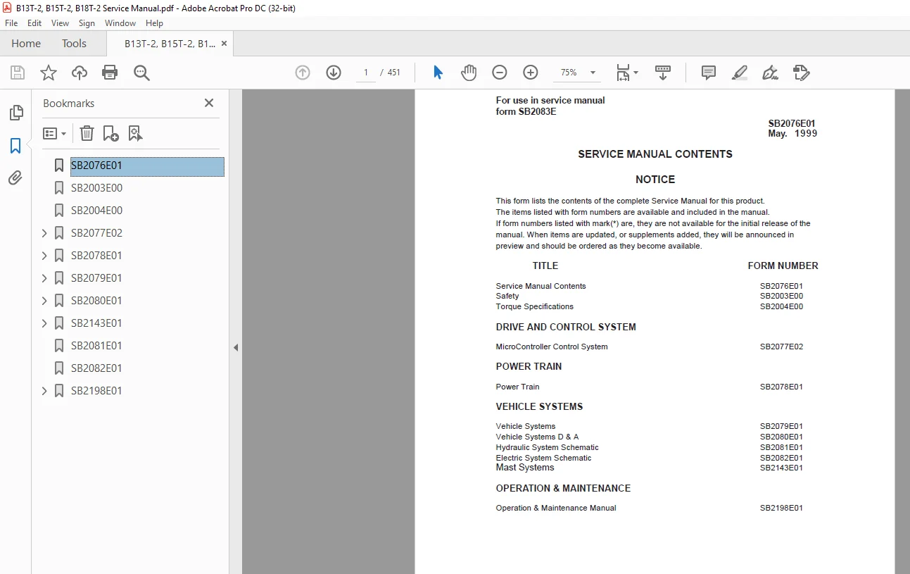
TABLE OF CONTENTS:
Daewoo Doosan Forklift B13T-2 to B18T-2 Service Manuals SB2076E01 – PDF DOWNLOAD
Safety SB2003E00
Torque Specifications SB2004E00
DRIVE AND CONTROL SYSTEM
MicroController Control System SB2077E02
Power Train SB2078E01
Vehicle Systems SB2079E01
Vehicle Systems D & A SB2080E01
Hydraulic System Schematic SB2081E01
Electric System Schematic SB2082E01
Mast Systems SB2143E01
Operation & Maintenance Manual SB2198E01
SB2076E01 1
SB2003E00 3
SB2004E00 5
SB2077E02 13
Index 17
Specifications 19
Component Measurements 19
Console 21
Contactors 22
Control Panel (Layout) 23
Current Measurements 19
Direction Switch 21
Display Layout 21
Fuses 22
Head Capacitor 22
Instrument Panel 21
Thermal Switch – Control Panel 22
Transistor Connections 20
Transistor Measurements 20
Systems Operation 39
Accessory Circuits 39
DC-DC Converter 39
Horn Circuit 39
Hour Meter Circuit 39
Actuation Circuit 40
Drive Circuit 48
Bypass Circuit 53
Control Circuit 48
Current Limit 52
Electrical Braking (Plugging) 54
Failure Protection Circuit 56
Flyback Circuit 51
Power Circuit 49
Thermal Protection Circuits 56
General Information 32
Glossary 25
Hydraulic Pump Motor Circuit 41
Flyback Circuit 45
Lift Circuit 47
Lift Control Circuit 46
Power Steering Circuit 41
Power Steering Idle 42
Location of Control Panel Components 30
Logic Unit 32
Operational Circuit Elements 33
Accelerator Control 38
Battery Discharge Indicator (BDI) 37
Central Vehicle Monitoring System 33
Contactors 36
Current Sensor 36
CVMS International Pictorial Symbols 35
On Board “Run Time” Diagnostics (Fault Detection) 33
Steer Angle Control 38
Wait Mode 36
Symbol Library 29
Testing And Adjusting 61
Built-In Diagnostic Operation 61
Accessing Stored Error Codes 66
Erased Stored Error Codes 66
“Run Time” Diagnostic(Lift Truck in Operation) 61
Quick Diagnostic Procedure 67
Saving Service Records 66
“Self” Diagnostics (Lift Truck not in Operation) 63
Stored Error Codes 67
Component Tests119
Capacitor (Head)122
Conductor and Switch Continuity122
Contactors123
Contactor Components123
Current Sensor125
Diode Replacement126
Diodes126
Driver Board (Off Vehicle)130
Driver Board (On Vehicle)127
Logic Unit Quick Reference Voltage Check119
Resistors (DR1, DR2 and PR1)133
Thermal Switch134
Transistors DTR1,DTR2 and PTR1132
Transistor Replacement DTR1, DTR2 and PTR1132
Control and Power System Operational Checks 60
Electrical System Adjustments135
Accelerator Control Linkage135
BDI Adjustment138
Bypass Dropout Adjustment142
Current Limit Test and Adjustment141
Electrical Braking (Plugging)Current Test and Adjustment142
Lift Sensor136
Parking Brake Switch135
Rapid Tune-Up Procedure138
Tilt and Auxiliary Switches137
Valve Control Card Adjustment136
Preparation Tests and Check 57
Programmable Features143
Activating Default Settings143
Programmable or Settable Option Features144
Setting Procedure Option Features143
System Tests and Adjustments116
Discharging Head Capacitor(HEAD CAP)116
Logics Removal117
“Run Time “Tests117
Test Equipment116
Troubleshooting 57
Troubleshooting Problem List 68
SB2078E01147
Index151
Specifications159
Brake159
Drive Motor155
Final Drive156
General Tightening Torques153
Motor and Transmission158
Wheel Mounting157
Systems Operation161
Drive Motor161
Final Drive162
General Information160
Testing And Adjusting176
Brake176
Connecting the brake cable176
Connecting the hydraulic brake system176
Replenishing With Transmission Fluid177
Drive Motor168
Armature Terminal Test173
Armature Tests169
Brush Holder Test173
Brush Life Estimate174
Commutator Inspection171
Field Coil and Terminal Tests172
Motor Brushes168
Thermal Switch Tests174
Motor and Transmission175
Motor Transmission Unit and Vehicle Frame176
Troubleshooting163
Checks During Operation163
Drive Motor163
Transmission167
Visual Checks163
Disassembly And Assembly178
Drive Axle178
SB2079E01189
Index193
Specifications202
Dual Steer Axle And Wheel202
Hydraulic Control Valve195
Hydraulic Pump196
Hydraulic Pump Motor203
Lift Cylinders197
Standard197
Full Free Triple Lift and Full Free Lift Primary197
Full Free Lift Secondary198
Full Free Triple Lift Secondary198
Priority Valve200
Sideshift Cylinder196
Steer Axle And Wheel202
Steering Gear201
Steering Wheel200
Tilt Cylinder199
Systems Operation217
Brake System217
Master Cylinder217
Electric Motors218
Hydraulic Pump Motor218
Hydraulic System204
Basic Schematic204
Control Valve206
Steering System213
Schematic213
Steering Unit214
Testing and Adjusting234
Brake System234
Brake System Air Removal234
Parking Brake Control Group Adjustment236
Parking Brake Test235
Pedal Adjustment235
Hydraulic Pump Motor236
Armature Tests238
Brush Holder Test241
Brush Life Estimate242
Commutator Inspection239
Field Coil And Terminal Tests240
Motor Brushes236
Thermal Switch(Thermostat) Tests241
Hydraulic System230
Lift Cylinders Air Removal231
Relief Valve Pressure Check230
Steering System232
Steer Wheel Bearing Adjustment232
Steering System Air Removal232
Steering System Pressure Check233
Troubleshooting220
Brake System225
Electric Motors226
Hydraulic System and Mast220
Steering System224
Visual Checks220
SB2080E01243
Index247
Accelerator Control Switch261
Brake Master Cylinder282
Control Panel293
Counterwieght298
Drive Motor & Drive Axle295
Hood(with seat) Assembly249
Hydraulic Control Panel292
Hydraulic Control Valve251
Hydraulic Pump258
Hydraulic Pump Motor257
Overhead Guard250
Primary Lift Cylinder264
Priority Valve281
Secondary Lift Cylinder262
Spindle-Steer Axle289
Steer Axle284
Steer Sensor Group271
Steering Column273
Steering Gear276
Steering Wheel272
Tilt Cylinder267
SB2143E01300
Index304
Disassembly & Assembly306
Forks306
Backrest306
Carriage307
Mast310
Testing & Adjusting323
Carriage Adjustment323
Chain Adjustments324
Chain Wear Test324
Carriage and Mast Height Adjustment325
Forks Parallel Check325
Tilt Cylinder Alignment326
Drift Test326
Tilt Cylinder Adjustment327
Lift & Tilt Mounting Group Adjustment328
Mast mounting Group Adjustment329
SB2081E01330
SB2082E01332
SB2198E01335
Table of Contents337
S.M 18/2/2025