Daewoo Doosan Forklift BC15S, BC18S, BC20SC Electric Lift Trucks MicroController Control System Manual
$28.95
Daewoo Doosan Forklift BC15S, BC18S, BC20SC Electric Lift Trucks MicroController Control System Manual – PDF DOWNLOAD
Description
Daewoo Doosan Forklift BC15S, BC18S, BC20SC Electric Lift Trucks MicroController Control System Manual – PDF DOWNLOAD
FILE DETAILS:
Daewoo Doosan Forklift BC15S, BC18S, BC20SC Electric Lift Trucks MicroController Control System Manual – PDF DOWNLOAD
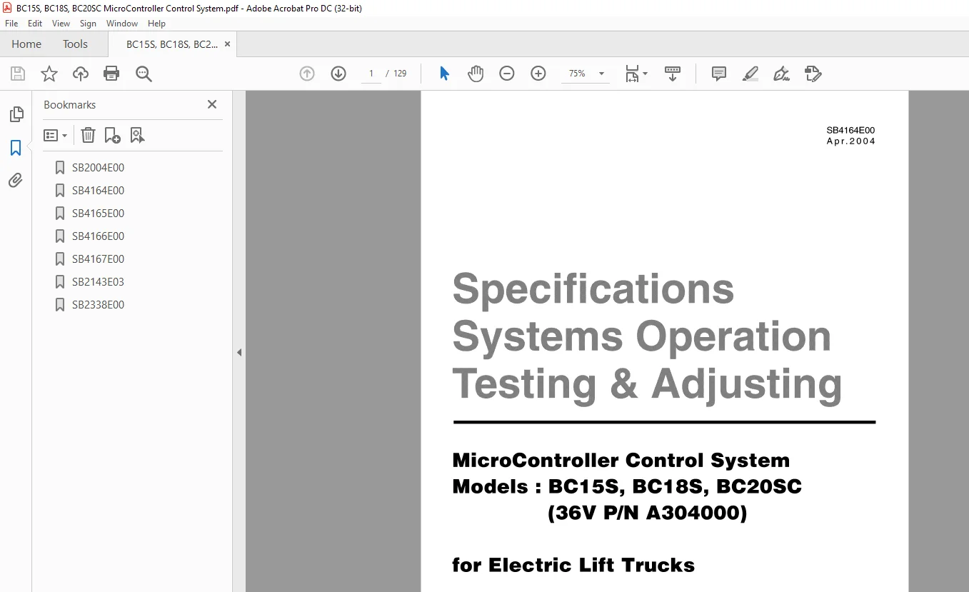
Language :English
Pages :129
Downloadable : Yes
File Type : PDF
IMAGES PREVIEW OF THE MANUAL:
DESCRIPTION:
Daewoo Doosan Forklift BC15S, BC18S, BC20SC Electric Lift Trucks MicroController Control System Manual – PDF DOWNLOAD
Important Safety Information
- Most accidents involving product operation, maintenance and repair are caused by failure to observe basic safety
rules or precautions. An accident can often be avoided by recognizing potentially hazardous situations before an
accident occurs. A person must be alert to potential hazards. This person should also have the necessary
training, skills and tools to perform these functions properly. - Read and understand all safety precautions and warnings before operating or performing lubrication,
maintenance and repair on this product. - Basic safety precautions are listed in the “Safety” section of the Service or Technical Manual. Additional safety
precautions are listed in the “Safety” section of the owner/operation/maintenance publication.
Specific safety warnings for all these publications are provided in the description of operations where hazards
exist. WARNING labels have also been put on the product to provide instructions and to identify specific hazards.
If these hazard warnings are not heeded, bodily injury or death could occur to you or other persons. Warnings in
this publication and on the product labels are identified by the following symbol
TABLE OF CONTENTS:
Daewoo Doosan Forklift BC15S BC18S BC20SC Electric Lift Trucks MicroController Control System Manual – PDF DOWNLOAD
SB2004E00….0
SB4164E00….0
SB4165E00….0
SB4166E00….0
SB4167E00….0
SB2143E03….0
SB2338E00….0
Index
Specifications
Component measurements 5
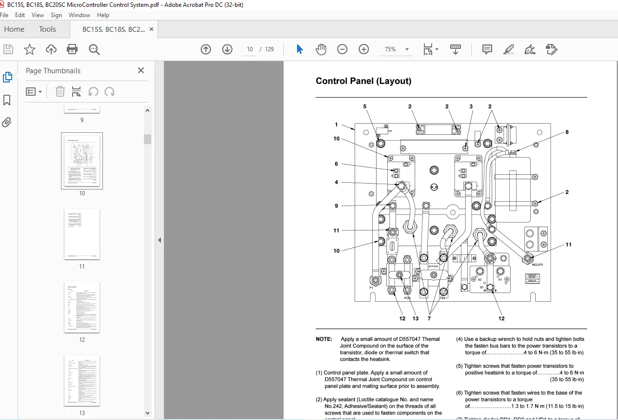
Control Panel (Layout) 9
Current Measurements 5
Transistor Measurements 6
Wait Mode 22
Symbol Library 15
Systems Operation
Glossary 11
Console 7
Contactors 8
Direction Switch 7
Testing And Adjusting
Display Layout 7
Fuses 8
Head Capacitor 8
Instrument Panel 7
Thermal Switch – Control Panel 8
Tip Clearance (Gap) 8
Transistor Connections 6
Electrical System Adjustments 116
Accelerator Control Linkage 116
Activating Default Settings 124
Battery Discharge Indicator (BDI) Adjustment 120
Current Limit Test and Adjustment 122
Electrical Braking (Plugging) Current Test and
Adjustment 123
Lift Sensor 117
Systems Operation Parking Brake Switch 116
Programmable Features 123
Accessory Circuits 25
Actuation Circuit 26
Control Circuit 28
DC-DC Converter 25
Flyback Circuit 32
Horn Circuit 25
Programmable or Settable Option Features 125
Quick Procedure for Programmable Features 124
Rapid Tune-Up Procedure 119
Setting Procedure Option Features 123
Tilt and Auxiliary Switches 118
Valve Control Card Adjustment 117
Hour Meter Circuit 25
Hydraulic Pump Motor Circuit 27
Preparation Tests and Checks 40
Power Circuit 29
Accessing Stored Error Codes 48
Battery Load Test 41
Behind Logic Unit 17
Battery Maintenance 41
General Information 18
Battery Tests 40
Logic Unit 18
Built-In Diagnostic Operation 44
Cell Voltage Test 41
Drive Circuit 33
Control and Power System Operational Checks 43
Bypass Circuit 38
Erased Stored Error Codes 49
Control Circuit 33
Hydrometer Test 41
Current Limit 37
Quick Diagnostic Procedure 49
Failure Protection Circuit 39
Removal of Shorts to Chassis 42
Flyback Circuit 36
Resistance to Chassis Checks 42
Power Circuit 34
“Run Time” Diagnostics (Lift Truck in Operation) 44
Thermal Protection Circuits 39
Saving Service Records 48
“Self” Diagnostics (Lift Truck not in Operation) 45
Location of Control Panel Components 16
Stored Error Codes 49
Visual Checks 42
Operational Circuit Elements 19
Accelerator Control 24
Battery Discharge Indicator (BDI) 23
Central Vehicle Monitoring System (CVMS)
International Pictorial Symbols 21
Central Vehicle Monitoring System 19
Contactors 22
Current Sensor 22
On Board “Run Time” Diagnostics (Fault Detection)
19
System Tests and Adjustments 98
Capacitor (Head) 104
Component Tests 101
Conductor and Switch Continuity 104
Contactor Components 105
Contactors 105
Current Sensor 107
Diode Replacement 108
Diodes 108
MicroController Control System 3 Index
Discharging Head Capacitor (HEAD CAP) 98
Driver Board (Off Vehicle) 111
Driver Board (On Vehicle) 109
Logic Unit Quick Reference Voltage Check 101
Logics Removal 99
Resistors (PR1 and PR2) 114
“Run Time” Tests 99
Test Equipment 98
Thermal Switch 115
Transistor Replacement DTR1 and HTR1 113
Transistors DTR1 and HTR1 113
Troubleshooting 40
Troubleshooting Check List 40
Troubleshooting Problem List 50
MicroController
S.M 19 /2/2025