
Daewoo Doosan D20S-3 – D33S-3 Forklift Repair Manual PDF Download
$30.95
Daewoo Doosan Forklift D20S-3 – D33S-3 Service Manual – PDF DOWNLOAD
Description
Daewoo Doosan Forklift D20S-3 – D33S-3 Service Manual – PDF DOWNLOAD
FILE DETAILS:
Daewoo Doosan Forklift D20S-3 – D33S-3 Service Manual – PDF DOWNLOAD
Size : 129 MB
Format : PDF
Language : English
Brand: Daewoo Doosan
Type of machine: Forklift
Type of document: Service Manual
Model : Daewoo Doosan Forklift
D20S-3(B3.3), D25S-3(B3.3), D30S-3(B3.3), D32S-3(B3.3), D33S-3(B3.3)
Number of Pages: 615 Pages
Part Number: SB4134E00
IMAGES PREVIEW OF THE MANUAL:
DESCRIPTION:
Daewoo Doosan Forklift D20S-3 – D33S-3 Service Manual – PDF DOWNLOAD
Important Safety Information
Most accidents involving product operation, maintenance and repair are caused by failure to observe basic safety
rules or precautions. An accident can often be avoided by recognizing potentially hazardous situations before an
accident occurs. A person must be alert to potential hazards. This person should also have the necessary training,
skills and tools to perform these functions properly.
Read and understand all safety precautions and warnings before operating or performing lubrication,
maintenance and repair on this product.
Basic safety precautions are listed in the “Safety” section or the Service or Technical Manual. Additional safety
precautions are listed in the “Safety” section of the owner/operation/maintenance publication.
Specific safety warnings for all these publications are provided in the description of operations where hazards exist.
WARNING labels have also been put on the product to provide instructions and to identify specific hazards. If
these hazard warnings are not heeded, bodily injury or death could occur to you or other persons. Warnings in this
publication and on the product labels are identified by the following symbol.
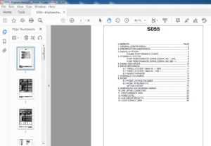
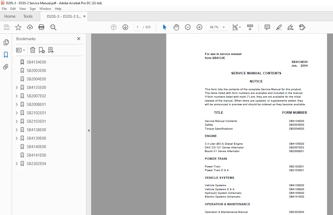
TABLE OF CONTENTS:
Daewoo Doosan Forklift D20S-3 – D33S-3 Service Manual – PDF DOWNLOAD
SB4134E00 1
SB2003E00 3
SB2004E00 5
SB4135E00 13
Index 17
Introduction 18
About the Manual 18
How to Use the Manual 18
Illustrations 20
Symbols 19
Engine Identification 21
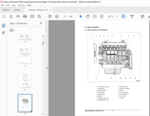
Engine Diagrams 23
Engine Views 23
Engine Identification 21
Engine Dataplate 21
Specifications 22
Troubleshooting Symptoms 34
Procedures and Techniques 34
Troubleshooting Symptoms Charts 34
Coolant Contamination 48
Coolant Loss 49
Coolant Temperature above Normal 52
Engine Cranks But Will Not Start (No Exhaust Smoke) 36
Engine Difficult to Start or Will Not Start (Exhaust Smoke) (Continued) 38
Engine Difficult to Start or Will Not Start (Exhaust Smoke) 37
Engine Has Poor Respones 39
Engine Power Output Low (Continued) 43
Engine Power Output Low 42
Engine Runs Rough or Misfires 41
Engine Stops During Operation 40
Engine Vibration Excessive 55
Engine Will Not Crank or Cranks Slowly 35
Excessive Exhaust (Black Smoke) 44
Excessive Noise (Continued) 54
Excessive Noise 53
Fuel consumption Is Excessive 47
Lubricating Oil Consumption Excessive 45
Lubricating Oil Contaminated 46
Lubricating Oil Pressure Is Low 50
Oil Level Rises 51
Complete Engine 56
Complete Engine 56
Engine Assembly 75
Engine Disassembly 56
Engine Testing101
Complete Engine 103
Measuring Compression Pressure 103
Testing and Adjusting the Fan Belt Tansion 105
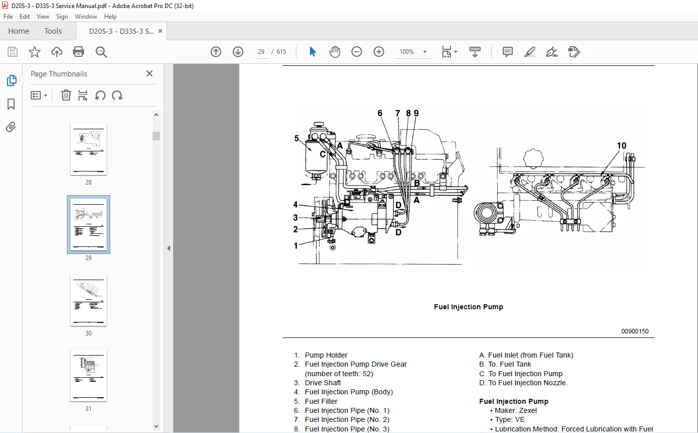
Fuel System 106
Checking and Adjusting Fuel Injection Timing 106
Injector 109
Assembly 112
Disassembly 111
Testing 109
Lubricating System 114
Measuring Oil Pressure 114
Rocker Levers 101
Adjusting Valve Clearance 101
Specifications115
Camshaft and Camshaft Bushing 119
Capscrew Markings and Torque Values – Metric 129
Capscrew Markings and Torque Values – US Customary 130
Capscrew Markings and Torque Values129
Connecting Rod, Piston Ring and Piston Pin 125
Crankshaft 120
Cylinder Block 118
Cylinder Head 117
Cylinder 123
Flywheel 122
Fraction, Decimal, Millimeter Conversions 131
Newton-Meter to Foot-Pound Conversion Chart 132
Oil Pump 126
Pipe Plug Torque Values 132
Piston 124
Regulator Valve 127
Rocker Arm Shaft, Push Rod and Tappets 116
Tap-Drill Chart – US Customary and Metric 133
Thermostat 128
Timing Gear 121
Valves, Valve Guides, and Springs 115
Weight and Measures – Conversion Factors 134
Special Tools 135
Special Tools List135
SB2007E02141
Index145
Specifications 147
Alternator147
Systems Operation148
Alternator148
CS-121 Alternator Operation 148
Alternator Components149
Alternator Operation Schematic151
Introduction148
Testing And Adjusting152
Alternator153
Alternator Output Test153
Machine Test153
Troubleshooting152
Troubleshooting Problem List152
Troubleshooting Problems152
SB2008E01155
Index159
Specifications161
Alternator161
Systems Operation163
Alternator163
Alternator Operation163
Alternator Components163
Alternator Operation Schematics165
Regulator Operation 169
Introduction163
Testing And Adjusting171
Alternator Component Tests173
Brush Tests177
Capacitor Test174
Rectifier Tests176
Regulator Test173
Rotor Field Winding Tests175
Stator Tests175
Alternator Output Test172
Bench Test173
Machine Test172
Troubleshooting171
Troubleshooting Problem List171
Troubleshooting Problems171
Disassembly and Assembly178
Alternator178
Assemble Alternator180
Disassemble Alternator178
SB2102E01182
Index186
Specifications188
Drive Axle Mounting Group197
Drive Tire Installation195
Drive Wheel Installation196
Final Drives And Wheels194
Forward / Reverse Clutch Elements189
Forward And Reverse Control Group188
Tightening Torques192
Torque Converter188
Transmission Solenoid188
Valve Block Elements190
Valve Spring in Transmission Bearing Plate191
Systems Operation198
General Information198
Transmission and Drive Axle199
Basic Control Schematic217
Drive Axle204
Hydraulic System207
Torque Converter199
Transmission200
Transmission Hydraulic System208
Testing And Adjusting221
Troubleshooting221
Check List During Operation222
Check List From Operation Noises223
Check List From Pressure Tests224
Visual Checks221
Transmission and Drive Axle Tests And Adjustments227
Adjustment of Crown Wheel241
Adjustment of Wheel Bearings243
Adjustments on Drive axle and Transmission238
Converter Stall Test229
Electric Control System Tests233
Inching Pedal Adjustment236
Installation of Pinion240
Maintenance Transmission and Drive Axle231
Transmission Pressure Tests227
SB2103E01244
Index248
Transmission250
Assembly Input Shaft261
Assembly Output Shaft264
Assembly Reverse Shaft256
Assembly Transmission Housing265
Disassembly/Assembly Valve Body271
Disassembly Input Shaft259
Disassembly Output Shaft264
Disassembly Reverse Shaft254
Disassembly Transmission Housing250
Drive Axle272
Adjustment Bevel Pinion282
Adjustment Disassembly/Assembly of Bevel Pinion 284
Assembly Bevel Pinion284
Assembly Carrier Diff290
Assembly Crown wheel/Adjustment287
Assembly Shaft As276
Disassembly/Assembly Brake Parts277
Disassembly/Assembly Differential285
Disassembly/Assembly Hub Drive Axle278
Disassembly Differential Assembly279
Disassembly Axle272
Disassembly Bevel Pinion280
Disassembly Shaft As276
Special Service Tools296
SB4138E00298
Index302
Specifications304
Carriage308
Hydraulic Control Valve304
Hydraulic Pump305
Lift & Tilt Mounting Group312
Lift Cylinders305
Lift Relay Group – Standard Lift309
Lift Relay Group – Full Free Lift310
Lift Relay Group – Full Free Triple Lift 311
Mast308
Oil Cooled Disc Brakes316
Parking Brake317
Steer Axle and Wheel315
Steer System Check Valve315
Steer Wheel Mounting316
Steering Gear314
Steering Wheel313
Tilt Cylinders307
Systems Operation318
Brake System330
Brake Valve330
Oil Cooled Disc Brakes331
Parking Brake331
Hydraulic System318
Basic Schematic – Standard Lift318
Basic Schematic – Full Free Lift or Full Free Triple Lift320
Hydraulic Control Valve322
Steering System326
Hydraulic Operation326
Steering Cylinder327
Steering Gear328
Testing and Adjusting332
Brake System357
Brake System Air Removal357
Parking Brake Test357
Parking Brake Adjustment358
Hydraulic System340
Flow Control Valve Adjustment341
Relief Valve Pressure Check340
Standard Lift Cylinder Air Removal342
Mast and Carriage343
Carriage Adjustment348
Carriage and Mast Height Adjustment351
Chain Adjustments349
Chain Wear Test350
Drift Test353
Forks Parallel Check351
Mast Adjustment343
Tilt Cylinder Alignment352
Steering System354
Steer Wheel Bearing Adjustment354
Steering Axle Stop Adjustment355
Steering Knuckle Bearing Preload Adjustment355
Steering System Pressure Check356
Troubleshooting332
Brake System338
Brake Valve337
Hydraulic System and Mast333
Performance Tests332
Steering System336
Visual Checks332
SB4139E00359
Index363
Backrest367
Brake Valve414
Carriage367
Counterweight431
Creeper And Brake Control429
Drive Axle432
Engine438
Forks367
Hood (with seat) Assembly365
Hydraulic Control Valves425
Hydraulic Pump (with Priority Valve) 399
Mast373
Overhead Guard366
Primary Lift Cylinder392
Secondary Lift Cylinders389
Standard Lift Cylinders386
Steer Axle420
Steer Wheels & Bearings416
Steering Cylinder422
Steering Knuckles, Kingpins, And Bearings419
Steering Unit404
Steering Wheel403
Tie Rods418
Tilt Cylinders395
Transmission434
Universal Joint430
SB4140E00443
SB4141E00446
SB2302E04448
Table of Contents450
Information Section451
Foreword451
Safety Section453
Important Safety Information453
Safety454
Warning Signs and Labels454
General Hazard Information458
Operation Information459
Maintenance Information462
Operator Restraint System(If Equipped)465
Avoiding Lift Truck Tipovers469
Safety Rules471
How to Survive in a Tipover476
General Section477
Specifications477
Noise and Vibration489
Capacity Chart490
Serial Number500
Operator’s Warning, and Identification Plate502
Operation Section504
Operator’s Station and Monitoring Systems504
Lift Truck Controls508
Refueling511
Before Starting the Engine514
Starting the Engine517
Dual Fuel System520
After Starting the Engine522
Lift Truck Operation523
Auto Shift Controller ASC-100 (If Equipped)526
Operating Techniques529
Parking the Lift Truck533
Lift Fork Adjustment534
Storage Information535
Transportation Hints536
Towing Information537
Maintenance Section538
Inspection, Maintenance and Repair of Lift Truck Forks538
Tire Inflation Information542
Torque Specifications543
Cooling System Specifications545
Fuel Specifications547
Lubricant Information549
Lubricant Viscosities and Refill Capacities551
Maintenance Intervals552
Quick Reference to Maintenance Schedule554
When Required556
Every 10 Service Hours or Daily564
First 50 – 100 Service Hours or a Week569
First 250 Service Hours or a Month574
Every 250 Service Hours or Monthly575
Every 500 Service Hours or 3 Months582
Every 1000 Service Hours or 6 Months589
Every 2000 Service Hours or Yearly597
Every 2500 Service Hours or 15 Months608
Every 3000 Service Hours or 18 Months609
Environment Protection Section610
Environment Protection610
Index Section611
Index611
Worldwide Network615
S.M 20/2/2025