Daewoo Doosan Forklift D20S-3 to GC30P-3 Service Manuals SB2101E02 – PDF DOWNLOAD
$34.95
Daewoo Doosan Forklift D20S-3 to GC30P-3 Service Manuals SB2101E02 – PDF DOWNLOAD
Models ; D20S-3, D25S-3, D30S-3
G(C)20E-3, G(C)25E-3, GC30E-3
G(C)20P-3, G(C)25P-3, G(C)30P-3
Description
Daewoo Doosan Forklift D20S-3 to GC30P-3 Service Manuals SB2101E02 – PDF DOWNLOAD
FILE DETAILS:
Daewoo Doosan Forklift D20S-3 to GC30P-3 Service Manuals SB2101E02 – PDF DOWNLOAD
Language :English
Pages :1021
Downloadable : Yes
File Type : PDF
IMAGES PREVIEW OF THE MANUAL:
DESCRIPTION:
Daewoo Doosan Forklift D20S-3 to GC30P-3 Service Manuals SB2101E02 – PDF DOWNLOAD
Models ; D20S-3, D25S-3, D30S-3
G(C)20E-3, G(C)25E-3, GC30E-3
G(C)20P-3, G(C)25P-3, G(C)30P-3
SAFETY
Theservicemanormechanicmaybe unfamiliar with many of the systems on this machine. This makes it important to use caution when performing service work. A knowledge of the system and/or components is important before the removal or disassembly of any component. Because of the size of some of the machine components, the serviceman or mechanic should check the weights noted in this Manual, Use proper lifting procedures when removing any components. Following is a list of basic precautions that should always be observed.
Daewoo Doosan Forklift D20S-3 to GC30P-3 Service Manuals SB2101E02 – PDF DOWNLOAD
Models ; D20S-3, D25S-3, D30S-3
G(C)20E-3, G(C)25E-3, GC30E-3
G(C)20P-3, G(C)25P-3, G(C)30P-3
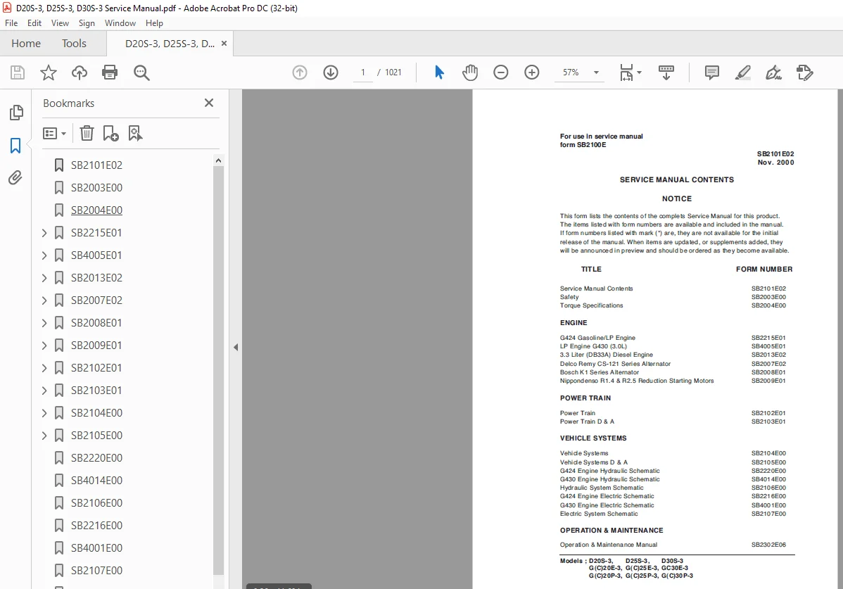
TITLE FORM NUMBER
Service Manual Contents SB2101E02
Safety SB2003E00
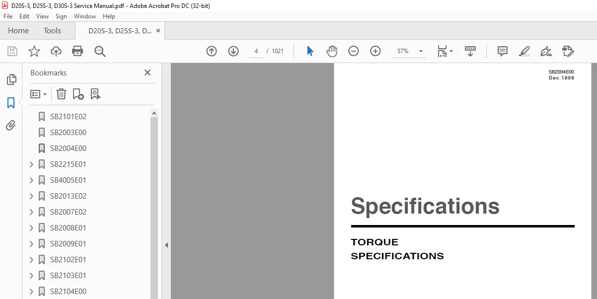
Torque Specifications SB2004E00
ENGINE
G424 Gasoline/LP Engine SB2215E01
LP Engine G430 (3.0L) SB4005E01
3.3 Liter (DB33A) Diesel Engine SB2013E02
Delco Remy CS-121 Series Alternator SB2007E02
Bosch K1 Series Alternator SB2008E01
Nippondenso R1.4 & R2.5 Reduction Starting Motors SB2009E01
POWER TRAIN
Power Train SB2102E01
Power Train D & A SB2103E01
VEHICLE SYSTEMS
Vehicle Systems SB2104E00
Vehicle Systems D & A SB2105E00
G424 Engine Hydraulic Schematic SB2220E00
G430 Engine Hydraulic Schematic SB4014E00
Hydraulic System Schematic SB2106E00
G424 Engine Electric Schematic SB2216E00
G430 Engine Electric Schematic SB4001E00
Electric System Schematic SB2107E00
OPERATION & MAINTENANCE
Operation & Maintenance Manual SB2302E06
SB2101E02 1
SB2003E00 2
SB2004E00 4
SB2215E01 12
Index 14
GENERAL INFORMATION 16
How To Read This Manual 16
Precautions Before Servce 18
General 20
Tightening Torque 21
Sealant 24
SPECIFICATIONS 25
General Specifications 25
Service Specifications 26
MAINTENANCE 29
Test Fuel System for Leaks 29
Check Engine Oil Level 29
Inspect Engine for Fluid Leaks 29
Change Engine Oil &Filter 29
Inspect Accessory Drive Belts 30
Inspect electrical system 30
Inspect Vacuum Lines and Fittings 30
Check Coolant Level 30
Inspect Coolant Hoses 30
Inspect Ignition System 30
Replace Spark Plugs 30
Replace LP Fuel Filter Element 31
Replace Gasoline Fuel Filter (Gasoline Truck and Dual Fuel Truck) 32
Inspect Gasoline Carburetor 32
Inspect Pressure
Regulator/Vaporizer 32
Inspect LP Mixer
(Standard LP Truck) 32
Inspect Variable Venturi
Air/Fuel Mixer
(Low Emission LP Truck) 32
Inspect Complete Exhaust System for Leaks, Damage 32
Engine Control Unit(ECU) and others
(Low Emission LP Truck) 32
Maintenance Schedule 33
ENGINE SYSTEM 34
Engine Overview 34
Timing System 37
Silent Shaft Mechanism 38
Auto Lash Adjuster 39
Intake and Exhaust System 40
Electrical System 42
STARTING SYSTEM 44
General Description 44
Start Relay Tests 47
Starter Motor 48
Operation 48
Removal and Installation 51
Disassembly And Reassembly 54
CHARGING SYSTEM 59
General Description 59
Alternators 59
IGNITION SYSTEM 62
Breakerless Ignition System 62
Distributor 63
Removal and Installation 66
Disassembly and Reassembly 68
GASOLINE FUEL SYSTEM 70
General Description 70
Gasoline Carburetor – Operation 71
Removal and Installation 76
Gasoline Carburetor
Disassembly and Reassembly 78
LP FUEL SYSTEM 85
General Description 85
Electric Fuelock Model 85
Converter 86
Fuel Tank 87
LP Relief Valve 87
Carburetor 88
Tests or Adjustments 89
Carburetor Adjustment 89
Fuel System Leak Check 91
Recommendation For LP Fuel Systems 92
LP Converter – Check, Clean 93
Disassembly & Assembly 94
LPG Carburetor 94
LP Gas Fuelock 96
LP Gas Converter 97
LPG FUEL SYSTEM (LOW EMISSION VERSION) 99
General Description 99
LP Carburetor(Variable Venturi) 101
Vacuum Switch (MAP) 102
Vacuum Switch 102
LP Converter 103
Fuel Control Valve 104
Fuel Lock – Off 104
Engine Control Unit (ECU) 105
Oxygen Sensor 106
Catalytic Muffler 107
Tests or Adjustments 108
LP Carburetor-Check, Clean 108
LP Converter-Check, Clen 109
Inspection of Fuel Lock – Off 109
Inspection of Fuel Control Valve 109
Inspection of Vacuum Switch 109
Inspection of Vacuum Switch (MAP) 109
Inspection of Oxygen Sensor 110
Disassembly & Assembly 111
LPG Carburetor 111
LP Gas Converter 113
DUAL FUEL SYSTEM 114
GOVERNING SYSTEM 115
General Description 115
Air Governor
Disassembly and Reassembly 116
LUBRICATION SYSTEM 118
General Description 118
Testing & Adjusting 119
Engine Oil 119
Lubrication System Problems 119
Oil Pressure Check 121
COOLING SYSTEM 122
General Description 122
Testing & Adjusting 123
Cooling System Visual Inspection 123
Cooling System Tests 123
Thermostat 125
Cooling System Heat Problems 126
Cooling System Recommendation 126
Belt Adjustment 128
V-Belt Diagnosis 128
Service Procedures 129
Draining and Filling the Cooling System 129
Flushing the Cooling System 130
Radiator Service 130
Remove & Install Water
Temperature Sender 131
BASE ENGINE SERVICE PROCEDURE 132
Timing Belt 132
Intake Manifold 141
Exhaust Manifold and Water Pump 142
Rocker Arms And Camshaft 145
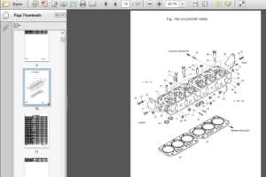
Cylinder Head And Valves 151
Front Case And Oil Pan 157
Piston And Connecting Rod 166
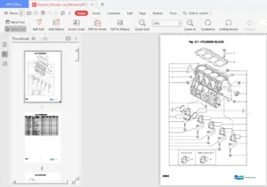
Crankshaft And Cylinder Block 174
ADJUSTING AND TROUBLESHOOTING 181
Adjustment 181
Valve Clearance Adjustment 181
Ingition Timing Adjustment 181
Idling Speed Adjustment 183
Air Governor Adjustment 183
Anti-Hunting Adjustment 183
Troubleshooting 184
Engine Performance 184
Engine Starting Problems 184
Engine Starting Problems (Continued) 185
Charging System Problems 185
Instrument Problems 185
Engine Noise 186
Engine Noise (Continued) 187
Oil Pressure Diagnostics 188
Oil Pressure Problems 189
Water in Engine 190
Engine Overheating 191
LP Fuel System (Standard and/or Low Emission Version) 192
Troubleshooting Flow Chart 199
General 199
Base Engine 201
Carburetor 203
Electrical components 204
SPECIAL TOOLS 207
SB4005E01 211
Index 214
GENERAL INFORMATION 218
Shop Safety 218
Fuel Information 219
What is LPG? 219
13 Air Temperature Versus
Air Temperature Versus Power Output 220
Altitude Versus Power Output 221
General Description General Description & Operation 222
Engine Component Description 222
Lubrication 222
Thread Repair 222
Cleanliness and Care 223
Replacing Engine Gaskets 223
Use of RTV and Anaerobic Sealer 224
Separating Parts 225
Tools and Equipment 225
SPECIFICATIONS 226
Technical Data 226
General Description 226
Fuel System 226
Cooling System 227
Lubrication System 227
Engine Electrical 227
Exhaust System (Low Emission Version Only) 227
Engine Mechanical Data 228
Fastener Tightening Specifications 228
Sealers, Adhesives and Lubricants 228
Engine Mechanical Specifications 229
MAINTENANCE 231
Test fuel system for leaks 231
Inspect engine for fluid leaks 231
Engine Crankcase Oil 231
Oil Recommendations 231
Checking/Filling Engine Oil Level 232
Changing Engine Oil And Filter 232
Accessory Drive Belts 232
Inspect electrical system 232
Inspect vacuum lines and fittings 233
Inspect fuel lines and fittings 233
Engine Compression Check 233
Cooling System 233
Checking coolant Level 233
Inspect coolant hoses 234
Inspect ignition system 234
Replace spark plugs 234
Replace LP Fuel Filter Element 234
Test fuel lock (electric) 235
Inspect pressure regulator/vaproizer 235
Inspect LP mixer(standard LP truck) 235
Inspect variable venturi air/fuel mixer (low emission LP truck) 235
Inspect complete exhaust system for leaks, damage 235
Engine Control Unit (ECU) and others (low emission LP truck) 235
Maintenance Schedule 236
TROUBLESHOOTING 237
Engine Performance 237
Engine Starting Problems 237
Charging System Problems 238
Instrument Problems 238
Engine Noise 239
Oil Pressure Diagnostics 241
Oil Pressure Problems 242
Water in Engine 243
Engine Overheating 244
LP Fuel system (Sandard and/or
Low Emission Version) 245
STARTING SYSTEM 253
General Description 253
Start Relay Tests 256
Starting Motors 257
CHARGING SYSTEM 258
General Description 258
Alternators 258
Remove & Install Alternator 260
IGNITION SYSTEM 261
General Information 261
Conventional Ignition Systems 261
High Energy Ignition Systems 262
Module 263
Pulse Generator 263
Magnetic Flux Path 264
Current Limiting Circuit 264
Dwell Control Circuit 265
Ignition Coil 266
HEl Models 268
Electronic Spark Timing (EST) Distributor 270
Spark Plug Wires 272
Spark Advance Curves 272
Delco Electronic Spark Timing(EST) Distributor Service 273
General Description 273
EST Distributor Component Testing 273
EST Distributor Removal 275
EST Distributor Disassembly 276
EST Distributor Installation(Engine Not Disturbed) 277
EST Distributor Installation(Engine Disturbed) 277
Ignition Timing – EST System 277
LP FUEL SYSTEM 280
General Information 280
Electric Fuelock Models 280
Converter 281
Fuel Tank 282
LP Relief Valve 282
Carburetor 283
Tests or Adjustments 284
Carburetor Adjustment 284
Fuel System Leak Check 286
Recommendation For LPFuel Systems 287
LP Converter – Check, Clean 288
Disassembly & Assembly 289
LP Gas Carburetor 289
LP Gas Fuelock 291
LP Gas Converter 292
LP FUEL SYSTEM (LOW EMISSION VERSION) 294
General Description 294
System Overivew 294
Fuel Lock (Electric) 296
Pressure Regulator/Vaporizer 296
Pressure Regulator Theory of Operation 297
Variable Venturi Air/Fuel Mixer 298
Variable Venturi Air/Fuel Mixer Theory of Operation 299
Catalytic Muffler 300
Engine Control Unit (ECU) 301
Oxygen Sensor 302
Vacuum Switch (MAP) 302
Fuel Control Valve 303
Tests or Adjustments 304
LP Carburetor-Check, Clean 304
LP Converter-Check, Clean 305
Inspection of Fuel Lock Valve 305
Inspection of Fuel Control Valve 305
Inspection of Vacuum Switch(MAP) 306
Inspection of Oxygen Sensor 306
Disassembly & Assembly 307
LP Converter 307
GOVERNOR SYSTEM 308
General Description 308
Governor Operation 309
Adjustment Procedures 310
LUBRICATION SYSTEM 312
General Description 312
Testing & Adjusting 313
Lubrication System Problems 313
Oil Pressure Check 314
COOLING SYSTEM 315
General Description 315
Testing & Adjusting 316
Cooling System Visual Inspection 316
Cooling System Tests 316
Thermostat 318
Cooling System Heat Problems 319
Cooling System Recommendation 319
Belt Adjustment 321
V-Belt Diagnosis 321
Service Procedures 322
Draining and Filling the Cooling System 322
Flushing the Cooling System 323
Radiator Service 323
Thermostat Replacement 324
Water Pump Replacement 325
Remove & Install Water Temperature
Sender 326
BASE ENGINE SERVICE PROCEDURE 327
Disassembled View (1 of 4) 327
Disassembled View (2 Of 4) 328
Disassembled View (3 Of 4) 329
Disassembled View (4 Of 4) 330
Draining Fluids and Oil Filter
Removal 331
Engine Flywheel Removal 332
Distributor Removal 332
Ignition Coil Removal 333
Lift Bracket Removal 333
Spark Plug Removal 333
Intake/Exhaust Manifold Removal 333
Crankshaft Pulley Removal 334
Valve Rocker Arm Cover Removal 334
Pushrod Cover Removal 334
Intake/Exhaust Manifold Disassemble and Assemble 335
Intake/Exhaust Manifold Clean and Inspect 335
Water Pump Removal 336
Valve Rocker Arm and Pushrod Removal 336
Measuring Camshaft Lobe Lift 337
Valve Train Components Inspect(Cylinder Head) 338
Valve Lifter Removal 338
Cylinder Head Removal 339
Oil Pan Removal 339
Oil Pump Removal 339
Oil Level Indicator and Tube Removal 340
Engine Front Cover Removal 340
Measuring Crankshaft and Camshaft Sprocket Runout 341
Measuring Timing Sprocket Teeth Backlash 341
Crankshaft Sprocket Removal 342
Camshaft Removal 342
Crankshaft and Camshaft Sprocket Inspect 342
Timing Gear Oil Nozzle Removal 343
Piston, Connecting Rod and Bearing Removal 343
Crankshaft and Bearings Clean
and Inspect (Connecting Rod
Bearing Clearance) 345
Crankshaft Rear Oil Seal and Housing Removal 347
Crankshaft, Bearings and Bearing Cap Removal 347
Crankshaft and Bearings Clean
and Inspect 348
Crankshaft and Bearings Clean
and Inspect (Main Bearing
Clearance) 350
Camshaft Bearing Removal 352
Distributor Lower Bushing and Thrust Washer Removal 353
Oil Filter Bypass Valve Removal and Installation 353
Cylinder Block Clean and Inspect 354
Cylinder Bore Measurements 354
Cylinder Boring and Honing 355
Distributor Lower Bushing and Thrust Washer Installation 356
Piston and Connecting Rod Disassemble 356
Piston and Connecting Rod
Clean and Inspect 357
Piston Selection 359
Piston and Connecting Rod
Assemble 360
Camshaft and Bearings Clean
and Inspect 361
Camshaft Sprocket and Retainer
Removal and Installation 363
Camshaft Bearing Installation 364
Oil Pump Disassemble 365
Oil Pump Clean and Inspect 366
Oil Pump Assemble 367
Cylinder Head Disassemble 368
Cylinder Head Clean and Inspect 369
Rocker Arm Stud Removal and
Installation 373
Cylinder Head Assemble 374
Crankshaft, Bearings and
Bearing Cap Installation 375
Crankshaft Rear Oil Seal and
Housing Installation 376
Piston, Connecting Rod and
Bearing Installation 377
Timing Gear Oil Nozzle Installation 378
Crankshaft Sprocket Installation 378
Camshaft Installation 379
Engine Front Cover and Oil Seal Installation 379
Oil Pump Installation 380
Oil Pan Installation 380
Crankshaft Pulley Installation 381
Cylinder Head Installation 381
Valve Lifter Installation 382
Valve Rocker Arm and Pushrod
Installation 382
Pushrod Cover Installation 384
Valve Rocker Arm Cover
Installation 384
Oil Level Indicator and Tube Installation 385
Water Pump Installation 385
Intake/Exhaust Manifold Installation 385
Spark Plug Installation 386
Lift Bracket Installation 386
Ignition Coil Installation 386
Distributor Installation 387
Engine Flywheel Installation 387
Engine Block Coolant Plug/Oil
Filter Installation 388
SPECIAL TOOS AND EQUIPMENT 389
SB2013E02 393
CONTENTS 396
1 GENERAL INFORMATION 397
11 General Repair Instructions 397
12 Engine Specifications 398
13 Torque Specifications 399
14 Major Parts Fixing Bolts 400
15 Engine Repair Kit 406
16 Repair 407
2 Engine Assembly 413
21 General Description 413
22 Disassembly 414
23 Inspection and Repair 424
24 Engine Reassembly 440
3 Lubricating System 456
31 General Description 456
32 Oil Pump 456
33 Oil Filter 458
34 Oil Cooler 460
4 Cooling System 461
41 General Description 461
42 Water Pump 461
43 Thermostat 464
5 Fuel System 465
51 General Description 465
52 Fuel Filter 466
53 Injection Nozzle 466
6 Special Tool List 469
SB2007E02 471
Index 474
Specifications 476
Alternator 476
Systems Operation 477
Alternator 477
CS-121 Alternator Operation 477
Alternator Components 478
Alternator Operation Schematic 480
Introduction 477
Testing And Adjusting 481
Alternator 482
Alternator Output Test 482
Machine Test 482
Troubleshooting 481
Troubleshooting Problem List 481
Troubleshooting Problems 481
SB2008E01 484
Index 487
Specifications 489
Alternator 489
Systems Operation 491
Alternator 491
Alternator Operation 491
Alternator Components 491
Alternator Operation Schematics 493
Regulator Operation 497
Introduction 491
Testing And Adjusting 499
Alternator Component Tests 501
Brush Tests 505
Capacitor Test 502
Rectifier Tests 504
Regulator Test 501
Rotor Field Winding Tests 503
Stator Tests 503
Alternator Output Test 500
Bench Test 501
Machine Test 500
Troubleshooting 499
Troubleshooting Problem List 499
Troubleshooting Problems 499
Disassembly and Assembly 506
Alternator 506
Assemble Alternator 508
Disassemble Alternator 506
SB2009E01 510
Index 513
Specification 515
Starting Motor 515
Systems Operation 517
Starting Motor 517
Introduction 517
Starting Motor Operation Diagrams 520
Testing And Adjusting 523
Starting Motor 524
Off Machine No Load Test 527
On Machine Starting Motor Diagnosis Procedure 524
Starting Motor Component Tests 528
Troubleshooting 523
Troubleshooting Problem List 523
Troubleshooting Problems 523
Disassembly And Assembly 533
Starting Motor 533
Assemble Starting Motor 536
Disassemble Starting Motor 533
SB2102E01 540
Index 543
Specifications 545
Drive Axle Mounting Group 554
Drive Tire Installation 552
Drive Wheel Installation 553
Final Drives And Wheels 551
Forward / Reverse Clutch
Elements 546
Forward And Reverse Control
Group 545
Tightening Torques 549
Torque Converter 545
Transmission Solenoid 545
Valve Block Elements
(On top of transmission) 547
Valve Spring in Transmission Bearing Plate 548
Systems Operation 555
Basic Control Schematic 574
Drive Axle 561
Hydraulic System 564
Torque Converter 556
Transmission 557
Transmission Hydraulic System 565
Testing And Adjusting 578
Troubleshooting 578
Check List During Operation 579
Check List From Operation Noises 580
Check List From Pressure Tests 581
Visual Checks 578
Transmission and Drive Axle Tests And Adjustments 584
Adjustment of Crown Wheel 598
Adjustment of Wheel Bearings 600
Adjustments on Drive axle and Transmission 595
Converter Stall Test 586
Electric Control System Tests 590
Inching Pedal Adjustment 593
Installation of Pinion 597
Maintenance Transmission and Drive Axle 588
Transmission Pressure Tests 584
SB2103E01 601
Index 604
Transmission 606
Assembly Input Shaft 617
Assembly Output Shaft 620
Assembly Reverse Shaft 612
Assembly Transmission Housing 621
Disassembly/Assembly Hub Drive Axle 634
Disassembly Input Shaft 615
Disassembly Output Shaft 620
Disassembly Reverse Shaft 610
Disassembly Transmission Housing 606
Drive Axle 628
Adjustment Bevel Pinion 638
Adjustment Disassembly/Assembly of
Bevel Pinion 640
Assembly Bevel Pinion 640
Assembly Carrier Diff 646
Assembly Crown wheel/Adjustment 643
Assembly Shaft As 632
Disassembly/Assembly Brake Parts 633
Disassembly/Assembly Differential 641
Disassembly/Assembly Hub Drive Axle 634
Disassembly Differential Assembly 635
Disassembly Axle 628
Disassembly Bevel Pinion 636
Disassembly Shaft As 632
Special Service Tools 652
SB2104E00 654
Index 657
Specifications 659
Carriage 663
Hydraulic Control Valve 659
Hydraulic Pump 660
Lift & Tilt Mounting Group 667
Lift Cylinders 660
Lift Relay Group – Standard Lift 664
Lift Relay Group – Full Free Lift 665
Lift Relay Group – Full Free Triple Lift 666
Mast 663
Oil Cooled Disc Brakes 672
Parking Brake 672
Priority Valve 668
Steer Axle and Wheel 670
Steer System Check Valve 670
Steer Tire Installation 671
Steer Wheel Mounting 671
Steering Gear 669
Steering Wheel 668
Tilt Cylinders 662
Systems Operation 673
Brake System 685
Brake Valve 685
Oil Cooled Disc Brakes 686
Parking Brake 686
Hydraulic System 673
Basic Schematic – Standard Lift 673
Basic Schematic – Full Free Lift or Full Free Triple Lift 675
Hydraulic Control Valve 677
Steering System 681
Hydraulic Operation 681
Steering Cylinder 682
Steering Gear 683
Testing and Adjusting 687
Brake System 712
Brake System Air Removal 712
Parking Brake Test 712
Parking Brake Adjustment 713
Hydraulic System 695
Flow Control Valve Adjustment 696
Relief Valve Pressure Check 695
Standard Lift Cylinder Air Removal 697
Mast and Carriage 698
Carriage Adjustment 703
Carriage and Mast Height Adjustment 706
Chain Adjustments 704
Chain Wear Test 705
Drift Test 708
Forks Parallel Check 706
Mast Adjustment 698
Tilt Cylinder Alignment 707
Steering System 709
Steer Wheel Bearing Adjustment 709
Steering Axle Stop Adjustment 710
Steering Knuckle Bearing Preload Adjustment 710
Steering System Pressure Check 711
Troubleshooting 687
Brake System (Oil Cooled Disc Type) 693
Brake Valve 692
Hydraulic System and Mast 688
Performance Tests 687
Steering System 691
Visual Checks 687
SB2105E00 714
Index 717
Backrest 721
Brake Valve 768
Carriage 721
Counterweight 786
Creeper And Brake Control 784
Drive Axle 787
Engine 793
Forks 721
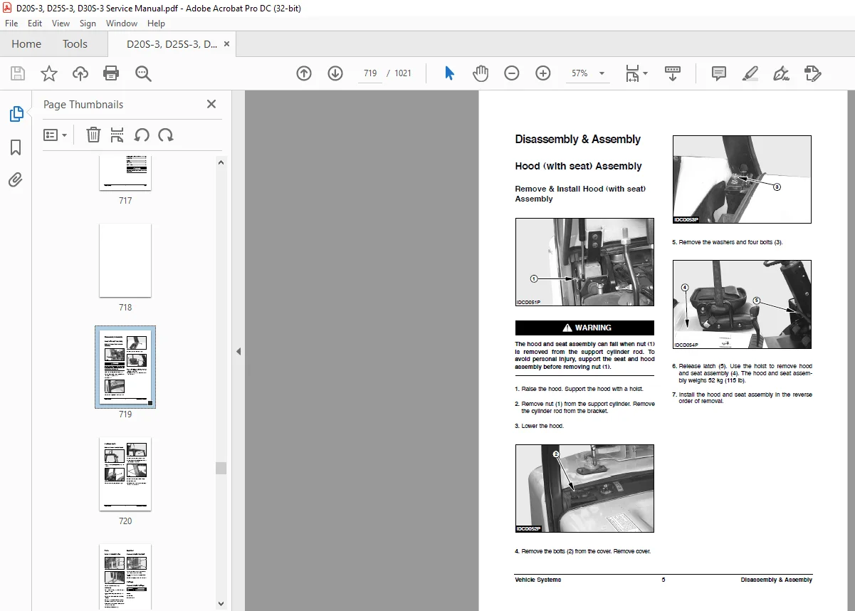
Hood (with seat) Assembly 719
Hydraulic Control Valves 780
Hydraulic Pump (with Priority Valve) 753
Mast 727
Overhead Guard 720
Primary Lift Cylinder 746
Secondary Lift Cylinders 743
Standard Lift Cylinders 740
Steer Axle 774
Steer Wheels & Bearings 770
Steering Cylinder 776
Steering Knuckles, Kingpins, And Bearings 773
Steering Unit 758
Steering Wheel 757
Tie Rods 772
Tilt Cylinders 749
Transmission 789
Universal Joint 785
SB2220E00 798
SB4014E00 800
SB2106E00 803
SB2216E00 805
SB4001E00 809
SB2107E00 813
SB2302E06 817
Table of Contents 819
Information Section 820
Foreword 820
Literature Information 820
Safety Section 822
Important Safety Information
available 822
Safety 823
Warning Signs and Labels 823
Parking brake 827
General Hazard Information 828
Operation Information 829
Maintenance Information 832
Operator Restraint System(If
Equipped) 835
Avoiding Lift Truck Tipover 839
Safety Rules 841
How to Survive in a Tipover 846
General Section 848
Specifications 848
Noise and Vibration 868
Capacity Chart 869
Serial Number 879
Operator’s Warning and Identification Plate 882
Operation Section 883
Operator’s Station and Monitoring Systems 883
Lift Truck Controls 887
Refueling 890
Before Starting the Engine 893
Starting the Engine 896
Dual Fuel System (If G424 Dual Fuel Engine Equipped) 899
Dual Fuel System (G424E/G430E Engine Only) 901
Lift Truck Operation 904
G424E/G430E Electronic Controlled LP and Dual Fuel Engines(If Equipped) 907
Advanced Diagnostics 922
Table a MI-04 Diagnostic Fault Codes (Flash Codes) 924
Auto Shift Controller ASC-100 (If Equipped) 930
Operating Techniques 933
Parking the Lift Truck 937
Lift Fork Adjustment 938
Storage Information 939
Transportation Hints 940
Towing Information 941
Maintenance Section 942
Inspection, Maintenance and Repair of Lift Truck Forks 942
Tire Inflation Information 946
Torque Specifications 947
Cooling System Specifications 949
Fuel Specifications 951
Lubricant Information 953
Lubricant Viscosities and Refill Capacities 955
Maintenance Intervals 956
When Required 960
Every 10 Service Hours or Daily 970
First 50 – 100 Service Hours or a Week 975
First 250 Service Hours or a Month 980
Every 250 Service Hours or Monthly 981
Every 500 Service Hours or 3 Months 988
Every 1000 Service Hours or 6 Months 997
Every 1500 Service Hours or 9 Months1003
Every 2000 Service Hours or Yearly1006
Every 2500 Service Hours or 15 Months1013
Every 3000 Service Hours or 18 Months1016
Every 4500 Service Hours or two Years1017
Index Section1018
Index1018
S.M 18/2/2025