Daewoo Doosan Forklift GC15S-2, GC18S-2, GC20SC-2 Service Manuals SB4007E01A – PDF DOWNLOAD
$31.95
Daewoo Doosan Forklift GC15S-2, GC18S-2, GC20SC-2 Service Manuals SB4007E01A – PDF DOWNLOAD
Description
Daewoo Doosan Forklift GC15S-2, GC18S-2, GC20SC-2 Service Manuals SB4007E01A – PDF DOWNLOAD
FILE DETAILS:
Daewoo Doosan Forklift GC15S-2, GC18S-2, GC20SC-2 Service Manuals SB4007E01A – PDF DOWNLOAD
Language :English
Pages :622
Downloadable : Yes
File Type : PDF
IMAGES PREVIEW OF THE MANUAL:
DESCRIPTION:
Daewoo Doosan Forklift GC15S-2, GC18S-2, GC20SC-2 Service Manuals SB4007E01A – PDF DOWNLOAD
SAFETY
- The serviceman or mechanic may be unfamiliar with many of the systems on this machine. This makes it important to use caution when performing service work. A knowledge of the system and/or components is important before the removal or disassembly of any component.
- Because of the size of some of the machine components, the serviceman or mechanic should check the weights noted in this Manual, Use proper lifting procedures when removing any components.
- Because of the size of some of the machine components, the serviceman or mechanic should check the weights noted in this Manual, Use proper lifting procedures when removing any components.
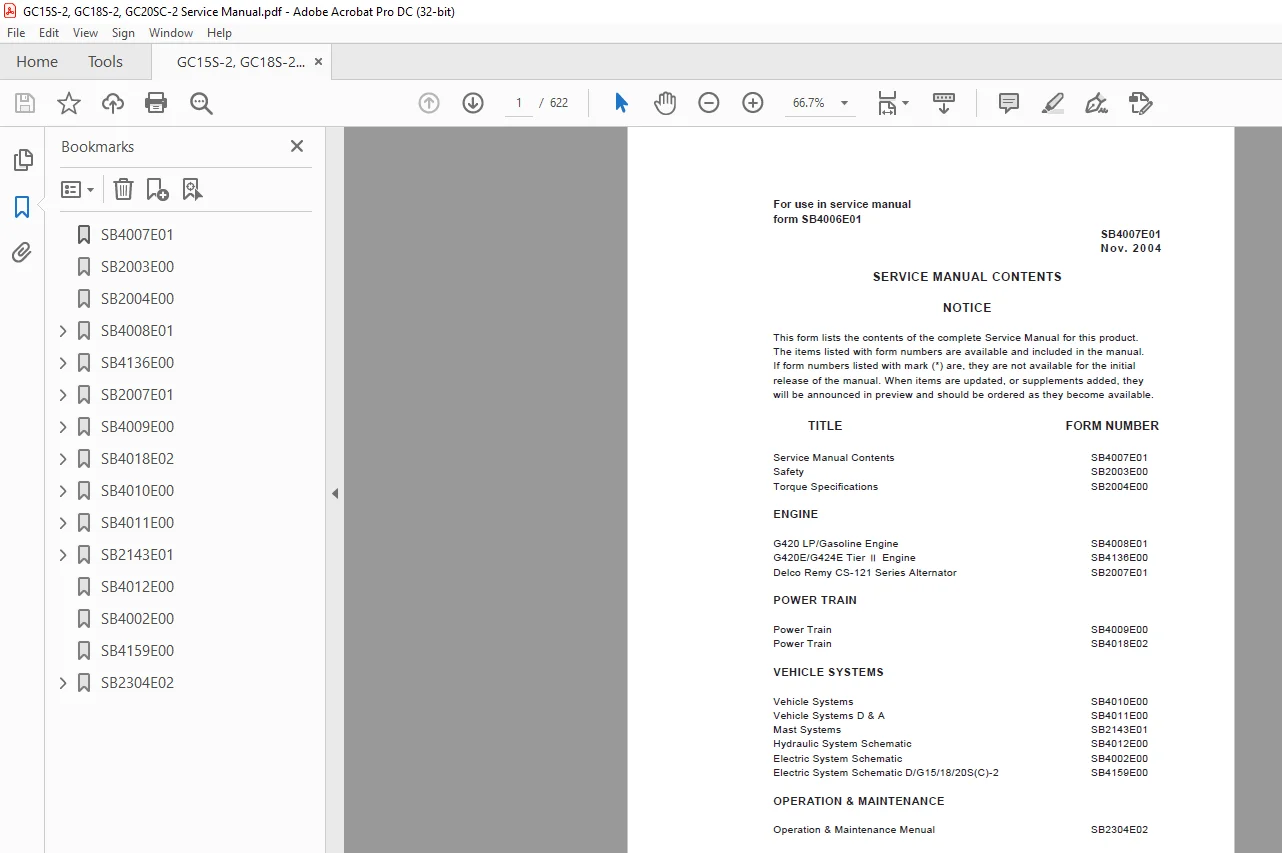
TABLE OF CONTENTS:
Daewoo Doosan Forklift GC15S-2, GC18S-2, GC20SC-2 Service Manuals SB4007E01A – PDF DOWNLOAD
SB4007E01 1
SB2003E00 2
SB2004E00 4
SB4008E01 12
INDEX 15
General Information 16
General 20
How To Read This Manual 16
Precautions Before Servce 18
Sealant 24
Tightening Torque 21
Specification 25
General Specifications 25
Service Specifications 26
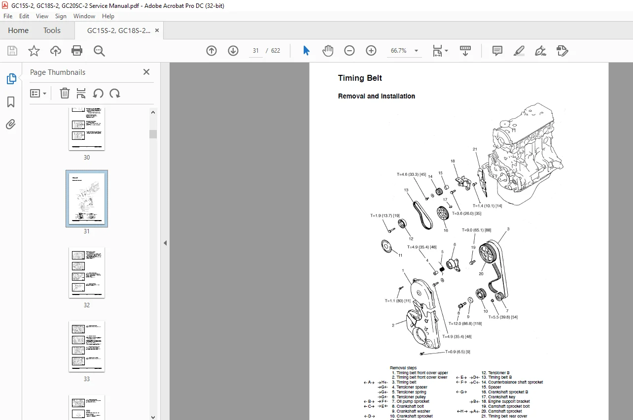
Removal and Installation 29
Air Governor 90
Carburetor 83
Crankshaft And Cylinder Block 76
Cylinder Head And Valves 53
Distributor100
Exhaust Manifold and Water Pump 45
Front Case And Oil Pan 59
Fuel System 40
Ignition System 29
Intake Manifold 43
Piston And Connecting Rod 68
Rocker Arms And Camshaft 47
Starter Motor 92
Timing Belt 31
System Operation102
Engine102
Lubrication System107
Fuel System108
Cooling System117
Intake and Exhaust System118
Electrical System119
Adjust And Trouble Shooting125
Engine Adjustment125
Troubleshooting127
SPECIAL TOOLS135
SPECIAL TOOLS135
SB4136E00138
Index143
WORKING WITH LPG
EQUIPMENT 145
CHAPTER 0 LPG AND LPG FUEL TANKS146
LPG Fuel Supply146
LPG Fuel Tanks147
Installing LPG Fuel Tanks147
LPG Fuel Tank Components148
Fuel Gauge148
Service Valve148
Quick Disconnect Coupling149
Filler Valve149
CHAPTER 1 ENGINE SPECIFICATION150
Indication of Engine Serial Number150
Specifications(G420E)151
Specifications(G424E)152
CHAPTER 2 MI-04 LPG SYSTEM OPERATIONAL
OVERVIEW153
MI-04 General Description153
MI-04 LP Fuel Filter155
MI-04 Fuel Lock-Off (Electric)155
MI-04 N-2001
Regulator/Converter 156
N-2001 Theory of Operation157
MI-04 N-CA55-500TR Mixer158
N-CA55-500-TR Air/Fuel Mixer Theory of Operation158
MI-04 Electronic Throttle160
MI-04 Fuel Trim Valve161
Heated Exhaust Gas Oxygen Sensor (HEGO)162
MI-04 SECM
(General Description)163
MI-04 SECM
(Fuel Management)163
MI-04 SECM (Load/Speed Management)165
MI-04 Ignition management167
CHAPTER 3 MI- 04 MAINTENANCE SCHEDULE168
RECOMMENDED
MAINTENANCE SCHEDULE168
Test Fuel System for Leaks168
Inspect Engine for Fluid
Leaks168
Inspect Vacuum Lines and
Fittings168
Inspect Electrical System168
Inspect Acceleration Pedal
Operation169
Check Coolant Level169
Inspect Coolant Hoses169
Inspect Battery System169
Inspect Ignition System169
Replace Spark Plugs169
Replace LP Fuel Filter Element170
Testing Fuel Lock-off
Operation171
Pressure
Regulator/Converter Testing
and Inspection171
Fuel Trim Valve Inspection
(FTV)171
Inspect Air/Fuel Valve Mixer
Assembly171
Inspect for Intake Leaks172
Inspect Throttle Assembly172
Checking the TMAP Sensor172
Inspect Engine for Exhaust
Leaks172
Maintenance Schedule173
CHAPTER 4 MI-04 LP BASIC TROUBLESHOOTING175
Basic Troubleshooting175
CHAPTER 5 MI-04 LP ADVANCED DIAGNOSTICS182
Advanced Diagnostics182
Reading Diagnostic Fault Codes182
Displaying Fault Codes (DFC) From SECM Memory183
Clearing Fault (DFC) Codes183
Fault Action Descriptions183
Fault List Definitions184
Table a MI-04 Diagnostic Fault Codes (Flash Codes)186
CHAPTER 6 MI-04 ELECTRICAL CONNECTIONS198
Resistance Checks200
Voltage Checks201
CHAPTER 7 N2001 PRESSURE REGULATOR
/CONVERTER202
Removal and Installation of
N2001 LP
Regulator/Converter202
Hose Connections203
N2001 Removal Steps:204
N2001 Regulator
Disassembly Steps:205
N2001 Disassembled Service207
CHAPTER 8 N-CA55-500TR AIR/FUEL MIXER208
Removal and Installation of
the N-CA55-500TR Mixer208
N-CA55-500TR Mixer
Removal Steps:209
N-CA55-500TR Disassembly
and Service210
N-CA55-500TR Disassembled
Service212
Installing the
Mixer/Throttle Assembly213
CHAPTER 9 TEST AND ADJUSTMENTS216
N2001 Service Testing216
Primary Stage Test Hardware217
Primary Stage Pressure Test217
N-CA55-500TR Service AVV (Air Valve Vacuum) Testing219
Ignition Timing Adjustment220
Idle Mixture Adjustment223
CHAPTER 10 SERVICE TOOL KIT225
Service Tool Kit225
SB2007E01226
INDEX229
Specifications231
Alternator231
Systems Operation232
Alternator232
CS-121 Alternator Operation232
Alternator Components233
Alternator Operation Schematic235
Introduction232
Testing And Adjusting 236
Alternator237
Alternator Output Test237
Machine Test237
Troubleshooting236
Troubleshooting Problem List236
Troubleshooting Problems236
SB4009E00239
INDEX242
Specification246
Final Drives And Wheels246
Torque Converter244
Transmission245
Wheel Bearing Adjustment247
Systems Operation261
Differential And Drive Axles261
General Information248
Torque Converter249
Transmission General Information251
Transmission Hydraulic System253
Transmission Power Flows252
Testing And Adjusting265
Transmission Tests And Adjustments265
Converter Stall Test266
Differential Bearing and Gear Clearance Adjustment 269
Pinion Bearing Adjustment268
Pinion Depth Check269
Pinion Installation268
Transmission Adjustments267
Transmission Pressure Tests265
Troubleshooting262
Differential264
Checks During Operation262
Visual Checks262
Disassembly & Assembly279
Clutch pack assembly279
Control Valve288
Differential285
Drive Axle290
Special Service Tools and Jigs294
Torgue Converter271
Transmission276
SB4018E02296
Index299
Specifications301
Final Drives And Wheels303
Torque Converter301
Transmission302
Wheel Bearing Adjustment305
Systems Operation307
Differential And Drive Axles320
General information307
Torque Converter308
Transmission General Information310
Transmission Hydraulic
System313
Transmission Power Flows311
Testing And Adjusting322
Transmission Tests And Adjustments325
Converter Stall Test326
Differential Bearing and
Gear Clearance(Backlash)
Adjustments329
Electric Control System Tests331
Pinion Bearing Adjustment328
Pinion Depth Check329
Pinion Installation328
Transmission Adjustments327
Transmission Pressure Tests325
Troubleshooting322
Check List During Operation322
Checks During Operation322
Visual Checks322
Disassembly & Assembly334
Clutch Pack Assembly342
Control Valve352
Differential349
Drive Axle – ODB357
Drive Axle – Shoe353
Special Service Tools and Jigs363
Torque Converter334
Transmission339
SB4010E00366
INDEX369
Specification378
Brake Drum Diameter378
Forward And Reverse Control Group378
Hydraulic Control Valve371
Hydraulic Pump372
Lift Cylinders373
Priority Valve376
Sideshift Cylinder372
Steer Wheel Axles378
Steering Unit377
Steering Wheel376
Systems Operation391
Brake System391
Control Valve381
Hydraulic System379
Steering System388
Steering Unit389
Testing And Adjusting404
Brake System404
Brake Adjustment404
Brake System Air Removal404
Inching Pedal Adjustment407
Parking Brake Adjustment406
Parking Brake Test406
Pedal Adjustment405
Hydraulic System398
Lift Cylinders Air Removal400
Relief Valve Pressure Check398
Steering System401
Steer Axle Stop Adjustment401
Steer Wheel Bearing Adjustment401
Steering System Air Removal402
Steering System Pressure Check403
Troubleshooting393
Brake System397
Hydraulic System And Mast394
Performance Tests393
Steering System397
Visual Checks393
SB4011E00408
INDEX411
Disassembly & Assembly450
Alternator450
Brake Master Cylinder432
Counterweight447
Electric Starting Motor451
Hood (with seat) Assembly413
Hydraulic Control Valve419
Hydraulic Pump425
Overhead Guard413
Primary Lift Cylinder417
Radiator449
Secondary Lift Cylinder415
Steer Wheels Bearings441
Steering Axle443
Steering Cylinder444
Steering Knuckles, Kingpins And Bearings445
Steering Unit434
Steering Wheel433
Tie Rods442
Tilt Cylinder429
SB2143E01452
INDEX455
Disassembly & Assembly457
Forks457
Backrest457
Carriage458
Mast461
Testing & Adjusting474
Carriage Adjustment474
Chain Adjustments475
Chain Wear Test475
Carriage and Mast Height Adjustment476
Forks Parallel Check476
Tilt Cylinder Alignment477
Drift Test477
Tilt Cylinder Adjustment478
Lift & Tilt Mounting Group Adjustment 479
Mast mounting Group Adjustment480
SB4012E00481
SB4002E00483
SB4159E00485
SB2304E02488
Table of Contents489
Information Section490
Foreword490
Safety Section492
Important Safety Information492
Safety493
Warning Signs and Labels493
Operation Information499
Maintenance Information502
Pressure Air502
Fluid Penetration502
Crushing or Cutting Prevention502
Burn Prevention503
Operator Restraint System (If Equipped)505
Avoiding Lift Truck Tipovers509
Safety Rules511
How to Survive in a Tipover516
General Section518
Specifications518
Serial Number521
Operator’s Warning and Identification Plate522
Operation Section524
Operator’s Station and Monitoring Systems524
Lift Truck Controls527
Refueling530
Before Starting the Engine532
Starting the Engine534
After Starting the Engine536
Lift Truck Operation554
Operating Techniques556
Parking the Lift Truck560
Lift Fork Adjustment561
Storage Information562
Transportation Hints563
Towing Information564
Maintenance section565
Inspection, Maintenance and Repair of Lift Truck Forks565
Environment Protection Section565
Torque Specifications569
Cooling System Specifications571
Fuel Specifications573
Lubricant Specifications574
Lubricant Viscosities and Refill Capacities577
Maintenance Intervals578
When Required580
Every 10 Service Hours or Daily584
First 50-100 Service Hours or a Week588
First 250 Service Hours or a Month592
Every 250 Service Hours or Monthly593
Every 500 Service Hours or 3 Months599
Every 1000 Service Hours or 6 Months603
Every 1500 Service Hours or 9 Months609
Every 2000 Service Hours or Yearly612
Every 2500 Service Hours or 15 Months616
Every 3000 Service Hours or 18 Months618
Every 4500 Service Hours or two Years618
Index Section619
Index619
S.M 18/2/2025