Daewoo Doosan MG 400-V 9POWER STEERING UNIT manual – PDF DOWNLOAD
Original price was: $60.00.$19.95Current price is: $19.95.
Daewoo Doosan MG 400-V 9POWER STEERING UNIT manual – PDF DOWNLOAD
SERIAL NUMBER 1001 and Up
Description
Daewoo Doosan MG 400-V 9POWER STEERING UNIT manual – PDF DOWNLOAD
DESCRIPTION:
Daewoo Doosan MG 400-V 9POWER STEERING UNIT manual – PDF DOWNLOAD
GENERAL DESCRIPTION
POWER STEERING SYSTEM
Power Steering Unit.
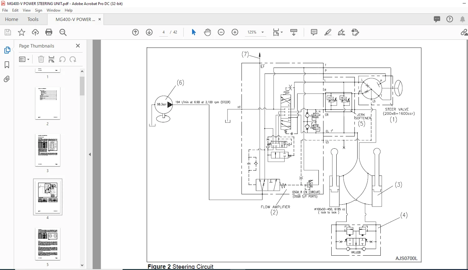
- The machine contains a fully hydraulic steering unit. See Figure 1. Rotating the steering wheel controls hydraulic flow through the steering valve. Figure 2, shows the hydraulic schematic for the steering system. The steering valve meters the volume of pump flow that is supplied to the steering cylinders
- The steering unit contains a gerotor. This allows the operator to steer the machine when the engine is not running or when the steering pump has failed. The gerotor functions as a manual hydraulic pump that is powered by the rotation of the steering wheel. Rotating the steering wheel will cause the gerotor to draw oil from the hydraulic tank and send this oil to the steering cylinders.
The shaft that is rotated by the steering wheel is attached to the spool (8, Figure 1) by the engagement of a spline. The spool is surrounded by a sleeve (3). The spool and sleeve are connected by the centering spring (2). At the steering wheel neutral position, the center pin does not contact the spool. A drive shaft (9) extends through the spool. The upper end of the drive shaft engages the center pin (4). The lower end of the drive shaft engages the spline in the gerotor (6).
Neutral Operation
With the steering wheel in the neutral position (wheels turned neither right nor left), the spool (2, Figure 3) and sleeve (1) are stationary at the position where the center pin (6) becomes centered in the spool space by the centering springs (3). Oil flow through the load sensing line (LS), port L, port R, and port T are bypassed to the tank line and the oil supply (P) is blocked by the directional spool in the steering unit (1, Figure 2). Even if an external force is applied to the steering cylinder, the steering unit is protected because the oil path is blocked by the directional spool
Right Turn
The spool (2, Figure 3) is engaged with the spline of the steering shaft. When the steering wheel is turned to the right, the spool turns. The sleeve (1) is connected to the spool (2) by centering springs (3). When spool turns, the sleeve turns. The sleeve turning angle is about 10° less than the spool turning angle. This allows the longitudinal slots in the spool to align with the ports in the sleeve. Oil from port P on the steering unit (1, Figure 2) travels through the control spool and is directed to port R which directs the oil to the steering cylinders (3, Figure 2). The amount of flow metered to port R is controlled by the amount of steering wheel rotation. Excess oil flow through port P that is not metered to port R, is directed by the spool to port T and is then directed through the il cooler and into the tank
Left Turn
The spool (2, Figure 3) is engaged with the spline of the steering shaft. When the steering wheel is connected to the spool (2) by centering springs (3). When the spool turns, the sleeve turns. The sleeve turning angle is about 10° less than the spool turning angle. This allows the longitudinal slots in the spool to align with the ports in the sleeve. When the steering wheel is turned to the left, oil from port P on the steering unit (1, Figure 2) is directed through the control spool in the steering unit, out port L and into the steering cylinders (3, Figure 2). The amount of oil flow metered to port L is controlled by the amount of steering wheel rotation. Excess oil flow through port P that is not metered to port L, is directed by the spool to port T and is then directed through the oil cooler and into the tank
GEROTOR OPERATION
If the engine or pump is not operating, the steering unit (1, Figure 2) works as a manual pump when the steering wheel is turned. The gerotor will work when the input torque to the steering wheel is less than 12 kg•m (87 ft. lbs.). If the necessary input torque is greater than this, the gerotor will not function. When the steering wheel is turned, the gerotor creates a vacuum that draws oil from port T. See Figure 2. The gerotor pumps this oil through the control spool and into the steering cylinders. Return oil flows back to the spool and is used to lubricate the steering unit (1, Figure 2). The return oil then flows back into the tank line and is recirculated back to the gerotor and the steering cylinders.
CUSHION VALVE OPERATION
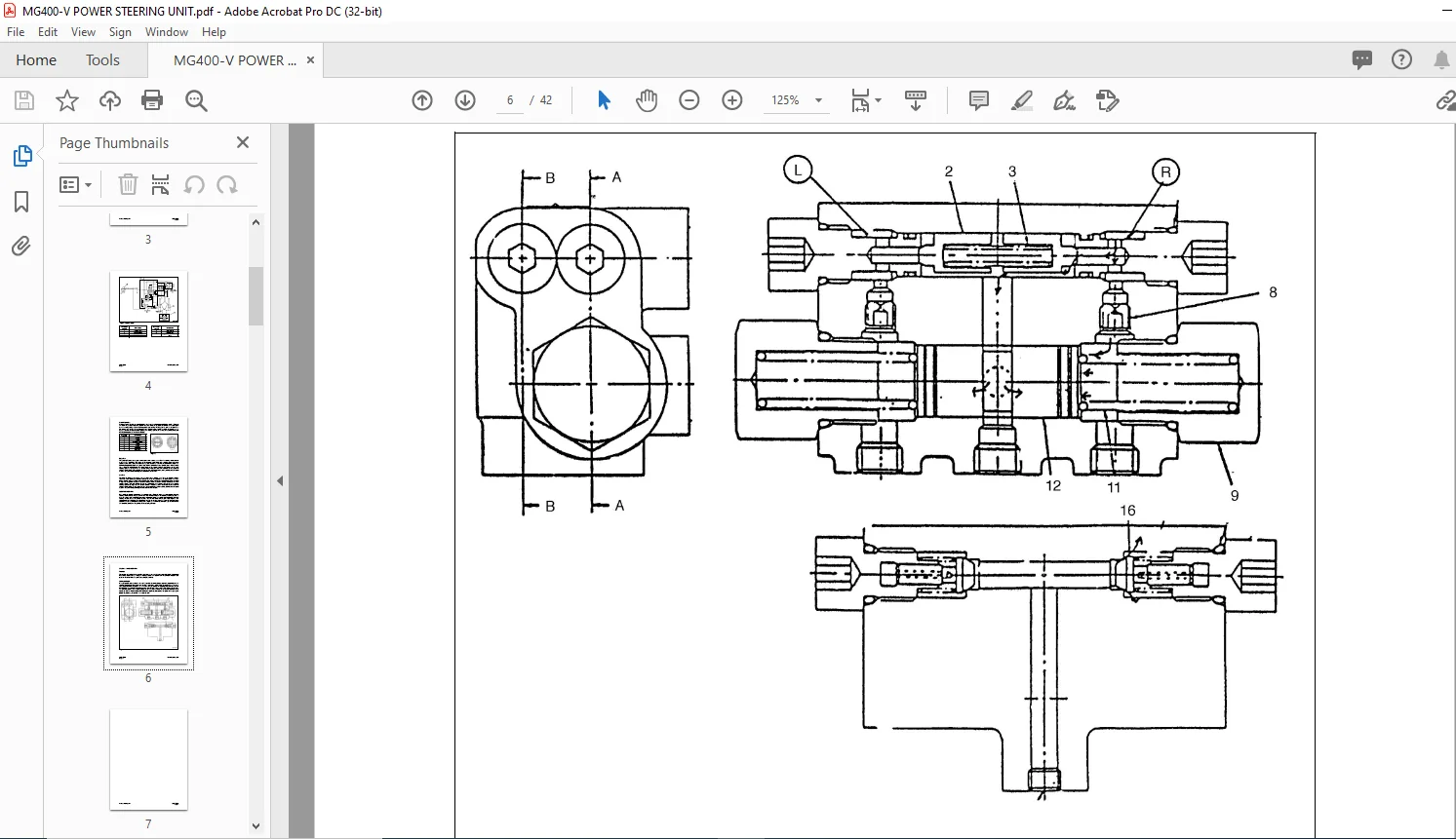
Function The cushion valve absorbs any excessive peak pressure that my be generated during initial movement of the steering wheel or during a change in steering direction. The cushion valve also prevents excessive high pressure and shock that can result from steering load inertia.
Working Principle
If a high pressure oil is fed back to the port R, it pushes the spring (3) and opens the poppet (2). And this operation directs the high pressure oil to the port L through the center hole in the spool (12) and the check valve poppet located in the port L part. At the same time, oil reaches the pressure room of the plug through the orifice (8). This operation closes the passage from the port R to the port L. This releases the pressure and prevents machine shock by intercepting oil. If a low pressure oil flows, the cushion operation is not necessary. It is due that the speed of the closing the spool (12) is faster than the speed of the opening the poppet (2), therefore, the cushion valve does not work
TABLE OF CONTENTS:
Daewoo Doosan MG 400-V 9POWER STEERING UNIT manual – PDF DOWNLOAD
General Description……………………………………………………………………………. 3
Power Steering System………………………………………………………………… 3
Gerotor Operation ……………………………………………………………………….. 5
Cushion Valve Operation………………………………………………………………. 6
Parts List ……………………………………………………………………………………. 8
Specifications……………………………………………………………………………… 9
Special Tools …………………………………………………………………………………… 10
Troubleshooting, Testing and Adjustment…………………………………………….. 12
Disassembly ……………………………………………………………………………………. 13
Cleaning and Inspection……………………………………………………………………. 17
Reassembly…………………………………………………………………………………….. 18
Installation ………………………………………………………………………………………. 29
Customer Support: [email protected]
IMAGES PREVIEW OF THE MANUAL:


PLEASE NOTE:
- This is the same manual used by the DEALERSHIPS to SERVICE your vehicle.
- The manual can be all yours – Once payment is complete, you will be taken to the download page from where you can download the manual. All in 2-5 minutes time!!
- Need any other service / repair / parts manual, please feel free to contact us at heydownloadss @gmail.com . We may surprise you with a nice offer
S.M