Daewoo Doosan MT36MT40B Trouble Shooting Manual – PDF DOWNLOAD
Original price was: $80.00.$28.95Current price is: $28.95.
Daewoo Doosan MT36MT40B Trouble Shooting Manual – PDF DOWNLOAD
Description
Daewoo Doosan MT36MT40B Trouble Shooting Manual – PDF DOWNLOAD
SAMPLE PAGE:
Daewoo Doosan MT36MT40B Trouble Shooting Manual – PDF DOWNLOAD
Injection Pump
Testing and reconditioning Reonditioning and testing should be carried out only at workshops having experienced personnel and the requiste equipment. In regard to repair instructions for the pump and governor, contact the pump manufactures and their organizations. Pumps and governors should be set in accoerdance with MOXY’s test tables. These list the settings and test equipment required for each type of pump
Injection timing
1. Remove the cover in the timing gear housing in front of the injection pump. The cover is fitted in the flywheel housing.
2. Set the prescribed injection pump timing on the flywheel. The injection timing is given on the plate on one of the rocker covers. If the setting is correct (at the right engine speed), the No. 1 cylinder should be at the end of its compression stroke, i.e. both inlet and exhaust valves should be closed (there should be a clearance between valve and rocker arm).
3. Insert the injection timing lock pin 8422 (alpha) through the hole in the driver and into the hole in the pump housing end plate. The holes are in line at about 9 o’clock
4. If the lock pin fits, the injection timing is set correctly. If the pin does not fit, adjust the pump drive as described in points 5-13
5. Undo the pump drive bolts. Leave the bolts in place
NOTE!
Point 6 must be carried out with care. The pump shaft can only be turned a degree or two either way.
If it in not possible to insert the lock pin through the elongated hole in the drive, it may be because the drive is incorrectly fitted.
6. Use a NV46 spanner to turn the pump shaft so that the lock pin can be pushed throught the hole in the driver and into the hole in the pump housing end plate. Leave the lock pin in place. Tighten the bolts in three stages as decribed below.
7. Tighten the two accessible pump drive bolts to 20 Nm (15 Ftlb)
8. Remove the lock pin.
NOTE!
If the lock pin is left in position when the bolts are tightened harder, the pump setting may be altered. The pump will then have to be reset on a test bench.
9. Titghten the two accessible botls to 80 Nm(59FtLb).
10. Carefully turn the engine until the third bolt becomes accessible and tighten it to 20 Nm (15 FtLb) and to 80Nm (59 FtLb) in two stages.
11. Turn the engine round one revolution and tighten the remaining bolts to 20 Nm (15 FtLb), 80 Nm (59 FtLb)and 110 Nm (81 FtLb) in three stages.
12. Turn the engine round revolution and tighten the remaining bolts.
13. Check that the lock pin can be pushed through the driver and into the pump end plate. Check on the flywheel that the timing is correct.
TABLE OF CONTENTS:
Daewoo Doosan MT36MT40B Trouble Shooting Manual – PDF DOWNLOAD
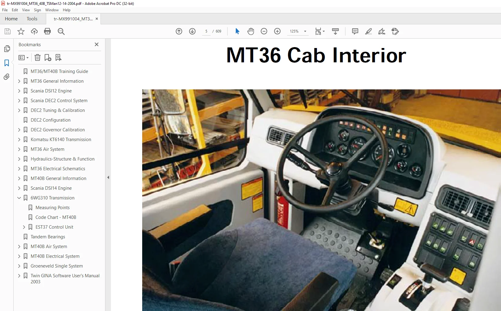
MT36/MT40B Training Guide..................................................  1
MT36 General Information...................................................  2
	New Body Design........................................................  3
	Tilting Cab............................................................  4
	Cab Interior...........................................................  5
	Controls...............................................................  6
	Switches...............................................................  7
	Engine.................................................................  8
		Electronic Control.................................................  9
	Transmission........................................................... 10
	Technical Data......................................................... 11
		Engine............................................................. 12
		Transmission....................................................... 12
		Hydraulic System................................................... 13
		Electrical System.................................................. 14
		Relays & Fuses..................................................... 15
		Meteric Conversion................................................. 16
		Performance Chart.................................................. 17
		Torque Limits...................................................... 18
		Serial Number Locations............................................ 19
Scania DSI12 Engine ....................................................... 20
	Cylinder Head.......................................................... 20
		Valve Adjustment................................................... 21
	Cylinder Block......................................................... 22
		Cylinder Block & Liners............................................ 23
	Crankshaft............................................................. 24
	Camshaft............................................................... 25
	Injection Pump.........................................................  0
		Removal............................................................ 26
		Fitting ........................................................... 28
		Timing Pg. 1....................................................... 30
		Timing Pg. 2....................................................... 31
Scania DEC2 Control System................................................. 32
	Control Unit........................................................... 33
	Basic Info............................................................. 34
	DEC2-MT36.............................................................. 35
	DEC2-MT40B............................................................. 36
	LED fuctions-Normal Operation.......................................... 37
	Sensors................................................................ 38
	Sensors (cont'd)....................................................... 39
	Control Rack Solenoid and Sensor....................................... 40
	Fuel Shut-off, Throttle Position Sensor................................ 41
	Electrical Warning..................................................... 42
	Engine Protection/Diagnostics.......................................... 43
	Fault Finding.......................................................... 44
		Procedure.......................................................... 45
		Critical Faults/Actions............................................ 46
		Shutdown/Actions................................................... 47
		DIP Switches....................................................... 48
		Obtaining Fault Codes.............................................. 49
		Dash Warning Light................................................. 50
		Test/Fault Switch.................................................. 51
		Chart Fault Codes.................................................. 52
		Computer Codes - Pg 1.............................................. 53
		Computer Codes - Pg 2.............................................. 54
		Connecting Table................................................... 55
			Actuator Solenoid-Fuel Pump.................................... 56
			Control Rack Sensor-Fuel Pump.................................. 57
			Fuel Shut Off Valve (EHAB)..................................... 58
			Engine Control-Accelerator Pedal............................... 59
			Location Engine Control........................................ 60
				Measuring Potentiometer.................................... 61
				Adjusting Potentiometer.................................... 62
			Boost Temperature Sensor....................................... 63
			Coolant Temperature Sensor..................................... 64
			Oil Pressure Sensor............................................ 65
				SPI 11/2000................................................ 66
				SPI 11/2000 (Page 2)....................................... 67
				SPI 11/2000 (Page3)........................................ 68
			Engine Speed Sensor............................................ 69
			Connector Identification & Pin No.s............................ 70
			No. 270 Connector (LH Side Cab)................................ 71
			Component Location on DSI12 Engine............................. 72
			Component Locations on DSI14................................... 73
			Component Locations in the Cab................................. 74
			Relay Locations................................................ 75
			Relay Indentification.......................................... 76
			Electrical Connections......................................... 77
DEC2 Tuning & Calibration.................................................. 78
	Laptop Start-up Procedure.............................................. 79
		Main Menu.......................................................... 80
		Engine Tuning...................................................... 81
		Explanation of Parameters.......................................... 81
		Explanation of Parameters - Page 2................................. 82
		Explanation of Function Keys....................................... 83
		Fault Log.......................................................... 84
			F-6 Codes...................................................... 85
			F-6 Codes - Page 2............................................. 86
DEC2 Configuration ........................................................ 87
DEC2 Governor Calibration.................................................. 88
	Settings............................................................... 88
	Procedures.............................................................  0
		Multimeter Hook Up................................................. 88
		Obtaining Readings................................................. 89
		Rack Travel........................................................ 90
		Adjusting Voltage.................................................. 90
			Trim Pot 2..................................................... 91
			Trim Pot 3..................................................... 92
	Failed Calibration..................................................... 93
		Possible Fault Messages............................................ 93
		Additional Errors.................................................. 94
	Calibration Passed..................................................... 94
		Saving the Calibration............................................. 94
	New Screens in 7.0/8.1................................................. 95
		Engine Maintenance Data............................................ 95
		PC Software Configuration.......................................... 96
			COM Port Selection............................................. 96
			OEM Information................................................ 97
Komatsu KT6140 Transmission................................................ 98
	Hydraulic Retarder Valve...............................................120
		Hydraulic Retarder Drain Valve.....................................121
		Retarder Operation - Retarder OFF..................................122
		Retarder Operation - Retarder ON...................................123
	Hydraulic Circuit Diagram.............................................. 99
	Torque Converter - External View.......................................100
	Torque Converter - Internal Parts......................................101
	Main Relief Valve......................................................102
		Operation of Main Relief...........................................103
	Torque Converter Main Relief...........................................104
	Torque Converter Lock Up - ECMV........................................105
	Converter Lock Up Operation............................................106
		Driving in Direct Drive............................................107
		Gear Shifting......................................................108
	Transmission Valves - ECMV.............................................109
		Breakdown of ECMV..................................................110
		Outline of ECMV....................................................111
		ECMV Actuation - Solenoid Energized................................112
		ECMV Actuation - Start of Fill.....................................113
		ECMV - Clutch Filling & Adjustment.................................114
	High - Low and Diff Lock Solenoid Valve................................115
		Operation of High - Low............................................116
		High - Low Not Changing............................................117
		Operation of Diff Lock ............................................118
		Diff Lock Won't Engage.............................................119
	Automatic Shift Control System.........................................124
		Transmission Shift Controller......................................125
		Controller Functions - Shift Pattern...............................126
		Braking and High Power Modes.......................................127
		Shift Lever Switch.................................................128
		Sensors and Switches...............................................129
	Transmission Testing and Adjusting.....................................130
		Standard Value Table - RPM.........................................131
		Standard Value Table - Pressure....................................132
		Standard Value Table - Electrical - Page 1.........................133
		Standard Value Table - Electrical - Page 2.........................134
		Standard Value Table - Electrical - Page 3.........................135
		Table of Tools.....................................................136
		Special Tool S.....................................................137
		Pressure Testing Ports.............................................138
		Testing Torque Converter Stall Speed...............................139
		Procedure for Moving Machine w/Failed Transmission.................140
		Adjusting Transmission and Engine Speed Sensors....................141
	Transmission Troubleshooting...........................................142
		Don'ts When Handling Connectors....................................142
		Handling Control Unit..............................................143
		Connector ID and Pin Numbers - X1 thru X3..........................144
		Connector ID - 10, 11A, 11B, 46 and96A.............................145
		Connector ID - 96B, 96C, 96E ......................................146
		Connector ID - 140.................................................147
		Transmission Controller Connections................................148
		Connecting Table - T/M Controller..................................149
		Self Diagnostic Display............................................150
		Error Code Finding.................................................151
		Judgement Table....................................................152
		Explanation of Trouble Shooting Charts.............................153
		Re-enacting Displayed Code.........................................154
		Precedure for re-enacting..........................................155
		Points to Remember in Testing......................................156
		Index of Troubleshooting Codes.....................................157
		Page 2 - Index Troubleshooting Codes...............................158
		Error Codes 0.1 to 0.6.............................................159
			Error Codes 0.7 to A-1.........................................161
			Error Codes 1.5 to 2.4.........................................163
			Error Codes 2.5 to 4._ (1-6,8).................................165
			Error Codes 4.1 to 5._ (1-6,8).................................167
			Error Codes 5.3 to 6.2.........................................169
			Error Codes 6.3 to 7.8.........................................171
			Error Codes 8.1 to 9.8.........................................173
			Error Codes F.A to F.F.........................................175
		Drawing Electrical Plug 140........................................177
	Judgement Table........................................................179
	Electrical Troubleshooting Charts......................................181
		A-1 Abnormality....................................................181
		A-2 Abnormality....................................................184
		A-3 Abnormality....................................................185
		A-4 Abnormality....................................................187
		A-6 Abnormality....................................................188
		A-7 Abnormality....................................................189
		A-8 Abnormality....................................................193
		A-9 Abnormality....................................................196
		A-10 Abnormality...................................................197
		Error Code 1.7.....................................................202
			Potentiometer Adjustment.......................................203
		A-12 Abnormality...................................................204
		A-13 Abnormality...................................................205
		A-14 Abnormality...................................................208
		A-15 Abnormality...................................................209
		A-16 Abnormality...................................................211
		A-17 Abnormality...................................................213
		A-18 Abnormality...................................................216
		A-19 Abnormality...................................................219
	Index Hydraulic Testing Charts.........................................222
		H-1 Machine Won't Start............................................225
		H-2 Machine Jerks..................................................227
		H-3 Lock Up Clutch Sticks..........................................227
		H-4 Excessive Shift Shock..........................................228
		H-5 No Up Shift....................................................228
		H-6 Lack of Power..................................................229
		H-7 Excessive Time Lag.............................................235
		H-8 High Converter Oil Temperature.................................237
		H-9 Low Converter Oil Pressure.....................................238
		H-10 High - Low Changeover.........................................239
		H-11 Diff Lock ON/OFF Failure......................................240
		H-12 Retarder ON/OFF Failure.......................................241
MT36 Air System............................................................242
	Air Supply System -410080..............................................243
	Air Supply System 410085-..............................................244
	Brake System 1.........................................................245
	Brake System 2.........................................................246
	Parking Brake System...................................................247
	Exhaust Brake System...................................................248
	Cab Central Air........................................................249
	Air Supply Driver's Seat...............................................250
	Tilting System.........................................................251
	Air Dryer..............................................................252
	Four-Way Protection Valve..............................................253
	Park Brake Valve.......................................................254
	Pneumatic Valves.......................................................255
	Tilt Servo Valve.......................................................256
	Diaphragm Cylinder.....................................................257
	Foot Brake Valve.......................................................258
Hydraulics-Structure & Function............................................260
	Schematic Diagram......................................................261
	Circuit Function.......................................................262
	Hydraulic Pumps........................................................263
	Tilting System.........................................................265
	Tilt Cylinder - Closed End.............................................267
	Tilt Cylinder - Oil Ports..............................................268
	Steering System........................................................269
	Steering Cylinder......................................................270
	Breakdown - Steering Cylinder..........................................271
	MT36 - Tip System w/Hydraulic, Pneumaticand Electric Switches..........272
	MT40B Tip System with Hydraulic, Pneumatic and Electrical Functions....278
	Explanation of Tip Circuit.............................................280
	Tilting Positions......................................................282
	Location of Float Valve & Switches.....................................286
	SPI 21/2000 - Protection For Float Valve...............................287
	Location 'S' Switch....................................................288
	Safety Relief Valve....................................................289
	Tilt Cylinder - Disassembled...........................................290
	'S' Port - Tilt Cylnder................................................291
	Tilt Valve - Exploded View.............................................292
	SPI 18/2000 - Plugs for Valve..........................................293
	Tilt Valve - Cut Away..................................................294
	Shock Valve & Relief Valve.............................................295
	Hydraulic Tank.........................................................296
	Hydraulic Pump (Double Pump)...........................................297
	Hydraulic System-Testing & Adjusting...................................298
		Measurement of Tip Pressures.......................................299
			Adjusting  Pressure-MT36.......................................300
				Access to Tilt Valve.......................................301
				Up Pressure................................................302
				Down Pressure..............................................304
				Two Position Relief Valve..................................305
			Adjusting Lift Pressure-MT40B..................................299
			Adjusting Lowering Pressure....................................307
			Adjustment of the 'S' Sensor...................................308
			Adjustment of 'S' Relief Valve.................................309
MT36 Electrical Schematics.................................................311
	Circuit 1 - Power Supply...............................................311
	Circuit 2 - Instrument Panel...........................................313
	Circuit 3 - Cab........................................................315
	Circuit 4 - Fuses and Relays...........................................317
	Circuit 5 - Engine Sensors.............................................319
	Circuit 6 - Transmission Sensors.......................................321
	Circuit 7 - Front Frame................................................323
	Circuit 8 - Rear Frame.................................................325
	Circuit 9 - Switchboards...............................................327
	Lock-Up Circuit........................................................330
	Exhaust Brake Circuit..................................................331
	Retarder Circuit.......................................................332
	Inter Axle Lock Circuit................................................333
	High/Low Range Circuit.................................................334
	AC Circuit.............................................................335
	Auto Lube Circuit......................................................336
MT40B General Information..................................................337
	MT40B .................................................................337
	Technical Data.........................................................338
		Measurements.......................................................338
		Engine Specs.......................................................339
		Hydraulic System...................................................340
		Electrical System..................................................341
		Performance Chart..................................................344
		Exhaust Brake & Retarder Capacity..................................345
		Torque Limits for Bolts............................................346
		Serial Number Plates...............................................347
	MT40B Weight&Volume....................................................348
	MT40B Engine...........................................................349
	MT40B Transmission.....................................................350
	MT40B Body.............................................................351
	MT40B Cab..............................................................352
Scania DSI14 Engine........................................................355
	Individual Cylinder Heads..............................................355
	Engine Block...........................................................356
	Crankshaft.............................................................357
	Piston.................................................................358
	Timing Gears/Camshaft..................................................359
	Oil Pump...............................................................360
	Intake Manifold........................................................361
6WG310 Transmission........................................................363
	Measuring Points.......................................................363
	Code Chart - MT40B.....................................................364
	EST37 Control Unit.....................................................  0
		Digital Display....................................................365
		Explanation of Codes...............................................366
		Display During AEB.................................................367
		Operating Modes....................................................368
		Table of Fault Codes...............................................  0
			Fault Codes 11-26..............................................369
			Fault Codes 27-35..............................................370
			Fault Codes 36-65..............................................371
			Fault Codes 66-76..............................................372
			Fault Codes 77-84..............................................373
			Fault Codes 85-92..............................................374
			Fault Codes 93-6F..............................................375
			Fault Codes 9A-A4..............................................376
			Fault Codes A5-B5..............................................377
			Fault Codes B6-BF..............................................378
			Fault Codes D3-F6..............................................379
		Measuring Resistance of Sensors....................................380
		Location Senders on Transmission...................................381
		Electrical Schematic...............................................383
		VTS-3 Gear Selector-Testing........................................384
Tandem Bearings............................................................389
MT40B Air System...........................................................393
	Air Supply System......................................................394
	Moisture Drain System..................................................395
	Brake Circuit 1........................................................396
	Rear Brake Circuit, Front Vehicle......................................397
	Rear Brake Circuit.....................................................398
	Parking Brake System, Front Vehicle....................................399
	Rear Parking Brake System..............................................400
	Tilting System.........................................................401
	Air Pressure System - Front............................................402
	Hydraulic Retarder.....................................................403
	Four-Way Protection Valve..............................................404
	Diaphragm, Main Brakes.................................................405
	Parking Brake Servo Valve..............................................406
	Air Governor...........................................................407
	Pneumatic Valves.......................................................408
	Relay Valve............................................................409
	Air Dryer..............................................................410
	Air Cylinder - Park Brake..............................................411
	Tilt Servo Valve.......................................................412
	Foot Brake Valve.......................................................413
	Retarder Valves........................................................414
MT40B Electrical System....................................................  0
	MT40B Index - Electrical System........................................415
	Welding Warning........................................................416
	How Index Works........................................................417
	Description of Electrical Symbols......................................418
	Specifications - Engine Components.....................................419
	Specifications - DEC2 Components.......................................420
	Specifications (cont'd)................................................421
	Specifications - Transmission..........................................422
	Specifications - General...............................................423
	Specifications - General...............................................424
	Cross Reference List - 1...............................................425
	Cross Reference List - 2...............................................426
	Cross Reference List - 3...............................................427
	Cross Reference List - 4...............................................428
	Cross Reference List - 5...............................................429
	Cross Reference List - 6...............................................430
	Cross Reference List -7................................................431
	Map 01 - Starting and Charging.........................................432
	Map 02 - Front Frame...................................................433
	Map 03 - Rear Frame....................................................434
	Map 04 - Engine........................................................435
	Map 05 - DEC2..........................................................436
	Map 06 - Transmission..................................................437
	Map 07 - Cab Outside, Front............................................438
	Map 07 - Cab Outside, Rear.............................................439
	Map 10 - Instrument Panel..............................................440
	Map 12 - Cab Inside Lower Left Side....................................441
	Map 12 - Cab Inside Lower Right Side...................................442
	Map 13 - Cab Inside....................................................443
	Map 14 - Fuse Box and Relays...........................................444
	Map 15 - Fuse and Relay Indentification................................445
	Circuit 01 - Compartment and Cab Light.................................446
	Circuit 02 - Brake Light...............................................447
	Circuit 03 - Power Supply, Starting....................................448
	Circuit 04 - Extra High Beam...........................................449
	Circuit 05 - Heated Seat, Mirrors, & Air Dryer.........................450
	Circuit 06 - Fan and A/C...............................................451
	Circuit 07 - Flame Start...............................................452
	Circuit 08 - Working Light.............................................453
	Circuit 09 - Reverse and Work Light....................................454
	Circuit 10 - Instrument Light..........................................455
	Circuit 11 - Lighter...................................................456
	Circuit 12 - Rotating Beacon...........................................457
	Circuit 13 - Radio.....................................................458
	Circuit 14 - Wiper, Washer and Horn....................................459
	Circuit 18 - Engine Wiring Diagram.....................................460
	Circuit 19 - Transmission Wiring Diagram...............................461
		VTS-3 Gear Selector-Testing........................................462
	Circuit 20 - Brake Warning.............................................464
	Circuit 21 - Headlight.................................................465
	Circuit 22 - Tilting System............................................466
	Circuit 23 - Tachometer, Fuel Gauge, Voltmeter.........................467
	Circuit 24 - Direction and Hazard Light................................468
	Electric Circuit Auto Lube.............................................469
	Location of Senders - Instrument Panel ................................470
	Contact Arrangements...................................................471
Groeneveld Single System...................................................472
	Outline of System......................................................473
	Pneumatic Pump.........................................................474
	Filling Reservoir......................................................475
	Timer..................................................................476
	Solenoid Valve.........................................................477
	Pressure Switch........................................................478
	Distribution Blocks....................................................479
	Metering Units.........................................................480
	Test 1.................................................................481
	Test 2.................................................................482
	Test 3.................................................................483
	Timer Display Unit.....................................................484
		Hook Up TDU........................................................485
		Read Timer.........................................................486
Twin GINA Software User's Manual 2003......................................492
	Table of contents......................................................494
	Introduction...........................................................498
		1.1 Introduction...................................................499
		1.2 Groeneveld Transport Efficiency B.V............................499
		1.3 Twin GINA Programming Software.................................500
	Installation...........................................................502
		2.1 System requirements............................................503
		2.2 Installing the software........................................503
		2.3 Changing the serial port (COM-port) setting....................505
		2.4 Removing the software..........................................506
	Starting the program...................................................508
		3.1 Starting the program...........................................509
		3.2 Validating the program.........................................509
		3.3 Making a connection............................................510
		3.4 Working offline................................................511
		3.5 Closing the program............................................511
	Functions..............................................................512
		4.1 Introduction...................................................513
		4.2 File menu......................................................513
		4.3 Reports menu...................................................514
		4.4 Twin menu......................................................515
		4.5 Language.......................................................516
		4.6 About..........................................................516
	Parameters.............................................................518
		5.1 Parameter settings and read-outs...............................519
		5.2 The Main (F9) tab..............................................519
		5.3 The Parameters (F10) tab.......................................522
		5.4 The Errors (F11) tab...........................................526
		5.5 The Diagnosis (F12) tab........................................528
	Reports................................................................534
		6.1 Introduction...................................................535
		6.2 Entering data of pump unit currently connected.................535
		6.3 Viewing a report...............................................537
		6.4 Printing a report..............................................538
		6.5 Editing a report...............................................538
		6.6 Importing a report.............................................539
		6.7 Exporting a report.............................................539
	Shop Manual............................................................542
		Table of Contents..................................................543
		Introduction.......................................................548
		Using Manual.......................................................549
		Safety Precautions.................................................550
		Evironmental Considerations........................................551
		Composition........................................................552
		Operating Principle................................................553
		Operation..........................................................556
		The Twin Pump Unit.................................................557
			5/2 Solenoid Valve.............................................559
		Dosers and Doser Blocks............................................560
			Principle of Operation.........................................561
			Grease Pressure Switch.........................................562
			Signal Light...................................................563
			Test Button....................................................564
			Filing Grease Reservoir........................................566
		Maintenance........................................................568
			Fault Finding Charts...........................................570
			Grease Reservoir...............................................575
			Filler Coupling & Filter.......................................580
			Test Push Button...............................................586
			Control Unit...................................................587
			Minimum-Level Switch...........................................589
			Solenoid Valve.................................................590
			Pump Assembly..................................................595
			Electric Pump Motor............................................599
			Testing the Pump...............................................603
			Installation...................................................605
				Electrical Connections.....................................606
			Technical Data.................................................607
DAEWOO DOOSAN MT36MT40B TROUBLE SHOOTING MANUAL – PDF DOWNLOAD:
IMAGES PREVIEW OF THE MANUAL:
PLEASE NOTE:
- This is not a physical manual but a digital manual – meaning no physical copy will be couriered to you. The manual can be yours in the next 2 mins as once you make the payment, you will be directed to the download page IMMEDIATELY.
- This is the same manual used by the dealers inorder to diagnose your vehicle of its faults.
- Require some other service manual or have any queries: please WRITE to us at [email protected]
S.M