Daewoo Doosan Solar 140/160W-V Shop Manual 023-00065E – PDF DOWNLOAD
$34.95
Daewoo Doosan Solar 140/160W-V Shop Manual 023-00065E – PDF DOWNLOAD
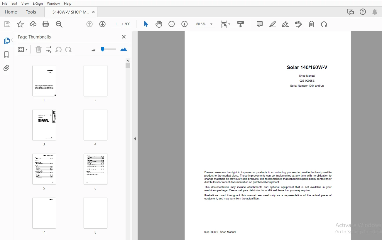
Shop Manual
023-00065E
Serial Number 1001 and Up
Description
Daewoo Doosan Solar 140/160W-V Shop Manual 023-00065E – PDF DOWNLOAD
FILE DETAILS:
Daewoo Doosan Solar 140/160W-V Shop Manual 023-00065E – PDF DOWNLOAD
Language :English
Pages :900
Downloadable : Yes
File Type : PDF
IMAGES PREVIEW OF THE MANUAL:
DESCRIPTION:
Daewoo Doosan Solar 140/160W-V Shop Manual 023-00065E – PDF DOWNLOAD
Shop Manual
023-00065E
Serial Number 1001 and Up
GENERAL SAFETY ESSENTIALS
ACCESSORY APPLICATIONS
The excavator has been primarily designed for moving earth with a bucket. For use as a grapple or for
other object handling, contact Daewoo for proper installation and application. Lifting-work applications
(unless restricted or prohibited by local regulations) are permitted in approved lift configuration, to rated
capacity only, with no side-loading. DO NOT use the machine for activities for which it was not intended.
DO NOT use the bucket for lifting work, unless lift slings are used in the approved configuration.
Use of an accessory hydraulic hammer (breaker), work in rough terrain, demolition applications or other
hazardous operation may require installation of additional protective structures to safeguard the operator.
LIFTING CAPACITY RATING CONFIGURATION
Lifting capacity ratings that are printed at the end of this safety section are based on the machine being
level, on a firm supporting surface, with hooks and slings attached in approved configuration. Loads must
be balanced and supported evenly. Use taglines to keep the load steady if wind conditions and large
surface area are a problem. Work crew hand signals, individual tasks and safe procedures should all be
universally understood before the lift is made.
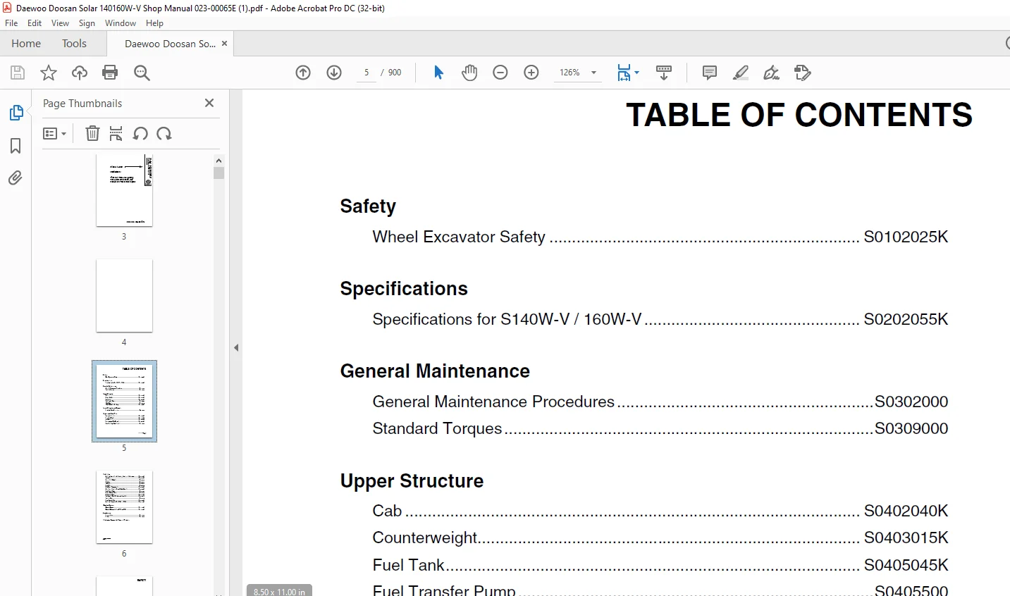
TABLE OF CONTENTS:
Daewoo Doosan Solar 140/160W-V Shop Manual 023-00065E – PDF DOWNLOAD
Shop Manual
023-00065E
Serial Number 1001 and Up
Safety 7
Wheel Excavator Safety S0102025K 9
To the Operator of a Daewoo Excavator 11
Learn the Signal Words Used with the Safety Alert Symbol 13
General Safety Essentials 14
Accessory Applications 14
Lifting Capacity Rating Configuration 14
Location of Safety Labels 14
Summary of Safety Precautions for Lifting in Digging Mode 15
Unauthorized Modifications 16
General Hazard Information 16
Safety Rules 16
Safety Features 16
Inside Operator’s Compartment 17
Clothing and Personal Protective Items 18
Breathing Masks, Ear Protection May be Required 18
Mounting and Dismounting 19
Fuel, Oil and Hydraulic Fluid Fire Hazards 20
Precautions When Handling Fluids at High Temperature 20
Asbestos Dust Hazard Prevention 21
Injury from Work Equipment 21
Fire Extinguisher and First Aid Kit 22
Protection from Falling or Flying Objects 22
Attachment Precautions 23
Accumulator 23
Indoor Ventilation 24
Emergency Exit 24
Before Starting Engine 25
Work Site Precautions 25
Checks Before Starting Engine 26
Engine Starting 27
Before Operating Machine 27
Machine Operation 28
When Swinging or Changing Direction of Travel 28
Travel Precautions 28
Traveling on Slopes 29
Prohibited Operations 30
Precautions for Operation 30
Avoid High-voltage Cables 31
Operate Carefully on Snow, Ice and in Very Cold Temperatures 31
Operations on Slopes 32
Parking Machine 32
Never Let Anyone Ride on Attachment 32
Maintenance 33
Warning Tag 33
Clean Before Inspection or Maintenance 33
Proper Tools 34
Use of Lighting 34
Fire Prevention and Explosion Prevention 34
Burn Prevention 35
Welding Repairs 36
Warning for Counterweight and Front Attachment Removal 36
Precautions for Removal, Installation, and Storage of Attachments 37
Precautions when Working on Machine 37
Lock Inspection Covers 37
Crushing Prevention and Cutting Prevention 37
Supports and Blocking for Work Equipment 38
Action When Abnormally Is Found During Inspection 39
Precautions with High Pressure Line, Tubes and Hoses 39
Waste Materials 40
Battery 41
Battery Hazard Prevention 41
Boost Starting or Charging Engine Batteries 42
Towing 43
Precautions When Towing 43
Shipping and Transportation 44
Obey State and Local Over-the-Road Regulations 44
Lifting With Sling 44
Specifications 45
Specifications for S140W-V / 160W-V S0202055K 47
General Description 50
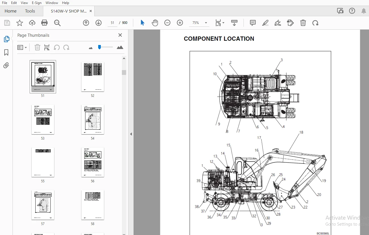
Component Location 51
SOLAR 140W-V 53
General Dimensions 53
Working Range 54
SOLAR 160W-V 56
General Dimensions 56
Working Range 57
Front Linkage Pin Size 59
Hydraulic Cylinders 60
Engine Specifications 61
Engine Performance Curves (Per DIN 6270 Standard) 63
Approximate Weight of Workload Materials 64
General Specifications 67
Hydraulic System Component Specifications 69
System Component Specifications 70
Drive System 70
Swing Mechanism 70
Brake System 71
Steering System 72
Chocking System 72
Performance Tests and Standards 73
Standards 73
Tests 74
Test Conditions 74
Travel Speed Tests 75
Swing Speed Test 76
Swing Speed Test 76
Swing Deceleration Force Test 76
Cylinder Performance Tests 77
Boom Cylinders Test 77
Arm Cylinder Test 77
Bucket Cylinder Test 77
Hydraulic Cylinder Natural Drop Test 77
General Maintenance 79
General Maintenance Procedures S0302000 81
Welding Precautions and Guidelines 83
Hydraulic System – General Precautions 84
Maintenance Service and Repair Procedure 85
General Precautions 85
Hydraulic System Cleanliness and Oil Leaks 86
Maintenance Precautions for Hydraulic System Service 86
Oil Leakage Precautions 86
Cleaning and Inspection 87
General Guidelines 87
Bearing inspection 88
Standard Torques S0309000 95
Torque Values for Standard Metric Fasteners 97
Torque Values for Standard US Fasteners 98
Type 8 Phosphate Coated Hardware100
Torque Values for Hose Clamps101
Torque Values for Split Flanges102
Torque Wrench Extension Tools103
Torque Multiplication103
Other Uses for Torque Wrench Extension Tools104
Tightening Torque Specifications (Metric)104
Upper Structure107
Cab S0402040K109
Removal111
Installation114
Counterweight S0403015K117
General119
Removal121
Installation123
Fuel Tank S0405045K125
General Description127
Parts List128
Specifications129
Removal130
Installation134
Start-up Procedures136
Fuel Transfer Pump S0405500137
General Description139
Theory of Operation139
Troubleshooting140
Replacement of Rotor and Vane140
Replacement of Rear Cover141
Replacement of Armature142
Swing Bearing S0407010143
Swing Bearing Maintenance145
Operating Recommendation145
Measuring Swing Bearing Axial Play145
Measuring Bearing Lateral Play145
Swing Bearing Basic Operation146
Rebuilding Swing Bearing146
Swing Reduction Gearbox S0408025K149
General Description151
Theory of Operation151
Parts List152
Special Tools and Materials154
Special Tools154
Troubleshooting, Testing and Adjustment155
Removal156
Disassembly158
Reassembly160
Installation162
Lower Structure and Chassis163
Ram Lock Valve Operation S0503000165
Theory of Operation167
Engine and Drive Train169
Front Axle (Dana) S0602055K171
Introduction174
Introductory Remarks174
Maintenance and Lubricant175
Definition of Viewpoints175
Data Plate175
Maintenance Points176
Maintenance Intervals177
Adjustment and Checks177
Tightening Torques178
Screw-locking, Sealing and Lubricating Materials179
Notes on Safety Precautions181
Checking Wear and Replacing Brake Disks182
Disassembly of Brake Units182
Assembly of Brake Units186
Steering Case189
Removal and Disassembly189
Assembly and Installation193
U-Joint195
Notes on Safety Precautions195
Removal and Disassembly196
Assembly and Installation200
Planetary Reduction203
Disassembly203
Assembly209
Steering Cylinder215
Removal215
Installation218
Disassembly222
Assembly225
Differential Unit228
Removal and Disassembly228
Assembly, Adjusting and Installation234
Bevel Pinion241
Removal241
Adjusting and Installation245
Special Tools253
Troubleshooting259
Rear Axle (Dana) S0602056K263
Introduction265
Introductory Remarks265
Maintenance and Lubricant266
Definition of Viewpoints266
Data Plate266
Maintenance Points267
Maintenance Intervals268
Adjustment and Checks268
Tightening Torques270
Screw-locking, Sealing and Lubricating Materials271
Notes on Safety Precautions273
Checking Wear and Replacing Brake Disks274
Disassembly of Brake Units274
Assembly of Brake Units277
Planetary Reduction and Axle Shaft280
Notes on Safety Precautions280
Disassembly281
Assembly286
Bevel Pinion292
Removal292
Adjusting and Installation297
Special Tools306
Troubleshooting312
Air-Conditioner S0605060K315
General Description317
Refrigerant Circulation319
Control Panel321
Control Specifications322
Temperature Level Control and Display323
Air Discharge According to Path Selection324
Air-conditioning System Circuit Diagram326
Troubleshooting328
Weight of R134a Gas Used In Machines331
Refrigerant System Repairs333
Refrigerant Safe Handling Procedures333
Repair and Replacement Procedure334
Refrigerant Recovery336
Vacuuming Refrigerant System336
Leakage Check337
Refrigerant Charging338
Inspecting System For Leakage340
Transmission (ZF 2HL-100) S0607055K341
Specifications344
Transmission Operation345
Transmission Disassembly346
Detaching Drive (Input) Housing346
Disassembling Input Shaft Assembly347
Disassembling Planetary Drive354
Disassembling Clutch and Spur Gear355
Disassembling Shift Lock360
Final Drive, Drive Shaft and Differential Disassembly362
Transmission Reassembly367
Shimming Drive Pinion367
Reassembling Drive Pinion368
Adjusting Rolling Resistance of Drive Pinion Bearing372
Installing Differential374
Adjusting Backlash and Bearing Preload378
Installing Helical Gear and Clutch379
Installing Planetary Carrier383
Adjusting Shift Lever384
Preassembling and Installing Clutch385
Checking Clutch392
Installing Brake393
Installing Drive Casing397
Drive Pinion / Crown Wheel Contact Pattern401
Correct Pattern401
Increase Pinion Distance401
Decrease Pinion Distance402
Transmission Governor403
Parts List403
Disassembly of Governor405
Reassembly of Governor406
Drive Coupling (Main Pump) S0609000407
Drive Coupling409
Special Tools410
Kawasaki / Tong Myung Pump Tool410
Uchida Pump Tool413
Drive Coupling Installation414
Installation Procedure419
Hydraulics421
Hydraulic System Troubleshooting, Testing and Adjustment S0702065K423
Hydraulic System – General Notes426
Hydraulic Schematic428
General Notes428
Operation of Working Components429
Boom Operating Circuit429
Boom Up Circuit429
Boom Down Circuit429
Arm Operating Circuit430
Arm Crowd Circuit430
Arm Dump Circuit431
Bucket Operating Circuit431
Bucket Crowd Circuit431
Bucket Dump Circuit432
Swing Operating Circuit432
Right Swing Operating Circuit432
Left Swing Operating Circuit433
Swing Relief Valve and Make-up Valve433
Procedural Troubleshooting Baseline Recommendations434
Initial Checks and Tests to Establish Operating Condition of the Excavator434
Pilot Pressure435
Adjustment and Testing435
Power Mode Valve436
Current Signal and Hydraulic Pressure Adjustments436
Swing Priority Valve437
Control Valve Pressure and Current Adjustments437
Pressure Up Valve438
Checks and Adjustments438
Pump Input Power Control440
Pump Regulator Adjustment440
Flow Meter and Flow Meter Kit Installation and Testing444
Swing System Troubleshooting446
Precautions/Initial Checks446
Swing Relief Valve Checking and Adjustment446
Troubleshooting – Swing Gearbox448
Troubleshooting – Hydraulic Problems450
Troubleshooting – Control Valve452
Troubleshooting – Travel Pedal Valve454
Troubleshooting – Joystick Control Valve455
Accumulator S0703010K457
General Description459
Specifications460
Center Joint (Swivel) S0704070463
General Description465
Parts List466
Troubleshooting, Testing and Adjustment468
Inspection468
Testing468
Disassembly469
Reassembly470
Cylinders S0705000471
General Description473
Theory of Operation473
Parts List474
Special Tools and Materials476
Piston Nut476
Piston Jig480
Steel bush Jig484
Dust Wiper Jig488
Slipper Seal Jig494
Slipper Seal Straightening Jig498
Disassembly501
Assembly507
Swing Motor S0707260511
General Description513
Theory of Operation513
Swing Motor Anti-cavitation Make-up Valve514
Relief Valve515
Swing Brake Operation516
Parts List (Solar 140W-V, 160W-V)518
Parts List (Solar 170LC-V, 170W-V, 450LC-V, 470LC-V)520
Specifications522
Special Tools (Solar 140W-V, 160W-V)523
Special Tools (Solar 170LC-V, 170W-V)524
Special Tools (Solar 450LC-V, 470LC-V)525
Disassembly526
Cleaning and Inspection (Wear Limits and Tolerances)533
Reassembly535
Travel Motor S0707350543
General Description546
Theory of Operation546
Parts List548
Specifications549
Travel Motor General Disassembly and Reassembly Instructions550
Recommended Tools550
Precautions for Disassembly and Assembly550
Disassembly of Travel Motor551
Appearance of Motor551
Removal of counterbalance Valve551
Removal of Outer Piping552
Removal of Stroke Limiter553
Removal of Oil Seal554
Removal of Control Unit554
Removal of Control Valve556
Disassemble Control Valve558
Disassemble Stroke Limiter559
Reassemble Stroke Limiter560
Reassemble Control Valve560
Installation of Control Valve561
Reassembly of Travel Motor564
Assembly of Control Unit564
Installation of Oil Seal566
Installation of Stroke Limiter567
Installation of Outer Piping567
Installation of Counterbalance Valve568
Main Pump (Tongmyung) S0708306K569
Swash Plate Type K5V Series Axial Piston Pump572
Type Designation572
Specifications573
Construction and Function574
Cautions for Operation576
Troubleshooting579
Construction of Tandem Type Duplex Pump582
Tools584
Axial Piston Pump Disassembling586
Axial Piston Pump Reassembling590
Axial Pump Maintenance Criteria593
Tightening Torques594
Regulator for T5V Series of Tongmyung Swash Plate Type Axial Piston Pump595
Type Description595
Construction of Regulator596
Functional Explanations598
Adjustment of Maximum and Minimum Flows603
Fault Finding and Remedies on Regulator604
Preparation for Disassembly606
Tools606
Regulator Disassembly607
Regulator Reassembly610
Tightening Torque613
Gear Pump (Steering Pump & Brake Pump) S0708435K615
General Description617
Theory of Operation617
Parts List617
Specifications618
Brake Supply Valve S0709220619
Parts List622
Specifications623
Counterbalance Valve S0709300625
General Description627
While Operating to Run Forward627
While Operating to Stop627
While Operating to Back627
Adjustment of Relief Valve628
Troubleshooting629
Counterbalance Valve630
Recommended Tools630
Disassembly630
Order of Disassembly and Torque Values631
Reassembly632
Main Control Valve S0709416K637
Control Valve Operation641
Arm Priority Circuitry642
Bucket (Junction) Circuitry644
Straight Traveling Circuit646
Plunger Replacement650
Main Relief Valve651
Overload Relief Valve652
Arm Load Holding Valve654
Boom Load Holding Valve657
Arm Regeneration659
Foot Relief Valve661
Parts List662
Specifications671
Control Valve Drawing and Hydraulic Circuit672
Disassembly and Reassembly677
General Disassembly677
General Reassembly677
Main Plunger Element678
Main Relief Valve681
Main Relief Valve Adjustment682
Overload Relief Valve684
Overload Relief Valve (BM UP)686
Arm Load Holding Valve688
Boom Load Holding Valve691
Arm Regeneration Valve693
Foot Relief Valve694
Center Bypass Valve (CB Valve)695
Arm Parallel Switch Valve696
Boom Unity Check Valve698
Straight Travel Selector Valve699
Check Valve – Locations700
Check Valve701
Pilot Control Valve (Work Lever / Joystick) S0709451K705
General Description707
Theory of Operation707
Parts List708
Specifications709
Removal710
Disassembly713
Cleaning and Inspection (Wear Limits and Tolerances)717
Reassembly718
Installation723
Start-up Procedures724
Steering Valve S0709710725
General Description727
Theory of Operation728
Parts List730
Specifications731
Special Tools and Materials732
Special Tools732
Disassembly734
Reassembly743
Dozer Control Valve S0709905K757
Parts List759
Specifications760
Hydraulic Schematic (S140W-V / 160W-V) S0792145K761
General Description763
Solar 140W-V / 160W-V764
Electrical System767
Electrical System S0802125K769
Troubleshooting – Electrical System773
Overview774
Electric Supply System775
Engine Starting Circuit776
Operation During Start Process776
Operation After Start Process777
Engine Preheating System778
Engine Stop System779
Charging System782
Monitoring System784
Instrument Panel786
Monitoring System Schematic788
Operation790
Instruments790
Warning and Indicator Lights792
Control Unit794
Operation Schematic794
Operation Specification795
Console Warning Light796
Initial Operation798
Mode Select Switch799
Graphic Information Area Display800
Overview800
Main Menus for the Graphic Display Area801
Menu Selection Buttons801
Main Menu802
Language setting802
Time Setting802
Filter/Oil information803
Special Menu804
Entering/Accessing and Exiting/Escaping Menus804
Special Menu Selections805
Electronic Hydraulic Control System (e-EPOS)818
Power Mode Control820
Operation821
Throttle Position Sensor824
Power Mode Control – Circuit Diagram826
Work Mode Control828
Operation829
Work Mode Control – Circuit Diagram830
Engine Control System832
Engine Control Motor833
Engine Control Dial834
Engine Control Circuit Diagram836
Automatic Deceleration Control (Auto Idle Control)837
Automatic Deceleration Control Circuit838
Operation839
Engine Overheat Protection System840
Power Boost Mode841
Operation841
Power Boost Control – Circuit Diagram842
Cruise Control844
Cruise Control Circuit846
Adjusting Method of Engine Control Unit848
Adjusting Method of Engine Control System848
Adjusting Method of Engine RPM850
Adjustment of TPS (Throttle Position Sensor)855
Self-diagnostic Function860
e-EPOS Controller860
Engine Throttle Controller864
Wiper System866
Wiper Circuit866
Wiper Operation866
Window Washer Operation867
Overload Warning Device868
Overload Warning Device Circuit Diagram868
Electrical Schematic (S140W-V / 160W-V) S0892075K869
General Description871
Solar 140W-V / 160W-V872
Attachments875
Boom and Arm S0902060877
Front Attachment Pin Specifications879
Front Attachment – Removal and Installation880
Arm Removal Procedure880
Boom Removal Procedure882
Front Attachment – Installation883
Arm Installation Procedure883
Boom Installation Procedure883
Start-up Procedures884
Bucket S0904000885
Bucket Tooth Inspection and Replacement887
Type 1887
Type 2888
Type 3889
Bucket O-ring Replacement891
Type 1891
Type 2892
Bucket Shimming Procedures894
New Bucket Installation894
Type 1894
Type 2895
Bucket Attachment, Removal and Reversal896
Detaching the Bucket896
Attaching The bucket896
Reversing the Bucket897
Publication Request for Proposed Revision899
S.M 14/2/2025