Daewoo Doosan Solar 400LC-III Shop Manual 2023-7096E-1 – PDF DOWNLOAD
Original price was: $56.95.$31.95Current price is: $31.95.
Daewoo Doosan Solar 400LC-III Shop Manual 2023-7096E-1 – PDF DOWNLOAD
Solar 400LC-III
Shop Manual
2023-7096E-1
Serial Number 0080 and Up
April 1996
Description
Daewoo Doosan Solar 400LC-III Shop Manual 2023-7096E-1 – PDF DOWNLOAD
DESCRIPTION:
Daewoo Doosan Solar 400LC-III Shop Manual 2023-7096E-1 – PDF DOWNLOAD
Solar 400LC-III
Shop Manual
2023-7096E-1
Serial Number 0080 and Up
April 1996
Accessory Applications:
- The excavator has been primarily designed for moving earth with a bucket. For use as a grapple or for other object handling, contact Daewoo.
- Lifting work applications are permitted in approved lift configuration, to rated capacity only, with no sideloading.
- DO NOT use the machine for activities for which it was not intended.
- DO NOT use the bucket for lifting work, unless lift slings are used in the approved configuration.
Lifting:
- Lifting capacity ratings that are printed at the end of this safety section are based on the machine being level, on a firm supporting surface, with hooks and slings attached in approved configuration.
- Loads must be balanced and supported evenly.
- Use taglines to keep the load steady if wind conditions and a large surface area are a problem.
- Work crew hand signals, individual tasks, and safe procedures, should all be universally understood before the lift is made.
IMPORTANT:
- Before using the excavator to make lifts, check with all appropriate levels of government to be certain that lifting is legal.
- In some areas it may be a legal requirement to use a crane for lifting objects.
- In some areas it may be illegal to use for lifting, a machine designed to also perform digging, loading, and grading operations.
- Always follow all instructions, guidelines, and restrictions for Safe Lifting in both the Operation and Maintenance Manual and the Shop Manual.
Locations of Safety Labels:
- Always keep these labels clean.
- If they are lost or damaged, replace them with a new label.
- There are other labels in addition to the safety labels that follow, so handle them in the same way.
- Safety labels may be available in languages other than English.
- To find out what labels are available, contact your Daewoo distributor.
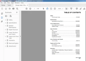
TABLE OF CONTENTS:
Daewoo Doosan Solar 400LC-III Shop Manual 2023-7096E-1 – PDF DOWNLOAD
SAFETY
To the Operator of a Daewoo Excavator . . . . . . . . . . . . . . . . . . . . . . . . . . . . . . . . . . . . . . . . . . . . . 1-1
Basic Excavator Operating Safety . . . . . . . . . . . . . . . . . . . . . . . . . . . . . . . . . . . . . . . . . . . . . . . . . 1-1
General Safety Essentials . . . . . . . . . . . . . . . . . . . . . . . . . . . . . . . . . . . . . . . . . . . . . . . . . . . . . . . 1-1
Locations of Safety Labels . . . . . . . . . . . . . . . . . . . . . . . . . . . . . . . . . . . . . . . . . . . . . . . . . . . . . . . 1-2
Safety Precautions for Lifting in Leveling Mode I . . . . . . . . . . . . . . . . . . . . . . . . . . . . . . . . . . . . . . 1-5
Operation . . . . . . . . . . . . . . . . . . . . . . . . . . . . . . . . . . . . . . . . . . . . . . . . . . . . . . . . . . . . . . . . . . . 1-7
Equipment . . . . . . . . . . . . . . . . . . . . . . . . . . . . . . . . . . . . . . . . . . . . . . . . . . . . . . . . . . . . . . . . . . . 1-1 o
Maintenance . . . . . . . . . . . . . . . . . . . . . . . . . . . . . . . . . . . . . . . . . . . . . . . . . . . . . . . . . . . . . . . . . 1-11
Shipping and Transportation . . . . . . . . . . . . . . . . . . . . . . . . . . . . . . . . . . . . . . . . . . . . . . . . . . . . . . 1-12
Excavator Rated Lift Capacity Tables . . . . . . . . . . . . . . . . . . . . . . . . . . . . . . . . . . . . . . . . . . . . . . . 1-13
SPECIFICATIONS
Excavator Machinery Plan ………………………………………………. 2-1
Excavator Engine Specifications . . . . . . . . . . . . . . . . . . . . . . . . . . . . . . . . . . . . . . . . . . . . . . . . . . 2-2
Engine Performance Curves (Per KS-R1004 Standard) …………………………… 2-3
Hydraulic System Component Specifications ………………………………….. 2-4
Hydraulic Pump Performance Characteristics . . . . . . . . . . . . . . . . . . . . . . . . . . . . . . . . . . . . . . . . . 2-5
Specifications . . . . . . . . . . . . . . . . . . . . . . . . . . . . . . . . . . . . . . . . . . . . . . . . . . . . . . . . . . . . . . . . 2-6
General Dimensions ………………………………………………….. 2-7
Working Range Dimensions . . . . . . . . . . . . . . . . . . . . . . . . . . . . . . . . . . . . . . . . . . . . . . . . . . . . . . 2-8
Reference Table – Approximate Weight of Workload Materials . . . . . . . . . . . . . . . . . . . . . . . . . . . . 2-9
Excavator Rated Lift Capacity Tables . . . . . . . . . . . . . . . . . . . . . . . . . . . . . . . . . . . . . . . . . . . . . . . 2-11
UPPER STRUCTURE
Operator’s Cab Removal Procedure ………………………………………… 3-1
Falling Object Protective Structures (F.O.P.S.) . . . . . . . . . . . . . . . . . . . . . . . . . . . . . . . . . . . . . . . . 3-3
Front Attachment Pin Specifications . . . . . . . . . . . . . . . . . . . . . . . . . . . . . . . . . . . . . . . . . . . . . . . . 3-4
Bucket Tooth Inspection and Replacement ……………………………………. 3-5
Shimming Bucket Linkage . . . . . . . . . . . . . . . . . . . . . . . . . . . . . . . . . . . . . . . . . . . . . . . . . . . . . . . 3-6
Bucket Attachment, Removal and Reversal . . . . . . . . . . . . . . . . . . . . . . . . . . . . . . . . . . . . . . . . . . 3-7
Removal and Installation of the Front Attachment . . . . . . . . . . . . . . . . . . . . . . . . . . . . . . . . . . . . . . 3-8
Attachment Cylinders, Disassembly and Reassembly . . . . . . . . . . . . . . . . . . . . . . . . . . . . . . . . . . . 3-11
Cylinder Disassembly Special Tools ………………………………………… 3-12
Operation of Hydraulic Cylinders ………………………………………….. 3-16
Cylinder Assembly and Disassembly ……………………………………….. 3-17
Cylinder Reassembly ………………………………………………….. 3-21
Welding Precautions and Guidelines . . . . . . . . . . . . . . . . . . . . . . . . . . . . . . . . . . . . . . . . . . . . . . . 3-23
Accumulator ……………………………………………………….. 3-24
Engine Components and Accessories . . . . . . . . . . . . . . . . . . . . . . . . . . . . . . . . . . . . . . . . . . . . . . 3-26
Counterweight Removal and Installation . . . . . . . . . . . . . . . . . . . . . . . . . . . . . . . . . . . . . . . . . . . . . 3-27
Fuel Tank Removal and Installation . . . . . . . . . . . . . . . . . . . . . . . . . . . . . . . . . . . . . . . . . . . . . . . . 3-28
Engine Cooling System: Radiator/Oil Cooler . . . . . . . . . . . . . . . . . . . . . . . . . . . . . . . . . . . . . . . . . 3-29
Swing Bearing Maintenance …………………………………………….. 3-32
Center Joint (Swivel) Overhaul/Repair ………………………………………. 3-33
Hydraulic System General Notes . . . . . . . . . . . . . . . . . . . . . . . . . . . . . . . . . . . . . . . . . . . . . . . . . . 3-37
Operation of Working Components . . . . . . . . . . . . . . . . . . . . . . . . . . . . . . . . . . . . . . . . . . . . . . . . . 3-39
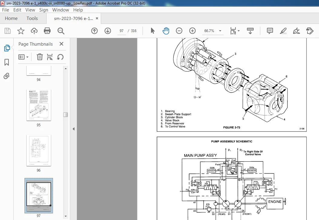
Main Pump Assembly Description . . . . . . . . . . . . . . . . . . . . . . . . . . . . . . . . . . . . . . . . . . . . . . . . . 3-43
400LC-III Shop Manual – Revision 1
Pump Regulator Description . . . . . . . . . . . . . . . . . . . . . . . . . . . . . . . . . . . . . . . . . . . . . . . . . . . . . 3-46
Hydraulic System General Precautions . . . . . . . . . . . . . . . . . . . . . . . . . . . . . . . . . . . . . . . . . . . . . 3-51
Maintenance Service and Repair Procedure . . . . . . . . . . . . . . . . . . . . . . . . . . . . . . . . . . . . . . . . . 3-52
Troubleshooting – Main Pump . . . . . . . . . . . . . . . . . . . . . . . . . . . . . . . . . . . . . . . . . . . . . . . . . . . . 3-52
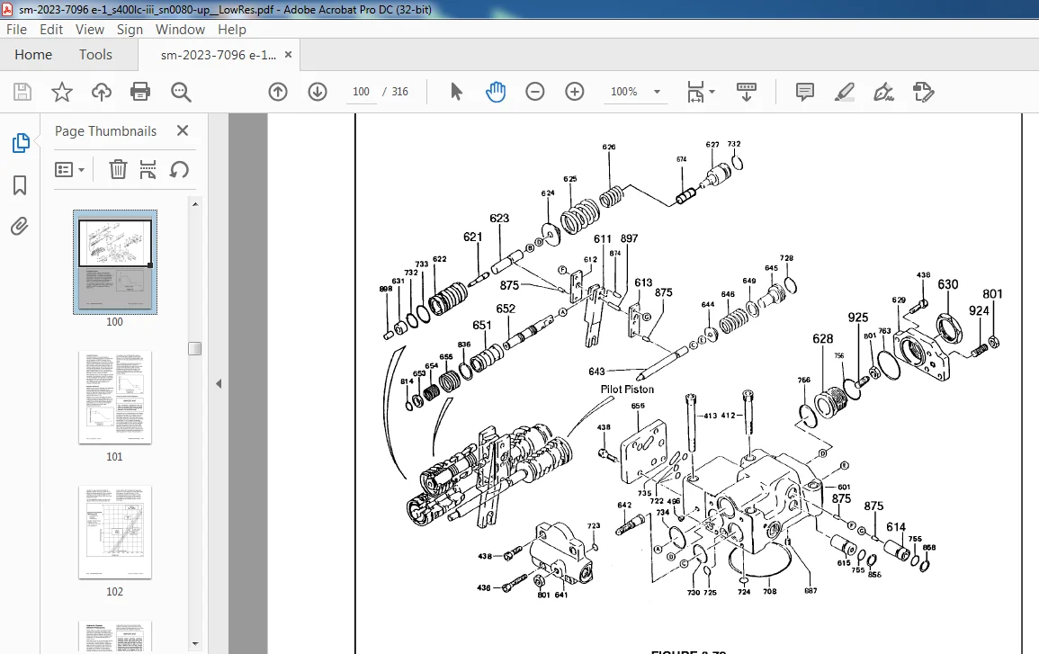
Main Pump Parts List . . . . . . . . . . . . . . . . . . . . . . . . . . . . . . . . . . . . . . . . . . . . . . . . . . . . . . . . . . 3-53
Main Pump Disassembly and Reassembly ……………………………………. 3-54
Reassembly of Main Pumps and Valve Block ………………………………….. 3-57
Pump Regulator Parts List . . . . . . . . . . . . . . . . . . . . . . . . . . . . . . . . . . . . . . . . . . . . . . . . . . . . . . . 3-60
Pump Regulator Disassembly and Reassembly . . . . . . . . . . . . . . . . . . . . . . . . . . . . . . . . . . . . . . . 3-62
Swing Motor Basic Operation . . . . . . . . . . . . . . . . . . . . . . . . . . . . . . . . . . . . . . . . . . . . . . . . . . . . . 3-66
Rebuilding the Swing Motor – Disassembly . . . . . . . . . . . . . . . . . . . . . . . . . . . . . . . . . . . . . . . . . . 3-69
Swing Motor Parts List …………………………………………………. 3-70
Rebuilding the Swing Motor – Assembly . . . . . . . . . . . . . . . . . . . . . . . . . . . . . . . . . . . . . . . . . . . . 3-74
Swing Gearbox Disassembly . . . . . . . . . . . . . . . . . . . . . . . . . . . . . . . . . . . . . . . . . . . . . . . . . . . . 3-80
Swing Gearbox – Assembly . . . . . . . . . . . . . . . . . . . . . . . . . . . . . . . . . . . . . . . . . . . . . . . . . . . . . . 3-84
Control Valve Assembly . . . . . . . . . . . . . . . . . . . . . . . . . . . . . . . . . . . . . . . . . . . . . . . . . . . . . . . . 3-88
Pump Flow Control Regulator . . . . . . . . . . . . . . . . . . . . . . . . . . . . . . . . . . . . . . . . . . . . . . . . . . . . 3-104
Electronic Proportional Control Valve ……………………………………….. 3-105
LOWER STRUCTURE
General Description . . . . . . . . . . . . . . . . . . . . . . . . . . . . . . . . . . . . . . . . . . . . . . . . . . . . . . . . . . . . 4-1
Travel Motor – Theory of Operation . . . . . . . . . . . . . . . . . . . . . . . . . . . . . . . . . . . . . . . . . . . . . . . . 4-2
Travel Motor Brake . . . . . . . . . . . . . . . . . . . . . . . . . . . . . . . . . . . . . . . . . . . . . . . . . . . . . . . . . . . . . 4-2
Counterbalance Valve …………………………………………………. 4-2
Relief Valve . . . . . . . . . . . . . . . . . . . . . . . . . . . . . . . . . . . . . . . . . . . . . . . . . . . . . . . . . . . . . . . . . . 4-2
Travel Motor Specifications . . . . . . . . . . . . . . . . . . . . . . . . . . . . . . . . . . . . . . . . . . . . . . . . . . . . . . 4-3
Travel Motor . . . . . . . . . . . . . . . . . . . . . . . . . . . . . . . . . . . . . . . . . . . . . . . . . . . . . . . . . . . . . . . . . . 4-4
Principles of Torque Generation . . . . . . . . . . . . . . . . . . . . . . . . . . . . . . . . . . . . . . . . . . . . . . . . . . . 4-4
Two Speed Travel …………………………………………………….. 4-4
Motor Rotation . . . . . . . . . . . . . . . . . . . . . . . . . . . . . . . . . . . . . . . . . . . . . . . . . . . . . . . . . . . . . . . . 4-5
Motor Lubrication . . . . . . . . . . . . . . . . . . . . . . . . . . . . . . . . . . . . . . . . . . . . . . . . . . . . . . . . . . . . . . 4-5
Hydraulic Oil Visual Inspection ………………………………………….. 4-5
Filter . . . . . . . . . . . . . . . . . . . . . . . . . . . . . . . . . . . . . . . . . . . . . . . . . . . . . . . . . . . . . . . . . . . . . . . 4-6
Motor Installation and Inspection . . . . . . . . . . . . . . . . . . . . . . . . . . . . . . . . . . . . . . . . . . . . . . . . . . 4-6
Troubleshooting – Travel Motor ……………………………………………. 4-7
Troubleshooting – Travel Brake . . . . . . . . . . . . . . . . . . . . . . . . . . . . . . . . . . . . . . . . . . . . . . . . . . . . 4-8
Troubleshooting – Relief Valve . . . . . . . . . . . . . . . . . . . . . . . . . . . . . . . . . . . . . . . . . . . . . . . . . . . . 4-8
Troubleshooting – Dual Counterbalance Valve …………………………………. 4-9
Troubleshooting – Two Speed Shift Valve …………………………………….. 4-9
Travel Motor Repair Standards ……………………………………………. 4-10
Rebuilding the Travel Motor – Disassembly (MAG-230-VP6000-3) . . . . . . . . . . . . . . . . . . . . . . . . . 4-11
Travel Motor Assembly Torques …………………………………………… 4-16
Rebuilding the Travel Motor – Assembly . . . . . . . . . . . . . . . . . . . . . . . . . . . . . . . . . . . . . . . . . . . . . 4-16
Travel Gearbox – (Model RGC-230 VP-61) . . . . . . . . . . . . . . . . . . . . . . . . . . . . . . . . . . . . . . . . . . . 4-22
Rebuilding the Travel Gearbox – Disassembly . . . . . . . . . . . . . . . . . . . . . . . . . . . . . . . . . . . . . . . . 4-22
Travel Gearbox Parts List . . . . . . . . . . . . . . . . . . . . . . . . . . . . . . . . . . . . . . . . . . . . . . . . . . . . . . . . 4-23
Rebuilding the Travel Gearbox Assembly . . . . . . . . . . . . . . . . . . . . . . . . . . . . . . . . . . . . . . . . . . . 4-26
Front Idler Roller Parts List . . . . . . . . . . . . . . . . . . . . . . . . . . . . . . . . . . . . . . . . . . . . . . . . . . . . . . 4-32
Lower Roller Parts List . . . . . . . . . . . . . . . . . . . . . . . . . . . . . . . . . . . . . . . . . . . . . . . . . . . . . . . . . . 4-35
Upper Roller Parts List . . . . . . . . . . . . . . . . . . . . . . . . . . . . . . . . . . . . . . . . . . . . . . . . . . . . . . . . . . 4-37
Track Spring and Track Adjusting Cylinder Parts List . . . . . . . . . . . . . . . . . . . . . . . . . . . . . . . . . . . 4-40
Track Tensioning …………………………………………………….. 4-41
Service Standards for Lower Travel Frame Components . . . . . . . . . . . . . . . . . . . . . . . . . . . . . . . . . 4-42
400LC-III Shop Manual Revision 1
ELECTRICAL SYSTEM
General Description . . . . . . . . . . . . . . . . . . . . . . . . . . . . . . . . . . . . . . . . . . . . . . . . . . . . . . . . . . . . 5-1
24 Volt Operation . . . . . . . . . . . . . . . . . . . . . . . . . . . . . . . . . . . . . . . . . . . . . . . . . . . . . . . . . . . . . . 5-2
Engine Start-up and Shutdown . . . . . . . . . . . . . . . . . . . . . . . . . . . . . . . . . . . . . . . . . . . . . . . . . . . 5-3
Cylinder Preheat – Intake Air Electrical Heater …………………………………. 5-4
Alternator Circuit . . . . . . . . . . . . . . . . . . . . . . . . . . . . . . . . . . . . . . . . . . . . . . . . . . . . . . . . . . . . . . 5-5
Low Current Electrical Circuits ……………………………………………. 5-7
Climate Control (Air Conditioning) Circuit . . . . . . . . . . . . . . . . . . . . . . . . . . . . . . . . . . . . . . . . . . . . 5-9
Power Mode System Operating Components . . . . . . . . . . . . . . . . . . . . . . . . . . . . . . . . . . . . . . . . . 5-11
Instrument Panel …………………………………………………….. 5-12
Instrument Panel LED Displays and Input Terminal Connections . . . . . . . . . . . . . . . . . . . . . . . . . . 5-14
Instrument Panel Connector Arrangement ……………………………………. 5-14
Instrument Panel Selector Switches ………………………………………… 5-15
Instrument Panel Coolant Overheating Circuit …………………………………. 5-15
Instrument Panel Indicator Lights . . . . . . . . . . . . . . . . . . . . . . . . . . . . . . . . . . . . . . . . . . . . . . . . . . 5-15
Instrument Panel Engine Oil Pressure Circuit . . . . . . . . . . . . . . . . . . . . . . . . . . . . . . . . . . . . . . . . . 5-16
Start-up Electrical Test Circuit . . . . . . . . . . . . . . . . . . . . . . . . . . . . . . . . . . . . . . . . . . . . . . . . . . . . 5-16
Interior Lighting . . . . . . . . . . . . . . . . . . . . . . . . . . . . . . . . . . . . . . . . . . . . . . . . . . . . . . . . . . . . . . . 5-16
Hydraulic Pump Discharge Pressure Sensor ………………………………….. 5-16
Power Mode Circuit Instrument Panel Summary . . . . . . . . . . . . . . . . . . . . . . . . . . . . . . . . . . . . . . . 5-18
Power Mode System Basic Operation . . . . . . . . . . . . . . . . . . . . . . . . . . . . . . . . . . . . . . . . . . . . . . 5-19
Power Mode Ill ……………………………………………………… 5-20
Power Mode 11 • • • • • • • • • • • • • • • • • • • • • • • • • • • • • • • • • • . • • . • • . • • . • • . • • . • • . . • . . • • • • • • . 5-23
Power Mode I . . . . . . . . . . . . . . . . . . . . . . . . . . . . . . . . . . . . . . . . . . . . . . . . . . . . . . . . . . . . . . . . 5-24
Swing Priority Circuit ………………………………………………….. 5-25
Boom Up, Arm Crowd, and Bucket Crowd Combined Operation . . . . . . . . . . . . . . . . . . . . . . . . . . . 5-26
Loading Work Mode . . . . . . . . . . . . . . . . . . . . . . . . . . . . . . . . . . . . . . . . . . . . . . . . . . . . . . . . . . . . 5-27
Swing and Arm Dump Combined Operation . . . . . . . . . . . . . . . . . . . . . . . . . . . . . . . . . . . . . . . . . . 5-28
Swing Priority and Arm Crowd Recovery Function ………………………………. 5-29
Leveling Mode I: Boom Up and Arm Crowd Combined Operation …………………….. 5-30
Leveling Mode II …………………………………………………….. 5-31
Maintaining Straight Travel While Swinging . . . . . . . . . . . . . . . . . . . . . . . . . . . . . . . . . . . . . . . . . . . 5-32
Maintaining Straight Travel While Operating the Boom Arm, or Bucket Cylinders . . . . . . . . . . . . . . . 5-33
ENGINE
Engine Specifications (D2366T) …………………………………………… 6-1
Wear Limits of Major Engine Components . . . . . . . . . . . . . . . . . . . . . . . . . . . . . . . . . . . . . . . . . . . 6-1
Engine Oil Pump Overhaul and Rebuilding . . . . . . . . . . . . . . . . . . . . . . . . . . . . . . . . . . . . . . . . . . . 6-6
Fuel Injection Pump Installation, Alignment and Timing …………………………… 6-8
Cylinder Headbolt Torque Requirements . . . . . . . . . . . . . . . . . . . . . . . . . . . . . . . . . . . . . . . . . . . . 6-1 o
Engine Throttle Controller . . . . . . . . . . . . . . . . . . . . . . . . . . . . . . . . . . . . . . . . . . . . . . . . . . . . . . . 6-11
Engine Speed Sensor …………………………………………………. 6-13
INSPECTION, MAINTENANCE AND ADJUSTMENT
Periodic Inspection and Maintenance ……………………………………….. 7-1
Table of Recommended Lubricants . . . . . . . . . . . . . . . . . . . . . . . . . . . . . . . . . . . . . . . . . . . . . . . . 7-2
Maintenance Intervals …………………………………………………. 7-3
Inspection and Maintenance …………………………………………….. 7-4
Daily or Every 1 O Operating Hours . . . . . . . . . . . . . . . . . . . . . . . . . . . . . . . . . . . . . . . . . . . . . . . . . 7-4
Weekly or Every 50 Operating Hours ……………………………………….. 7-7
150 Operating Hours ………………………………………………….. 7-1 O
Monthly or Every 250 Operating Hours ……………………………………… 7-10
Three Months or Every 500 Operating Hours . . . . . . . . . . . . . . . . . . . . . . . . . . . . . . . . . . . . . . . . . 7-13
Six Months or Every 1,000 Operating Hours . . . . . . . . . . . . . . . . . . . . . . . . . . . . . . . . . . . . . . . . . 7-14
400LC-III Shop Manual Revision 1 iii
General Maintenance Procedures …………………………………………. 7-16
Engine Speed Control Adjustment . . . . . . . . . . . . . . . . . . . . . . . . . . . . . . . . . . . . . . . . . . . . . . . . . 7-17
Torque Specifications ………………………………………………….. 7-18
Torque Wrench Extension Tools . . . . . . . . . . . . . . . . . . . . . . . . . . . . . . . . . . . . . . . . . . . . . . . . . . . 7-19
Flange and Thread Sealant Assembly Compounds ……………………………… 7-21
Welding Maintenance Procedures …………………………………………. 7-23
Hydraulic System Cleanliness and Oil Leaks . . . . . . . . . . . . . . . . . . . . . . . . . . . . . . . . . . . . . . . . . 7-24
Reference Notes for Electrical Schematic …………………………………….. 7-25
TESTING, TROUBLESHOOTING AND ADJUSTING
Troubleshooting Recommendations . . . . . . . . . . . . . . . . . . . . . . . . . . . . . . . . . . . . . . . . . . . . . . . . 8-1
Pilot Pressure . . . . . . . . . . . . . . . . . . . . . . . . . . . . . . . . . . . . . . . . . . . . . . . . . . . . . . . . . . . . . . . . 8-2
Power Mode Valve . . . . . . . . . . . . . . . . . . . . . . . . . . . . . . . . . . . . . . . . . . . . . . . . . . . . . . . . . . . . . 8-3
Boom/Swing Priority ………………………………………………….. 8-4
Pump Input Power Control . . . . . . . . . . . . . . . . . . . . . . . . . . . . . . . . . . . . . . . . . . . . . . . . . . . . . . . 8-5
Flow Meter and Flow Meter Kit Installation and Testing ……………………………. 8-7
Swing System Troubleshooting . . . . . . . . . . . . . . . . . . . . . . . . . . . . . . . . . . . . . . . . . . . . . . . . . . . . 8-8
Troubleshooting – Swing ……………………………………………….. 8-1 O
Troubleshooting Swing Gearbox …………………………………………. 8-11
Troubleshooting – Hydraulic Problems ………………………………………. 8-12
Troubleshooting – Control Valve . . . . . . . . . . . . . . . . . . . . . . . . . . . . . . . . . . . . . . . . . . . . . . . . . . . 8-14
Troubleshooting – Travel Control Valve ………………………………………. 8-16
Troubleshooting – Joystick Control Valve . . . . . . . . . . . . . . . . . . . . . . . . . . . . . . . . . . . . . . . . . . . . 8-17
Troubleshooting Engine Problems ………………………………………… 8-18
Troubleshooting Electrical System . . . . . . . . . . . . . . . . . . . . . . . . . . . . . . . . . . . . . . . . . . . . . . . . 8-22
EPOS-111 Self-diagnostic Codes …………………………………………… 8-23
Engine Throttle Controller . . . . . . . . . . . . . . . . . . . . . . . . . . . . . . . . . . . . . . . . . . . . . . . . . . . . . . . 8-25
DAEWOO DOOSAN SOLAR 400LC-III SHOP MANUAL 2023-7096E-1 – PDF DOWNLOAD:
IMAGES PREVIEW OF THE MANUAL:
PLEASE NOTE:
- This is not a physical manual but a digital manual – meaning no physical copy will be couriered to you. The manual can be yours in the next 2 mins as once you make the payment, you will be directed to the download page IMMEDIATELY.
- This is the same manual used by the dealers inorder to diagnose your vehicle of its faults.
- Require some other service manual or have any queries: please WRITE to us at [email protected]
M.A