Daewoo Wheel Loader Mega 300-III Service Manual – PDF DOWNLOAD
Original price was: $56.95.$21.95Current price is: $21.95.
Daewoo Wheel Loader Mega 300-III Service Manual – PDF DOWNLOAD
Description
Daewoo Wheel Loader Mega 300-III Service Manual – PDF DOWNLOAD
DESCRIPTION:
Daewoo Wheel Loader Mega 300-III Service Manual – PDF DOWNLOAD
General Safety Essentials Accessory Applications :
- The wheel loader has been designed primarily for moving earth with a bucket. For use as a grapple or for other object handling, contact Daewoo. Liftingwork applications are permitted in approved lift configuration, to rated capacity only, with no sideloading (unless prohibited by local regulation). DO NOT use the machine for activities for which it was not intended. DO NOT use the bucket for lifting work, unless lift slings are used in the approved configuration.
- Working in rough terrain, use of an accessory hydraulic hammer (breaker), demolition applications, or other hazardous operation may require installation of additional protective structures to safeguard the operator.
Static Tipping Load:
The machine can lift a maximum of 14,500 kg (31,967 lb) with the bucket in the Straight Ahead position, and a maximum of 12,000 kg (26,455 lb) with the bucket in the Fully Turned position. Hooks and slings must be attached to an eye that is in the center of the bucket. All lifts must be made with the machine standing on a firm and level surface. Loads must be balanced and supported evenly. Use taglines to keep the load steady if wind conditions and large surface area are a problem. Work crew hand signals, individual tasks and safe procedures should all be universally understood before the lift is made.
TABLE OF CONTENTS:
Daewoo Wheel Loader Mega 300-III Service Manual – PDF DOWNLOAD
SAFETY
To the Operator of a Daewoo Wheel Loader 1-1
Basic Wheel Loader Operating Safety 1-1
General Safety Essentials 1-1
Locations of Safety Labels 1-2
Summary of Safety Precautions for Lifting 1-5
Operation 1-7
Equipment 1-10
Maintenance 1-11
Shipping and Transportation 1-13
SPECIFICATIONS
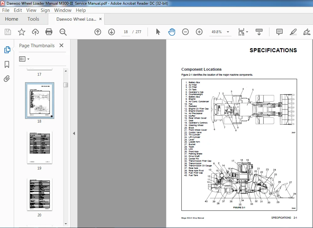
Component Locations 2-1
General Specifications 2-2
Excavator Engine Specifications 2-3
Engine Performance Curves 2-4
Working Range and Dimensions 2-5
Working Capacities 2-7
Approximate Weight of Workload Materials 2-8
INSPECTION, MAINTENANCE AND ADJUSTMENT
Preventive Maintenance 3-1
Safety Precautions 3-1
Maintenance Intervals 3-2
Table of Recommended Lubricants 3-3
Inspection and Maintenance 3-4
Daily or Every 10 Operating Hours 3-7
Weekly or Every 50 Operating Hours 3-10
Every 250 Operating Hours 3-12
Every 500 Operating Hours 3-13
Every 1,000 Operating Hours 3-13
Every 1,500 Operating Hours 3-18
Annually or Every 2,000 Operating Hours 3-18
Severe Conditions Maintenance 3-20
General Maintenance 3-21
Check Hydraulic Pressures 3-22
Tires and Wheels 3-25
Electrical System 3-26
Bolt Torque Chart 3-27
Long Term Storage 3-28
TORQUE CONVERTER AND TRANSMISSION
Drive Train 4-1
Transmission 4-2
Transmission Troubleshooting 4-5
Control Valve 4-7
Second Gear Valve 4-12
Transmission WG-180 Control Valve 4-18
Transmission Disassembly 4-21
Mega 300-III Shop Manual i
TABLE OF CONTENTS
ii Mega 300-III Shop Manual
Transmission Assembly 4-42
Power Disengagement Gearbox 4-82
Differential Type Output Gearing 4-87
WK Torque Converter 4-98
WK Converter Clutch Valve 4-109
POWER STEERING
Power Steering System 5-1
Steering System Troubleshooting 5-5
Steering Unit 5-6
Priority Valve 5-19
AXLES
Front and Rear Axles 6-1
Axle Troubleshooting 6-2
Front Axle Housing 6-3
Axle Differential 6-4
Planetary Gear Set 6-7
Parking Brake 6-9
Rear Axle 6-11
Brake System 6-13
HYDRAULIC SYSTEM
Hydraulic Circuits Description 7-1
Hydraulic Pump 7-3
Hydraulic Circuits and Components 7-18
Manually Controlled Pilot Valve 7-23
Automatic Bucket Return-to-Dig System 7-24
Automatic Boom Kick-out System 7-25
Automatic Boom Float System 7-25
Hydraulic Cylinders 7-27
Accumulator 7-40
Hydraulic System Schematic 7-45
ENGINE
Engine Specifications (D2366T) 8-1
Valve Adjustment Sequence 8-2
Engine Cylinder Compression Test 8-2
Wear Limits of Major Engine Components 8-2
Engine Oil Pump Overhaul and Rebuilding 8-7
Fuel Injection Pump Installation, Alignment and Timing 8-9
Cylinder Head Bolt Torque Requirements 8-11
ELECTRICAL SYSTEM
Electrical Schematic 9-1
24 Volt Operation 9-1
Wiring Color Code for Electrical Schematic Diagrams 9-1
Engine Start Circuit 9-2
Engine Stop Motor 9-4
Engine Intake Preheat Circuit 9-6
Windshield Wiper Circuit 9-8
Electrical System Schematic 9-11
INDEX 10-1
DAEWOO WHEEL LOADER MEGA 300-III SERVICE MANUAL – PDF DOWNLOAD:
IMAGES PREVIEW OF THE MANUAL:
PLEASE NOTE:
- This is the SAME exact manual used by your dealers to fix your vehicle.
- The same can be yours in the next 2-3 mins as you will be directed to the download page immediately after paying for the manual.
- Any queries / doubts regarding your purchase, please feel free to contact [email protected]