Daihatsu Terios J100 Service Manual – PDF DOWNLOAD
$36.95
Daihatsu Terios J100 Service Manual – PDF DOWNLOAD
PN 9710-JE
Description
Daihatsu Terios J100 Service Manual – PDF DOWNLOAD
FILE DETAILS:
Daihatsu Terios J100 Service Manual – PDF DOWNLOAD
PN 9710-JE
Language : English
Pages : 1009
Downloadable : Yes
File Type : PDF
IMAGES PREVIEW OF THE MANUAL:
TABLE OF CONTENTS:
Daihatsu Terios J100 Service Manual – PDF DOWNLOAD
PN 9710-JE
AUTOMATIC TRANSMISSION
OUTLINE AT– 2
SECTIONAL VIEW OF AUTOMATIC
TRANSMISSION AT– 2
SPECIFICATIONS AT– 3
TORQUE CONVERTERAT– 4
CONSTRUCTION AT– 4
OPERATION AT– 4
POWER TRAIN MECHANISMAT– 5
DESCRIPTION AT– 5
CONSTRUCTION AT– 5
OPERATION AT– 6
HYDRAULIC PRESSURE CONTROL
SYSTEMAT–11
DESCRIPTION AT–11
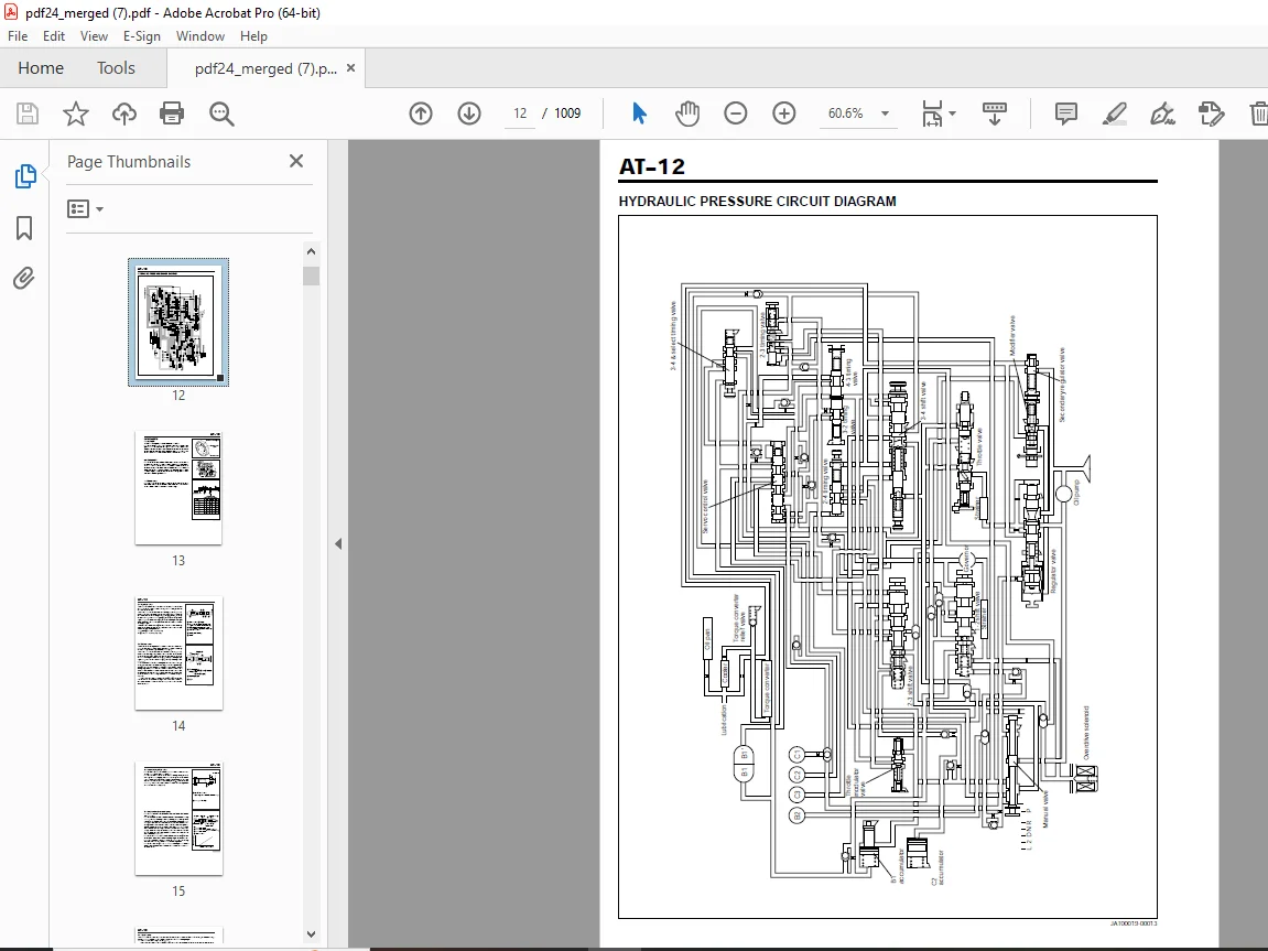
HYDRAULIC PRESSURE CIRCUIT
DIAGRAM AT–12
COMPONENTS AT–13
CASE & COVER AT–25
DESCRIPTION AT–25
ELECTRIC CONTROL SYSTEM AT–26
OVERDRIVE SWITCH AT–26
SHIFT CONTROL MECHANISM AT–27
DESCRIPTION AT–27
COMPONENTS AT–27
PRELIMINARY CHECKAT–28
TESTING AT–32
STALL TEST AT–32
TIME LAG TEST AT–33
HYDRAULIC PRESSURE TEST AT–33
RUNNING TEST AT–37
ELECTRIC–RELATED TESTS AT–38
REMOVAL AND INSTALLATION OF
AUTOMATIC TRANSMISSIONAT–40
COMPONENTS AT–40
CONNECTION AND DISCONNECTION
OF OIL COOLER HOSES AT–44
COMPONENTS AT–44
DISASSEMBLY AND ASSEMBLY OF
AUTOMATIC TRANSMISSIONAT–46
COMPONENTS AT–46
COMPONENTS (INNER PARTS) AT–47
REMOVAL AT–48
DISASSEMBLY AND ASSEMBLY OF
COMPONENTS AT–61
INSPECTION AT–63
ASSEMBLY AT–67
INSTALLATION AND REMOVAL
OF CONTROL CABLE AND
FLOOR SHIFTAT–90
COMPONENTS AT–90
APPENDIXAT–92
SSTs (Special Service Tools) AT–92
SERVICE SPECIFICATIONS AT–94
TIGHTENING TORQUEAT–95
BODY ELECTRICAL SYSTEM
DAIHATSU
BE
NO9710-JE
J100
GENERAL DESCRIPTION BE– 2
POWER SUPPLY BE– 6
IGNITION KEY SWITCHBE– 8
COMBINATION METER BE– 9
HEAD LAMP BE– 15
HEAD LAMP LEVELINGBE– 18
FRONT FOG LAMP BE– 19
STOP LAMP BE– 20
BACK UP LAMP BE– 21
REAR FOG LAMPBE– 22
TAIL LAMP & LICENSE PLATE LAMP BE– 24
INTERIOR LAMP & LUGGAGE ROOM
LAMP BE– 25
HAZARD WARNING & HORN BE– 27
HATER & VENTILATIONBE– 29
POWER DOOR LOCK BE– 32
POWER WINDOWBE– 34
WIPER & WASHER BE– 36
DEFOGGER BE– 39
CIGARETTE LIGHTER BE– 41
REAR VIEW MIRROR BE– 43
ITC SYSTEM BE– 45
SRS AIR BAG SYSTEM BE– 52
IMMOBILIZER SYSTEMBE– 91
SSTs (Special service tools) BE–104
TIGHTENING TORQUE BE–104
BODY
ALIGNMENT ADJUSTMENTS BO– 2
FRONT BUMPER BO– 7
FRONT FENDER BO–11
REAR BUMPERBO–13
FENDER LINERBO–16
HOOD & HOOD LOCK CONTROL
CABLEBO–18
FUEL LID OPENER BO–22
ROOF DRIP MOLDING BO–24
ROOF RAIL & ROOF END SPOILER BO–25
REMOVABLE ROOF BO–28
INSTRUMENT PANELBO–30
FRONT SEAT BO–37
REAR SEAT BO–39
SEAT BELT BO–40
FRONT DOOR BO–44
REAR DOORBO–52
BACK DOORBO–59
TRIM & GARNISH BO–64
WINDOWS BO–70
FUEL TANK BO–82
ACCELERATOR PEDAL BO–91
EXHAUST PIPEBO–93
ENGINE MOUNTING INSULATOR BO–94
TIGHTENING TORQUE BO–96
BRAKES
BASIC CHECK BR– 2
BRAKE PEDAL BR– 5
BRAKE MASTER CYLINDER BR– 7
BRAKE BOOSTERBR–13
FRONT BRAKE BR–16
REAR BRAKE BR–22
PARKING BRAKE BR–30
PROPORTIONING VALVE BR–33
BRAKE HOSE BR–34
ANTI-LOCK BRAKE SYSTEM BR–36
JABS CIRCUIT DIAGNOSIS BR–37
ABS RELATED CONNECTORS BR–38
ABS CIRCUIT CONNECTION TABLE BR–40
PRECAUTIONS BR–42
TROUBLE SHOOTING HINTS BR–44
HOW TO PROCEED TROUBLE
SHOOTING BR–45
DIAGNOSIS CODE CHECKBR–46
UNIT INSPECTION & REPLACEMENT BR–70
TIGHTENING TORQUE BR–91
SSTs BR–92
CHARGING SYSTEM
OUTLINE OF CHARGING SYSTEM CH– 2
CHARGING SYSTEM CIRCUIT CH– 2
PRECAUTIONS CH– 3
IN-VEHICLE INSPECTION CH– 3
ALTERNATOR CH– 9
SERVICE SPECIFICATIONSCH–22
TROUBLE SHOOTING CH–22
CLUTCH
OUTLINE CL– 2
CLUTCH SECTIONAL VIEW CL– 2
CLUTCH PEDAL ADJUSTMENT CL– 3
PEDAL INSTALLATION HEIGHTCL– 3
ADJUSTMENT OF CLUTCH PEDAL
FREE TRAVELCL– 3
CLUTCH PEDAL & CLUTCH CABLE CL– 4
1Main points of clutch pedal
installationCL– 6
2Main points of clutch cable
installationCL– 6
CLUTCH RELEASE MECHANISM CL– 7
COMPONENTS CL– 7
1Operation prior to removalCL– 7
2Main points of removal CL– 7
3Check CL– 8
4Main points of installation CL– 9
5Operation after installationCL–11
APPENDIX CL–12
SSTs (Special Service Tools) CL–12
SERVICE SPECIFICATIONS CL–12
TIGHTENING TORQUE CL–12
COOLING SYSTEM
DESCRIPTION CO– 2
RADIATOR CO– 3
RADIATOR CAP CO– 3
RADIATOR RESERVE TANK CO– 3
RADIATOR HOSES & PIPES CO– 4
FAN-EQUIPPED
FLUID COUPLING CO– 5
COOLING FAN CO– 5
FLUID COUPLING WITH FAN CO– 5
WATER PUMP PULLEYCO– 6
THERMOSTAT CO– 7
PRECAUTIONS CO– 8
CHECK & CHANGE OF
ENGINE COOLANT CO– 8
WATER PUMP CO–10
COMPONENTS CO–10
REMOVAL OF WATER PUMPCO–10
INSPECTION OF WATER
PUMP-RELATED PARTS CO–11
INSTALLATION OF
WATER PUMPCO–11
THERMOSTAT CO–13
REMOVAL OF THERMOSTATCO–13
INSPECTION OF
THERMOSTATCO–13
INSTALLATION OF
THERMOSTATCO–14
RADIATOR CO–15
CLEANING OF RADIATOR CO–15
INSPECTION OF RADIATOR CO–15
REMOVAL OF RADIATORCO–16
INSTALLATION OF RADIATOR CO–17
TIGHTENING TORQUE CO–19
SERVICE SPECIFICATION CO–19
FRONT & REAR DIFFERENTIAL
FRONT DIFFERENTIAL DF– 2
COMPONENTS DF– 2
REAR DIFFERENTIALDF– 3
COMPONENTS DF– 3
IN-VEHICLE SERVICEDF– 4
REPLACEMENT OF FRONT AND
REAR DIFFERENTIAL COMPANION
FLANGE OIL SEALS DF– 4
REPLACEMENT OF FRONT
DIFFERENTIAL SIDE OIL SEAL DF– 7
REMOVALDF– 9
DISASSEMBLY DF–11
INSPECTIONDF–16
ASSEMBLY DF–18
INSTALLATION DF–25
SSTs DF–28
TIGHTENING TORQUE DF–30
EMISSION CONTROL SYSTEMS
COMPONENT LAYOUT EC– 2
POSITIVE CRANKCASE VENTILATION
SYSTEM EC– 3
INSPECTION OF PCV HOSE &
CONNECTION EC– 4
FUEL EVAPORATIVE EMISSION
CONTROL SYSTEM EC– 5
DASHPOT (DP) SYSTEM (only for
automatic transmission models) EC– 8
THREE-WAY CATALYST (TWC)
SYSTEM EC–10
INSPECTION OF EXHAUST PIPE
ASSEMBLY EC–10
INSPECTION OF HEAT INSULATOR EC–10
THREE-WAY CATALYST EC–11
SST (Special Service Tools)EC–13
TIGHTENING TORQUE EC–13
SERVICE SPECIFICATIONSEC–13
FRONT AXLE & SUSPENSION
WHEEL ALIGNMENT FS– 2
PREPARATION FS– 2
FRONT AXLE AND SUSPENSION FS– 4
COMPONENTS FS– 4
FRONT AXLEFS– 5
REMOVAL FS– 5
DISASSEMBLY FS– 7
INSPECTION FS– 8
ASSEMBLY FS– 9
INSTALLATION FS–10
FRONT STABILIZER BARFS–12
REMOVAL FS–12
DISASSEMBLY FS–12
INSPECTION FS–12
ASSEMBLY FS–13
INSTALLATION FS–13
SHOCK ABSORBER AND
SPRINGFS–14
REMOVAL FS–14
DISASSEMBLY FS–14
INSPECTION FS–15
ASSEMBLY FS–15
INSTALLATION FS–16
SUSPENSION LOWER ARM FS–17
REMOVAL FS–17
INSPECTION FS–17
REPLACEMENT OF SUSPENSION
LOWER ARM BUSH FS–18
REPLACEMENT OF SUSPENSION
LOWER ARM BALL JOINT
DUST COVER FS–18
INSTALLATION FS–19
DRIVE SHAFT FS–20
COMPONENTS FS–20
REMOVAL FS–20
DISASSEMBLY FS–21
INSPECTION FS–22
ASSEMBLY FS–23
REPLACEMENT OF TRANSFER
OIL SEAL FS–25
INSTALLATION FS–25
TIGHTENING TORQUEFS–26
GENERAL INFORMATION
IMPORTANT SAFETY NOTICE GI– 2
WARNINGS, CAUTIONS AND NOTES GI– 2
HOW TO USE THIS MANUALGI– 4
CONTENTS OF EXPLANATION GI– 4
ABBREVIATION CODES GI– 6
GENERAL SERVICE INSTRUCTION GI– 7
HANDLING INSTRUCTIONS ON
CATALYTIC CONVERTER GI– 8
JACKING POINTS AND SUPPORTING
POINTS OF SAFETY STANDSGI– 9
MODEL VARIATIONGI–13
CHASSIS SERIAL NUMBER STAMPED
POSITION GI–14
MANUFACTURER’S PLATE POSITION GI–14
CONTENTS OF MANUFACTURER’S
PLATE GI–14
ENGINE NUMBER AND ENGINE TYPE
STAMPED POSITIONS GI–15
BODY COLOR INFORMATION GI–15
COLOR CODE IN THE WORLD GI–16
TRIM CODE GI–16
IGNITION SYSTEM
WIRING DIAGRAM IG– 2
SPARK TEST IG– 3
SPARK PLUGIG– 3
POWER SUPPLYIG– 4
IGNITION WIRE IG– 5
IGNITION COIL IG– 5
CAM ANGLE SENSOR IG– 5
EFI ECU IG– 7
IGNITION TIMING IG– 9
TIGHTENING TORQUEIG–10
SSTs IG–10
TRANSFER
DESCRIPTION TR– 2
CENTER DIFFERENTIAL SYSTEM TR– 2
OPERATION OF CENTER
DIFFERENTIAL LOCK SYSTEM TR– 2
IN-VEHICLE INSPECTION TR– 4
COMPONENTS TR– 5
REMOVALTR– 5
DISASSEMBLY TR– 8
INSPECTIONTR–10
ASSEMBLY TR–15
INSTALLATION TR–17
SSTs TR–20
TIGHTENING TORQUE TR–20
DESCRIPTION:
Daihatsu Terios J100 Service Manual – PDF DOWNLOAD
PN 9710-JE
- In the power train mechanism, the power that has been transmitted from the engine to the input shaft of the transmission through the torque converter is transmitted from various clutches to the planetary gear, using reduction ratios optimum for the running condition.
IMPORTANT SAFETY NOTICE:
- The vehicle is a machine comprising a great number of parts. Basically speaking, the vehicle is potentially hazard. However, one can handle it safely if he has the required knowledge.
- Correct service methods and repair procedures are very vital for assuring not only the safety and reliability of a vehicle, but also the safety of service personnel concerned.
- The methods and procedures contained in this manual describe in a general way the techniques which the manufacturer has recommended. Thus, they will contribute to ensuring the reliability of the products. The contents of the servicing operations come in a wide variety of ways. Moreover, techniques, tools and parts necessary for each operation are different widely from each other.
- This manual does not cover all details of techniques, procedures, parts, tools and handling instructions which are necessary for these operations, for such coverage is impossible. Hence, any one who obtains this manual is expected first to make his responsible selection as to techniques, tools and parts which are necessary for servicing the vehicle concerned properly. Furthermore, he must assume responsibility for his actions in connection with his own safety.
- Therefore, one should not perform any service if he is not capable of making responsible selection and/or if he can not understand the contents herein described, for this manual has been prepared for experienced service personnel.
The following list describes general WARNINGS:
Always wear safety glasses for eye protection.
- · Use safety stands whenever a procedure requires you to be under the vehicle.
- · Be sure that the ignition switch is always in the OFF position, unless otherwise required by the procedure.
- · Set the parking brake when working on the vehicle.
- · Operate the engine only in a well-ventilated area to avoid the danger of carbon monoxide.
- · Keep yourself and your clothing away from moving parts, when the engine is running, especially from the fan and belts.
- · To prevent serious burns, avoid contact with hot metal parts, such as the radiator, exhaust manifold, tail pipe, catalytic converter and muffler.
- · Do not smoke while working on a vehicle. · To avoid injury, always remove rings, watches, loose hanging jewelry, and loose clothing before beginning to work on a vehicle.
- · Keep hands and other objects clear of the radiator fan blades! The electric cooling fan is mounted on the radiator and can start to operate at anytime by a rise in coolant temperature or turning ON of the air conditioner switch in the case of vehicles equipped with an air conditioner.
- The electric cooling fan is also mounted on the condenser for air conditioner and starts to operate anytime when the air conditioner switch is turned “ON”.
- For this reason care should be taken to ensure that the electric cooling fan motor is completely disconnected when working under the hood.
G.B 22/02/25