
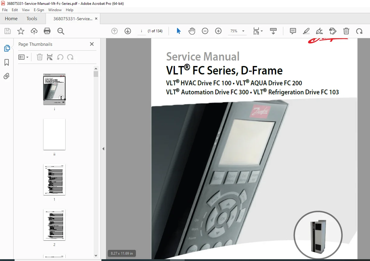
Danfoss VLT FC Series D-Frame Service Manual – Drives Repair & Tests
$65.00 Original price was: $65.00.$15.95Current price is: $15.95.
This official Danfoss VLT FC Series D-Frame service manual PDF covers VLT HVAC Drive FC 100/102, VLT AQUA Drive FC 200/202, VLT AutomationDrive FC 300/302 and VLT Refrigeration Drive FC 103. It provides complete adjustable frequency drive operation, warning/alarm fault code explanations, and detailed static and dynamic test procedures, plus full disassembly/assembly instructions and spare parts information for D-frame drives.
Description
Danfoss VLT FC Series D-Frame Service Manual – Drives Repair & Tests PDF DOWNLOAD
Description
This is the original Danfoss “Service Manual – VLT® FC Series, D-Frame (MG94A222, Rev. 2014-02-10)” for VLT HVAC Drive FC 100/102, VLT AQUA Drive FC 200/202, VLT AutomationDrive FC 300/302, and VLT Refrigeration Drive FC 103 adjustable frequency drives. It specifically covers D-Frame sizes (D1h, D2h, D3h, D4h, D5h, D6h, D7h, D8h) in the 380–500 V and 525–690 V power ranges.
368075331-Service-Manual-Vlt-Fc…
Engineers and technicians use this Danfoss VLT FC Series D-frame service manual PDF for:
Understanding internal drive operation (logic, DC bus, inverter, braking, cooling)
Interpreting warning & alarm messages and fault logs
Performing static and dynamic test procedures on rectifier, DC bus, IGBTs, fans, current sensors and more
Carrying out full disassembly and assembly of D-Frame units (D1h–D8h)
Using special test equipment such as the signal test board and split-bus supply
Identifying spare parts like DC capacitor banks, power cards, fans, gate drive cards and EMC options
The manual is written at a technical level intended for experienced service personnel and drive specialists. It pairs perfectly with the standard instruction manual and gives the deep-level diagnostics and repair information that the user/instruction manuals never show.
🗂️ Table of Contents / Bookmarks (Cleaned & Structured)
1. Introduction
368075331-Service-Manual-Vlt-Fc…
Purpose of the service manual
Product overview (HVAC, AQUA, Automation, Refrigeration drives)
Safety warnings – dangerous voltages, residual DC bus energy
Electrostatic Discharge (ESD) precautions
Frame size definitions (D1h / D2h / D3h / D4h / D5h / D6h / D7h / D8h)
Tools required (DVM, analog meter, oscilloscope, clamp meter, signal test board, etc.)
General torque tightening values (metal & plastic threads, Class A/B)
Exploded views for D3h/D4h frame sizes (location of control card, power card, IGBTs, capacitors, fans, etc.)
Power-dependent specifications (current, kVA, efficiency, power loss, fuses, cable sizes)
Warning and alarm trip points
DC voltage levels for inrush, undervoltage, overvoltage and brake activation
2. Operator Interface and Adjustable Frequency Drive Control
Introduction to drive self-diagnostics and status display
User interface overview
Graphical Local Control Panel LCP 102 (display structure, status lines, LEDs)
Numeric local control panel (NLCP)
How to operate the LCP
Status displays I, II, III (operating variables & Smart Logic Control)
Menu keys: Status, Quick Menu, Main Menu, Alarm Log
Navigation, Back, Cancel, Info, OK
Operation keys: Hand On, Off, Auto On, Reset
Changing settings with the LCP
Quick Menu vs. Main Menu
Initialization procedures (recommended and manual)
Status messages
Operation mode (Off, Auto On, etc.)
Reference source (Remote, Local)
Operation status (Ramping, Jogging, Braking, Protection mode, DC Hold, Quick Stop, Freeze Output, AMA states, etc.)
3. Internal Adjustable Frequency Drive Operation
General architecture of the drive
Description of operation
Logic section (control card, microprocessor, I/O, SMPS)
Logic-to-power interface
Power section (rectifier, DC bus, inverter)
Sequence of operation
Rectifier section (diode or SCR front-end)
Intermediate DC bus section (capacitors, inrush, DC link)
Inverter section (IGBTs, PWM, motor control)
Brake option (brake IGBT & resistor)
Cooling fans and fan speed control
Load sharing & regeneration
Specific power card connections
4. Troubleshooting
General troubleshooting tips (visual inspection, environment, wiring)
Exterior fault troubleshooting
Fault symptom troubleshooting
No display / intermittent display
Motor will not run
Incorrect motor operation
Warning and alarm messages (full list with actions)
After repair tests
5. Adjustable Frequency Drive and Motor Applications
Torque limit, current limit, unstable motor operation
Overvoltage trips
Line phase loss trips
Control logic problems
Programming problems
Motor & load-related issues
Internal adjustable frequency drive problems:
Overtemperature faults
Current sensor faults
EMI (Electromagnetic Interference)
EMI signal and power wiring
Sources and propagation of EMI
Preventive measures
Proper EMC installation
6. Test Procedures
Introduction and tools required for testing
Signal test board and extension
Access to DC bus
Static test procedures:
Pre-check precautions
Rectifier circuits test
Inverter section tests
Brake IGBT test
Intermediate section tests
IGBT temperature sensor test
Gate resistor test
Electrical fuse test
Disconnect & circuit breaker tests
Contactor test
Dynamic test procedures:
No display test
Input voltage test
Basic control card voltage test
DC bus voltage test
SMPS test
Input imbalance test
Input waveform and SCR tests
Output imbalance tests (motor voltage & current)
IGBT switching test & gate drive signal tests
Current sensor tests
Fan tests
Input terminal signal tests
After repair tests
7. Disassembly and Assembly Instructions
General notes and ESD precautions
D1h/D3h frames – disassembly/assembly:
Control card & mounting plate
Power card & mounting plate
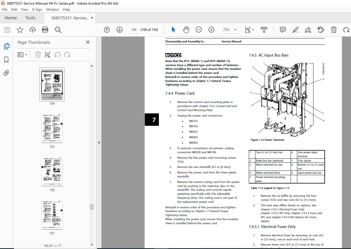
AC input bus bars (with fuses, with RFI, combination, or no options)
Line power input terminals and motor terminals
Power terminal mounting plate
Current sensors, mixing fan
Balance/high-frequency card (400 V / 690 V variants)
DC bus rails, inrush card, IGBT gate drive card
SCR input bus bars, SCRs, brake IGBT module, IGBTs
DC capacitors (400 V / 690 V)
Heatsink, door and top fans (IP20/IP21/IP54/IP54)
D2h/D4h frames – similar structure and components
D6h frames – heatsink fans and options cabinet
D8h frames – removal of drive from options cabinet, contactor and disconnect replacement
8. Special Test Equipment
Split-bus power supply (part number)
Signal test board and extension
Signal test board pin-outs
9. Spare Parts
General spare parts notes
DC capacitor bank information
10. Block Diagrams
Internal block diagrams of control and power sections
High-level functional overview for deeper diagnostics
Index
Alphabetical index (around p. 130) for rapid navigation
📄 Short File Details
| Detail | Value |
|---|---|
| Manual Name | Service Manual – VLT® FC Series, D-Frame (MG94A222) |
| Models Covered | VLT® HVAC Drive FC 100/FC 102, VLT® AQUA Drive FC 200/FC 202, VLT® AutomationDrive FC 300/FC 302, VLT® Refrigeration Drive FC 103 – D-Frame sizes (D1h–D8h) on 380–500 V and 525–690 V supplies 368075331-Service-Manual-Vlt-Fc… |
| Year / Revision | 2014 (Revision date: 2014-02-10) |
| Manual PDF Quality | High-quality OEM factory service manual; clear text, tables, warnings, diagrams and torque/spec tables |
| No. of Pages | 134 |