Danfoss VLT FC Series Variable Frequency Drive Service Manual – PDF
Original price was: $85.00.$16.95Current price is: $16.95.
Official Danfoss VLT FC Series high-power frequency converter service manual for industrial technicians. This comprehensive 209-page PDF covers complete troubleshooting, repair procedures, circuit operation, and test procedures for FC 102 (HVAC), FC 202 (AQUA), and FC 302 (AutomationDrive) models. Includes detailed disassembly instructions, component testing, EMC considerations, ratings for 380-690V systems, and dynamic/static test procedures. Essential for service engineers maintaining Danfoss variable frequency drives in HVAC, water, and industrial applications
Description
Danfoss VLT FC Series Variable Frequency Drive Service Manual FC 102 202 302 – PDF DOWNLOAD
DESCRIPTION
Danfoss VLT® FC Series High Power Frequency Converter Service Manual – Complete Professional VFD Service Reference
This is the official factory service manual for the Danfoss VLT® FC Series variable frequency drives (VFD) / frequency converters. Published in June 2008 by Danfoss (Document Number: MG.90.L1.02), this professional-grade technical documentation is essential for qualified service technicians and industrial maintenance engineers who troubleshoot, repair, and maintain these high-power motor drive systems used in HVAC, water/wastewater, and industrial automation applications.
📋 FILE DETAILS
- Manual Name: High Power Service Manual for VLT® FC Series Frequency Converters
- Drives Covered:
- VLT HVAC FC 102 – HVAC Applications
- VLT AQUA FC 202 – Water & Wastewater Applications
- VLT AutomationDrive FC 302 – Industrial Applications
- Manufacturer: Danfoss
- Publication Date: June 2008
- Document Number: MG.90.L1.02
- Total Pages: 209 pages
- File Format: PDF
- PDF Quality: High-quality official manual with detailed diagrams
- Language: English
- Page Size: A4 format
🔧 COMPREHENSIVE COVERAGE INCLUDES:
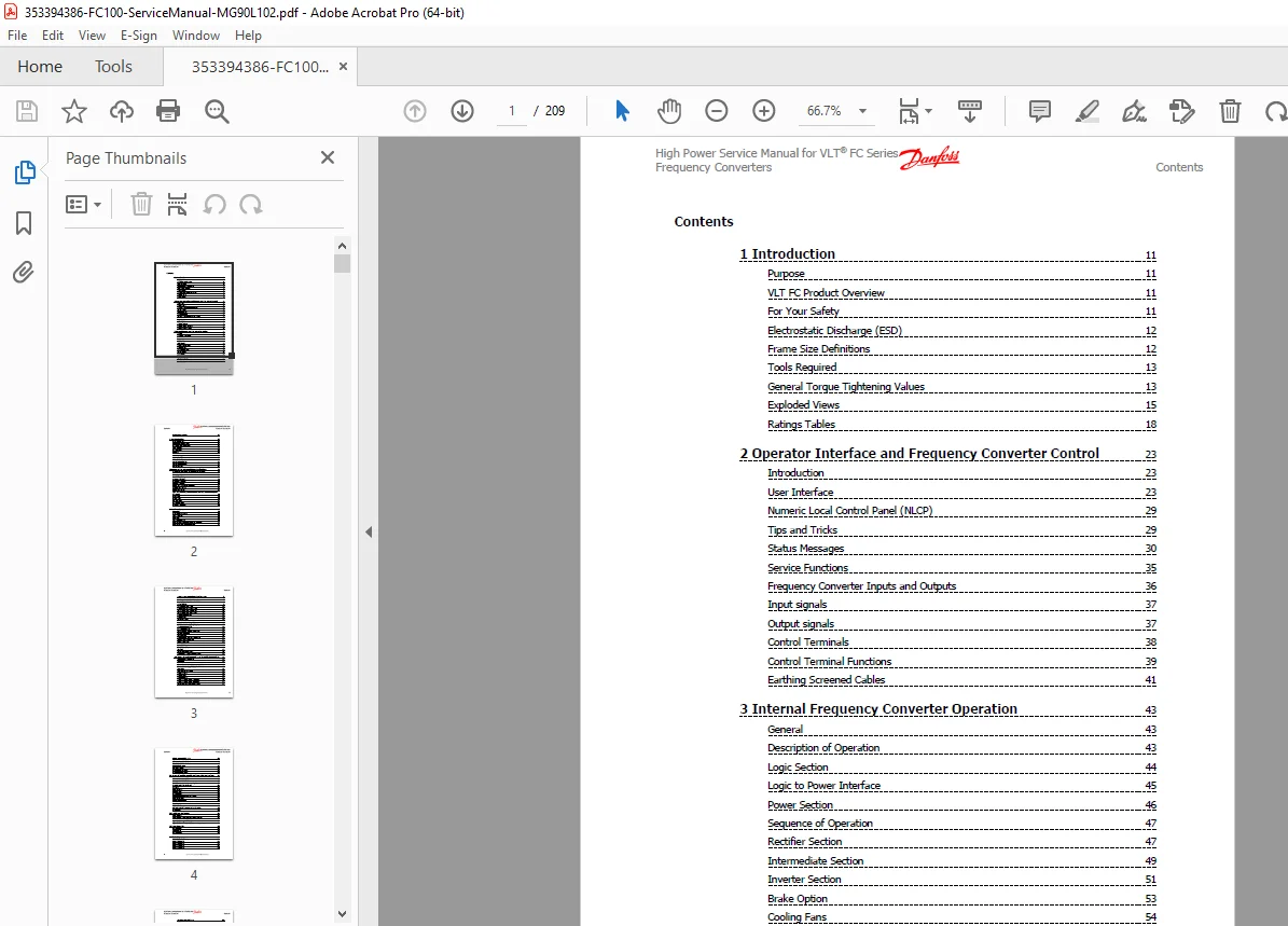
Chapter 1: Introduction (System Overview & Specifications)
Purpose:
- Service manual overview
- Intended for qualified technicians
- Fault identification procedures
- Repair methodology
VLT FC Product Overview:
VLT HVAC FC 102 Series:
- Designed for HVAC markets
- Variable torque mode operation
- Constant torque down to 15 Hz
- Special HVAC features and options
- Energy optimization
- Fan and pump applications
VLT AQUA FC 202 Series:
- Designed for water and wastewater markets
- Constant torque operation
- Variable torque capability
- Limited overload capabilities
- Pump control features
- Water treatment applications
VLT AutomationDrive FC 302 Series:
- Fully programmable drives
- Constant torque applications
- Variable torque applications
- Full-featured frequency converters
- Industrial automation
- Wide variety of control options
Voltage Ranges Covered:
- 380-480 VAC (FC 102, FC 202)
- 380-500 VAC (FC 302)
- 525-690 VAC (FC 102, FC 202)
- 525-690 VAC (FC 302 AF-650 GP)
For Your Safety:
- High voltage warnings
- Electrical shock hazards
- Motor start warnings
- Safety procedures
- Lockout/tagout requirements
Electrostatic Discharge (ESD):
- ESD sensitivity of components
- Static electricity precautions
- ESD protection procedures
- Grounding requirements
- Handling procedures
Frame Size Definitions:
- D-frame sizes (D1, D2, D3, D4)
- E-frame sizes
- Physical dimensions
- Power ratings
- Cooling configurations
Tools Required:
- Torx driver set
- Screwdrivers (various sizes)
- Multimeter
- Oscilloscope
- Torque wrenches
- Specialized test equipment
General Torque Tightening Values:
- Fastener specifications
- Torque requirements
- Connection tightening
- Bus bar torques
- Terminal torques
Exploded Views:
- Complete drive assembly
- Component locations
- Service access points
- Mounting arrangements
Ratings Tables:
- Table 1.1: FC 102 and FC 202 380-480 VAC ratings
- Table 1.2: FC 302 380-500 VAC ratings
- Table 1.3: FC 102 and FC 202 525-690 VAC ratings
- Table 1.5: FC 302 AF-650 GP 525-690 VAC ratings
- Current ratings (heavy duty/normal duty)
- Power ratings (kW/HP)
- Frame size assignments
Chapter 2: Operator Interface and Frequency Converter Control
Introduction:
- User interface overview
- Control philosophy
- Display functions
User Interface:
- Local Control Panel (LCP)
- Navigation methods
- Display information
- Parameter access
- Menu structure
- Quick setup
- Programming modes
Numeric Local Control Panel (NLCP):
- Keypad functions
- Display features
- LED indicators
- Parameter entry
- Status display
Tips and Tricks:
- Programming shortcuts
- Common procedures
- Best practices
- Efficiency improvements
Status Messages:
- Operating status display
- Warning indications
- Alarm conditions
- System information
- Diagnostic displays
Service Functions:
- Service menu access
- Diagnostic modes
- Test functions
- Calibration procedures
- Password protection
Frequency Converter Inputs and Outputs:
Input Signals:
- Digital inputs
- Analog inputs (0-10V, 4-20mA)
- Start/stop signals
- Reference signals
- Feedback signals
Output Signals:
- Digital outputs (relay/transistor)
- Analog outputs
- Status signals
- Alarm outputs
- Communication signals
Control Terminals:
- Terminal block layout
- Terminal numbering
- Signal types
- Voltage levels
- Current ratings
Control Terminal Functions:
- Terminal assignments
- Function programming
- Signal conditioning
- Isolation features
Earthing Screened Cables:
- Cable shielding
- Ground connections
- EMC compliance
- Proper termination
Chapter 3: Internal Frequency Converter Operation
General:
- Operating principles
- Power conversion
- Control methodology
Description of Operation:
- AC-DC-AC conversion
- PWM (Pulse Width Modulation)
- Vector control
- Scalar control
- Motor control algorithms
Logic Section:
- Control cards
- Microprocessor
- Programming logic
- Communication interfaces
- Control algorithms
Logic to Power Interface:
- Gate drive circuits
- Isolation circuits
- Protection circuits
- Signal conditioning
Power Section:
- Rectifier section
- DC bus (intermediate section)
- Inverter section
- Power modules
- Heatsinks and cooling
Sequence of Operation:
- Power-up sequence
- Pre-charge sequence
- Run sequence
- Stop sequence
- Fault handling
Rectifier Section:
- Input rectification
- SCR/Diode modules
- AC to DC conversion
- Soft charge circuit
- Input filtering
- Phase monitoring
Intermediate Section:
- DC bus capacitors
- Capacitor bank
- Energy storage
- DC bus voltage
- Ripple filtering
- Bus charging
Inverter Section:
- IGBT modules
- Output stage
- DC to AC conversion
- PWM generation
- Motor drive output
- Output filtering
Brake Option:
- Dynamic braking
- Brake chopper
- Brake IGBT
- Brake resistor
- Regenerative braking
Cooling Fans:
- Fan configuration
- Airflow design
- Temperature management
- Fan specifications
Fan Speed Control:
- Temperature-controlled fans
- Variable speed operation
- Thermal management
- Fan diagnostics
Load Sharing:
- Parallel operation
- Current balancing
- Master-follower control
Specific Card Connections:
- Control card connections
- Power card connections
- Gate drive connections
- Interface connections
Chapter 4: Troubleshooting (Comprehensive Diagnostic Procedures)
Troubleshooting Tips:
- Systematic approach
- Safety first
- Documentation
- Logical diagnosis
Exterior Fault Troubleshooting:
- External connections
- Power supply issues
- Motor problems
- Load issues
- Environmental factors
Fault Symptom Troubleshooting:
- Symptom identification
- Cause determination
- Isolation procedures
- Correction methods
Visual Inspection:
- Physical damage
- Burn marks
- Loose connections
- Component damage
- Overheating signs
- Dust and contamination
Fault Symptoms:
No Display:
- Power supply failure
- Control card fault
- Display fault
- Connection problems
- Voltage testing
Intermittent Display:
- Poor connections
- Power supply issues
- Control card problems
- EMI interference
Motor Will Not Run:
- Input signal problems
- Parameter settings
- Enable circuit
- Output stage faults
- Motor faults
Incorrect Motor Operation:
- Parameter errors
- Speed reference issues
- Load problems
- Motor mismatch
- Acceleration/deceleration
Warning/Alarm Messages:
- Message interpretation
- Alarm history
- Log analysis
- Fault codes
Warning/Alarm Code List:
- Complete fault code database
- Code descriptions
- Probable causes
- Corrective actions
- Reset procedures
- Codes include:
- Overvoltage
- Undervoltage
- Overcurrent
- Overtemperature
- Phase loss
- Motor overload
- Ground fault
- Communication errors
- Configuration errors
After Repair Tests:
- Verification procedures
- Functional testing
- Performance verification
- Safety checks
- Documentation
Chapter 5: Frequency Converter and Motor Applications
Torque Limit, Current Limit, and Unstable Motor Operation:
- Torque limiting
- Current limiting
- Stability issues
- Oscillation problems
- Control tuning
Overvoltage Trips:
- Causes of overvoltage
- Regeneration issues
- Deceleration rates
- Brake resistor sizing
- DC bus overvoltage
Mains Phase Loss Trips:
- Input phase monitoring
- Phase imbalance
- Voltage unbalance
- Power quality issues
Control Logic Problems:
- Digital input faults
- Analog signal issues
- Start/stop problems
- Interlock circuits
Programming Problems:
- Parameter conflicts
- Configuration errors
- Factory reset
- Backup/restore
Motor/Load Problems:
- Motor selection
- Load matching
- Mechanical issues
- Bearing problems
- Coupling alignment
Internal Frequency Converter Problems:
- Component failures
- Card faults
- Power module issues
Overtemperature Faults:
- Heatsink temperature
- Ambient temperature
- Cooling problems
- Airflow restrictions
- Fan failures
Current Sensor Faults:
- Sensor failures
- Calibration errors
- Connection problems
Signal and Power Wiring Considerations for EMC:
Effect of EMI:
- Electromagnetic interference
- Radio frequency interference
- Conducted emissions
- Radiated emissions
Sources of EMI:
- High-frequency switching
- Motor cables
- Control cables
- Grounding issues
EMI Propagation:
- Conducted paths
- Radiated paths
- Common mode
- Differential mode
Preventive Measures:
- Shielded cables
- Cable routing
- Grounding practices
- Filtering
Proper EMC Installation:
- Installation guidelines
- Cable separation
- Shield termination
- Grounding schemes
- Filter selection
Chapter 6: Test Procedures (Detailed Diagnostic Testing)
Introduction:
- Testing overview
- Safety precautions
- Test equipment requirements
Tools Required for Testing:
- Digital multimeter
- Oscilloscope
- Signal generator
- Load banks
- Insulation tester
- Specialized test equipment
Signal Test Board:
- Test board usage
- Connection procedures
- Signal injection
- Signal monitoring
Test Cables:
- Cable assemblies
- Connection points
- Safety considerations
Static Test Procedures:
- Tests with power off
- Component testing
- Continuity checks
- Resistance measurements
- Isolation testing
Soft Charge and Rectifier Circuits Test (D-frame):
- Pre-charge circuit testing
- SCR testing
- Diode testing
- Soft charge resistor testing
Soft Charge Rectifier Test (D-frame):
- Detailed rectifier testing
- Component verification
- Circuit continuity
Soft Charge and Rectifier Circuits Test (E-frame):
- E-frame specific tests
- Larger frame procedures
Soft Charge Rectifier Test (E-frame):
- E-frame rectifier testing
Inverter Section Tests:
- IGBT testing
- Gate drive testing
- Output stage verification
Brake IGBT Test:
- Brake chopper testing
- IGBT verification
- Gate drive testing
Intermediate Section Tests:
- DC bus testing
- Capacitor testing
- Voltage measurements
Heatsink Temperature Sensor Test:
- Thermistor testing
- Temperature calibration
- Sensor verification
Fan Continuity Tests (D-frame):
- Fan motor testing
- Winding continuity
- Fan operation
Fan Continuity Tests (E-frame):
- E-frame fan testing
Dynamic Test Procedures:
- Tests with power applied
- Operational testing
- Performance verification
No Display Test:
- Power supply verification
- Control card testing
- Display testing
Input Voltage Test:
- Mains voltage verification
- Phase balance
- Voltage quality
Basic Control Card Voltage Test:
- Control voltages
- Logic levels
- Reference voltages
Switch Mode Power Supply (SMPS) Test:
- SMPS output voltages
- Load regulation
- Ripple testing
Zero DC Bus Voltage Test:
- Bus charging verification
- Rectifier operation
- Pre-charge circuit
DC Undervoltage Test:
- Undervoltage detection
- Trip point verification
Input Imbalance of Supply Voltage Test:
- Phase imbalance testing
- Voltage monitoring
Input Waveform Test:
- Input voltage waveforms
- Harmonic analysis
- Power quality
Input SCR Test:
- SCR operation
- Firing circuits
- Gate drive signals
Output Imbalance of Supply Voltage Test:
- Output voltage balance
- Phase-to-phase voltages
IGBT Gate Drive Signals Test:
- Gate signals
- Timing verification
- Signal integrity
IGBT Switching Test:
- Switching waveforms
- Rise/fall times
- Dead time verification
Brake IGBT Test:
- Dynamic brake testing
- Chopper operation
Current Sensors Test:
- Current measurement
- Calibration verification
- Signal accuracy
Fan Tests:
- Fan operation
- Speed control
- Temperature response
Input Terminal Signal Tests:
- Digital input testing
- Analog input testing
- Signal levels
Initial Start Up or After Repair Drive Tests:
- Commissioning procedures
- Verification testing
- Performance checks
Chapter 7: D-Frame Sizes Disassembly and Assembly Instructions
Electrostatic Discharge (ESD):
- ESD precautions during service
- Grounding procedures
- Component handling
Instructions:
- General disassembly procedures
- Assembly procedures
- Torque specifications
Control Card and Control Card Mounting Plate:
- Card removal
- Card installation
- Connection procedures
- Mounting plate removal
Control Assembly Support Bracket:
- Bracket removal
- Component access
Power Card:
- Power card removal
- Gate drive card access
- Installation procedures
Power Card Mounting Plate:
- Mounting plate removal
- Hardware specifications
Soft Charge Card:
- Card location
- Removal procedures
- Installation steps
- Connection verification
Gate Drive Card:
- Gate drive removal
- IGBT interface
- Installation procedures
Capacitor Bank(s):
- Capacitor discharge procedures
- Bank removal
- Safety precautions
- Installation
Soft Charge (SC) Resistors D2/D4 Units:
- Resistor location
- Removal procedures
- Installation steps
Soft Charge (SC) Resistors D1/D3 Units:
- D1/D3 specific procedures
Input Terminal Mounting Plate Assembly:
- Terminal block removal
- Connection documentation
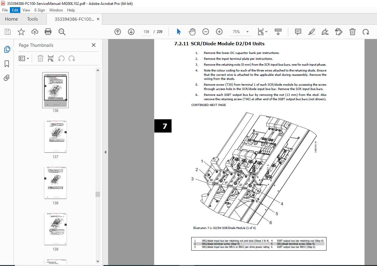
SCR/Diode Module D2/D4 Units:
- Power module removal
- Heatsink disassembly
- Thermal compound application
- Installation procedures
SCR/Diode Module D1/D3 Units:
- D1/D3 module procedures
Current Sensor:
- Sensor location
- Removal procedures
- Calibration considerations
Chapter 8: E-Frame Sizes (Assumed from content pattern)
- E-frame specific procedures
- Larger capacity drives
- Unique components
🎯 VLT FC SERIES SPECIFICATIONS:
FC 102 HVAC Drive: ✅ Variable torque optimization
✅ Energy savings for fans/pumps
✅ HVAC-specific features
✅ PID control built-in
✅ Sleep mode functionality
✅ Fire mode operation
FC 202 AQUA Drive: ✅ Water/wastewater applications
✅ Pump control features
✅ Constant/variable torque
✅ Built-in cascade control
✅ Dry-running protection
✅ Flow control
FC 302 AutomationDrive: ✅ Industrial automation
✅ Fully programmable
✅ Multiple control modes
✅ Fieldbus communication
✅ Advanced motion control
✅ Process control features
Common Features: ✅ PWM control
✅ Vector control capability
✅ Built-in PLC functionality
✅ Multiple I/O options
✅ Communication protocols
✅ Advanced diagnostics
✅ Energy optimization
Power Ranges: ✅ 380-480 VAC systems
✅ 525-690 VAC systems
✅ Multiple frame sizes
✅ Heavy duty/normal duty ratings
✅ Up to several hundred kW
💡 IDEAL FOR:
✅ Industrial maintenance technicians
✅ VFD service specialists
✅ HVAC service engineers
✅ Water treatment plant technicians
✅ Automation system integrators
✅ Electrical contractors
✅ Manufacturing maintenance departments
✅ Building management service teams
✅ Process control engineers
✅ Anyone servicing Danfoss drives
🌟 KEY BENEFITS:
- Three Drive Series: Complete coverage of FC 102, 202, and 302
- Comprehensive 209 Pages: Extensive technical documentation
- High Power Applications: D and E frame sizes
- Multiple Voltage Ranges: 380-690 VAC coverage
- Component-Level Repair: Detailed disassembly instructions
- Complete Test Procedures: Static and dynamic testing
- EMC Guidelines: Proper installation for electromagnetic compatibility
- Official Danfoss Documentation: Factory service procedures
- Minimize Downtime: Systematic troubleshooting reduces repair time
- Complete Fault Codes: Alarm database with corrective actions
📊 TECHNICAL CONTENT:
Power Conversion:
- Three-phase AC input
- Diode/SCR rectification
- DC bus intermediate circuit
- IGBT inverter output
- PWM output waveform
Control Technology:
- Microprocessor control
- Digital signal processing
- Vector control algorithms
- Scalar V/Hz control
- Sensorless operation
- Encoder feedback option
Protection Features:
- Overcurrent protection
- Overvoltage protection
- Undervoltage protection
- Overtemperature protection
- Ground fault protection
- Phase loss detection
- Motor thermal protection
Communication:
- Modbus RTU
- Profibus
- DeviceNet
- CANopen
- Ethernet options
- BACnet (HVAC)
⚙️ SERVICE HIGHLIGHTS:
Diagnostic Capabilities:
- Extensive fault logging
- Event history
- Operating parameters
- Trend monitoring
- Predictive maintenance
Test Equipment:
- Signal test board included in procedures
- Test cable specifications
- Multimeter testing
- Oscilloscope procedures
- Insulation testing
Calibration:
- Current sensor calibration
- Voltage calibration
- Temperature sensor calibration
- Control signal calibration
Component Testing:
- IGBT testing procedures
- Diode testing
- SCR testing
- Capacitor testing
- Sensor testing
- Fan testing
📥 DOWNLOAD INFORMATION:
- Instant Download: Immediate access after purchase
- Format: PDF with bookmarks for easy navigation
- Compatibility: Works on PC, Mac, tablet, smartphone
- Searchable: Full-text search for quick reference
- Printable: Print entire manual or specific sections
- High Quality: Clear diagrams, schematics, and photographs
- Bookmarked: Navigate easily to any chapter
- Professional: Official Danfoss documentation
⚠️ IMPORTANT NOTES:
- This is a professional service manual for qualified technicians
- Contains high voltage warnings (up to 690V)
- Official Danfoss documentation
- ESD precautions required
- Essential for maintaining drive performance
- Service requires electrical technician qualifications
- Some procedures require specialized test equipment
- Safety procedures must be followed
🔧 REQUIRED SERVICE EQUIPMENT:
- Digital Multimeter (true RMS)
- Oscilloscope
- Insulation Resistance Tester (Megger)
- Torx driver set
- Torque wrenches
- Signal generator
- Clamp-on ammeter
- Temperature measurement equipment
- ESD protection equipment
- Standard electrical tools
🌟 WHY CHOOSE THIS MANUAL?
This is the authentic Danfoss factory service manual, not third-party documentation. It contains proprietary diagnostic procedures, test methods, disassembly instructions, and repair procedures developed by Danfoss engineers. The VLT FC Series drives are sophisticated power conversion systems requiring factory-level service procedures to ensure safe and reliable operation.
The manual’s comprehensive coverage of three different drive series (HVAC, AQUA, and Automation) and multiple voltage ranges makes it an invaluable reference for service departments supporting diverse applications.
Order now for immediate download access to complete Danfoss VLT FC Series frequency converter service documentation!