Datex-Ohmeda Cardiocap II CG-Series Service Manual PDF
Original price was: $95.00.$30.95Current price is: $30.95.
Access the comprehensive Datex-Ohmeda Cardiocap II CG-Series service manual PDF for detailed troubleshooting, repairs, and adjustments on your medical monitor. This 276-page guide covers ECG, NIBP, SpO2, and gas measurement systems, including technical specifications, wiring diagrams, and module descriptions. Ideal for technicians seeking a reliable Datex Cardiocap CG series troubleshooting manual or Cardiocap 2 ECG monitor repair guide. Download instantly for precise Datex-Ohmeda monitor adjustment procedures and maintenance.
Description
Datex-Ohmeda Cardiocap II CG-Series Service Manual PDF DOWNLOAD
Description
This Datex-Ohmeda Cardiocap II CG-Series service manual PDF is an essential resource for biomedical engineers and technicians maintaining Datex Cardiocap CG series monitors. Packed with in-depth technical details, it provides step-by-step guidance on servicing, troubleshooting, and calibrating the Cardiocap 2 ECG monitor, including principles of operation for CO2/N2O, O2, ECG, NIBP, and SpO2 measurements. Whether you’re handling repairs or preventive maintenance, this manual ensures accurate diagnostics using wiring diagrams, block diagrams, and adjustment procedures.
File Details:
- Manual Name: CARDIOCAP™ II CG-Series Service Manual
- Models Covered: CG-Series (including CS, 2CS, 1G, 1GS, 2G, 2GS variants)
- Year: 1990
- Manual PDF Quality: High-quality scanned document with clear text, diagrams, and schematics
- No. of Pages: 276
The manual includes a detailed table of contents, list of figures, and appendices for easy navigation. Below is a neatly categorized extraction of the table of contents and list of figures, formatted for clarity:
Table of Contents
- 1. Contents
- 1.1 Table of contents
- 1.2 List of figures
- 1.3 List of tables
- 2. Warnings and Cautions
- 3. Introduction and Applicability of This Manual
- 3.1 Introduction and applicability of this manual
- 3.2 Summary of revision changes
- 3.3 Manual updates
- 3.3.1 CARDIOCAP™ II CG-series service manual changes
- 3.3.2 Record of manual updates carried out
- 3.4 Software changes
- 4. General Description
- 4.1 Typical performance of CARDIOCAP™ II CG-SERIES monitor
- 4.2 Technical specifications of CARDIOCAP™ II CG-SERIES monitor
- 4.3 Principle of operation
- 4.3.1 Principle of CO₂/N₂O measurement
- 4.3.2 Principle of O₂ measurement
- 4.3.3 Principle of ECG measurement
- 4.3.4 Principle of NIBP measurement
- 4.3.5 Principle of SpO₂ measurement
- 4.4 General block diagram
- 4.5 Wiring diagram
- 4.6 External connector configurations
- 4.6.1 Input/Output specifications
- 4.6.2 Connectors
- 5. Detailed Description of Modules
- 5.1 Gas sampling system
- 5.2 CO₂/N₂O measurements
- 5.2.1 Introduction
- 5.2.2 Photometer
- 5.2.3 Preamplifier board
- 5.2.4 CO₂/N₂O measuring board
- 5.2.5 O₂ measurement
- 5.3 ECG board
- 5.4 IPT (Invasive-Pleth-Temperature) board
- 5.5 NIBP measurement
- 5.5.1 NIBP board
- 5.5.2 Pneumatic unit
- 5.5.3 NIBP air pump
- 5.5.4 Safety valve
- 5.5.5 NIBP tubing
- 5.5.6 Twin hose
- 5.5.7 Blood pressure cuff
- 5.6 SpO₂ measurement
- 5.6.1 SpO₂ measuring board
- 5.6.2 SpO₂ processor board
- 5.6.3 SpO₂ connector I/O board
- 5.7 CPU board
- 5.8 Video control board
- 5.9 Power supply board
- 5.10 Mother board
- 5.11 Keyboard
- 5.12 Loudspeaker unit
- 5.13 Internal connector configurations
- 6. Service and Troubleshooting
- 6.1 General service information
- 6.2 Disassembly and reassembly
- 6.3 Troubleshooting
- 6.3.1 Monitor start-up sequence
- 6.3.2 Error messages
- 6.3.3 Troubleshooting in general
- 6.3.4 Gas sampling system troubleshooting
- 6.3.5 Gas measurement troubleshooting
- 6.3.6 O₂ measurement troubleshooting
- 6.3.7 ECG board troubleshooting
- 6.3.8 IPT board troubleshooting
- 6.3.9 NIBP board troubleshooting
- 6.3.10 SpO₂ measuring electronics troubleshooting
- 6.3.11 SpO₂ processor board troubleshooting
- 6.3.12 CPU board troubleshooting
- 6.3.12.1 Instructions after replacing the software or CPU board
- 6.3.13 Video control board troubleshooting
- 6.3.14 Power supply board troubleshooting
- 6.3.15 Mother board/Keyboard troubleshooting
- 6.3.16 Loudspeaker troubleshooting
- 6.4 Service mode
- 7. Adjustments
- 7.1 Adjustments after component replacements
- 7.2 Gas sampling system adjustment
- 7.3 CO₂ and N₂O measurement adjustments
- 7.3.1 Zero adjustments
- 7.3.2 Gain adjustments
- 7.3.3 Reference voltage adjustments
- 7.3.4 Temperature compensation adjustments
- 7.3.5 Pressure measurement offset and gain adjustments
- 7.4 Oxygen measurement adjustments
- 7.4.1 Offset(zero) adjustment
- 7.4.2 Gain adjustment
- 7.4.3 Temperature compensation adjustment
- 7.4.4 Frequency adjustment
- 7.5 ECG board adjustment
- 7.6 IPT board adjustment
- 7.7 NIBP board adjustment
- 7.8 SpO₂ processor board adjustment
- 7.9 CPU board adjustment
- 8. Functional Field Check Procedure
- 8.1 Preoperative check list
- 8.2 Checks after component replacements
- 8.3 Preventive maintenance check list
- 9. Spare Parts
- 9.1 Spare parts
- 9.2 Service accessories
- 12. Appendices
- A. Computer Output
- B. CCP-104 Graphics Printer
- C. CCK-104 Keyboard
- C.1 General Description
- C.1.1 Specifications
- C.1.2 Principle of operation
- C.1.3 General block diagram
- C.1.4 Connector configurations
- C.2 Detailed Description of Modules
- C.2.1 Keyboard
- C.2.2 Control board
- C.3 Service and Troubleshooting
- C.3.1 Disassembly and reassembly
- C.3.2 General troubleshooting
- C.3.3 Keyboard troubleshooting
- C.3.3.1 Keyboard test mode
- C.3.4 Control board troubleshooting
- C.3.5 Connecting cable troubleshooting
- C.4 Spare Parts
- C.4.1 Spare parts
- C.1 General Description
List of Figures
| Figure | Description | Page |
|---|---|---|
| 4.1 | CO₂/N₂O gas absorption spectra | 4-11 |
| 4.2 | Absorption coefficients of oxy- and deoxy-hemoglobin in the red and near-infrared regions | 4-15 |
| 4.3 | Absorption of infrared light in the finger | 4-16 |
| 4.4 | Finger clamp probe parts layout and schematic diagram | 4-17 |
| 4.5 | General block diagram | 4-19 |
| 4.6 | Wiring diagram | 4-20 |
| 5.1 | Gas sampling system schematic diagram | 5-4 |
| 5.2 | Gas sampling system layout (modification level 6 and higher) | 5-5 |
| 5.3 | CO₂/N₂O measuring system block diagram | 5-10 |
| 5.4 | Photometer | 5-11 |
| 5.5 | Synchronizing board parts layout and schematic diagram (modification level 6 and lower) | 5-12 |
| 5.5a | Synchronizing board parts layout and schematic diagram (modification level 7 and higher) | 5-12a |
| 5.6 | Preamplifier board parts layout and schematic diagram | 5-14 |
| 5.7 | CO₂/N₂O measuring board parts layout | 5-18 |
| 5.8 | CO₂/N₂O measuring board timing diagram and schematic diagram | 5-19 |
| 5.9 | O₂ measurement principle | 5-20 |
| 5.10 | ECG board block diagram | 5-23 |
| 5.11 | ECG board parts layout and schematic diagram (board modification level 1 and higher) | 5-24 |
| 5.12 | IPT board block diagram (CS, 2CS, 2G, 2GS) | 5-27 |
| 5.13 | IPT board parts layout (CS, 2CS, 2G, 2GS) | 5-28 |
| 5.14 | IPT connector board and IPT board schematic diagrams (CS, 2CS, 2G, 2GS) | 5-29 |
| 5.15 | IPT board block diagram (1G, 1GS) | 5-30 |
| 5.16 | IPT board parts layout (1G, 1GS) | 5-31 |
| 5.17 | IPT connector board and IPT board schematic diagrams (1G, 1GS) | 5-32 |
| 5.18 | Block Diagram of NIBP System (USA Version) | 5-40 |
| 5.19 | NIBP board parts layout and schematic diagram (part 1) | 5-41 |
| 5.19a | NIBP board parts layout and schematic diagram (part 1) (board modification level 5 and higher) | 5-41a |
| 5.20 | NIBP board schematic diagram (part 2) | 5-42 |
| 5.20a | NIBP board schematic diagram (part 2) (board modification level 5 and higher) | 5-42a |
| 5.21 | SpO₂ measuring board block diagram | 5-48 |
| 5.22 | SpO₂ measuring board parts layout, timing diagram and schematic diagram (part 1) | 5-49 |
| 5.22a | SpO₂ measuring board parts layout, timing diagram and schematic diagram (part 1) (board modification level 6 and higher) | 5-49a |
| 5.23 | SpO₂ measuring board signal waveforms and schematic diagram (part 2) | 5-50 |
| 5.23a | SpO₂ measuring board signal waveforms and schematic diagram (part 2) (board modification level 6 and higher) | 5-50a |
| 5.24 | SpO₂ processor board block diagram | 5-52 |
| 5.25 | SpO₂ processor board parts layout and schematic diagram | 5-53 |
| 5.26 | SpO₂ boards configuration | 5-54 |
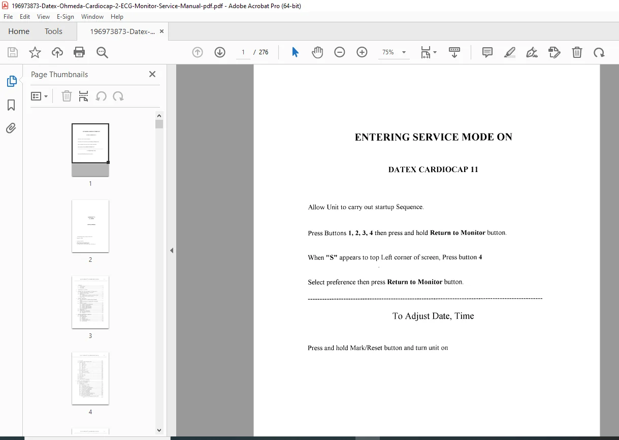
This Datex Cardiocap CG series troubleshooting manual also features service mode entry instructions, error message explanations, and spare parts lists, making it a complete Cardiocap 2 ECG monitor repair guide. With Datex-Ohmeda monitor adjustment procedures and medical equipment service manual download options, it’s perfect for ensuring optimal performance in clinical settings.
Don’t miss out on this invaluable tool—download the Datex-Ohmeda Cardiocap II CG-Series service manual PDF today and get your monitor back to peak condition instantly, saving time and costly repairs!