De La Rue 1250HS Banknote Counter Service Manual Technical Repair PDF
Original price was: $95.00.$28.95Current price is: $28.95.
Complete factory service manual for De La Rue 1250HS banknote counting machine. Comprehensive technical documentation covering mechanical & electrical systems, diagnostics, maintenance schedules, settings adjustments, component removal/replacement procedures. Includes detailed wiring diagrams, troubleshooting guides, spindle assembly instructions, vacuum system calibration, circuit board interconnections. Essential for technicians servicing high-speed note counters in banks, currency processing centers & cash handling facilities.
Description
De La Rue 1250HS Banknote Counter Service Manual Technical Repair Guide – PDF DOWNLOAD
DESCRIPTION
This is the official De La Rue 1250HS Banknote Counting Machine Service Manual (Document TP01313012 Rev. 00, dated May 2000), providing complete technical information for professional servicing, maintenance, and repair of this high-speed currency counter.
Machine Overview
The 1250HS is a microprocessor-controlled, vacuum-operated verify, batch and count note system designed as a stand-alone tabletop counter (also available in pedestal configuration). This precision machine counts banded banknotes and similar documents at speeds ranging from 25 to 40 notes per second with a capacity of 150 notes.
Complete Manual Structure
Preliminary Information:
- Technical bulletins and memoranda system
- Safety warnings and health & safety guidelines
- High voltage, high energy, and moving parts precautions
- Static sensitive device handling procedures
- Amendment record sheets
Section 1 – General Description:
- Introduction to 1250HS counter functionality
- Complete technical specifications:
- Electrical: 98-264V AC, 350W max power
- Mechanical: Desktop weight 20kg, pedestal 36kg
- Dimensions: 285mm H x 345mm W x 430mm D
- Document size range: 100mm x 50mm (min) to 200mm x 100mm (max)
- Document thickness: 0.06mm to 0.18mm
- Count speed: 25-40 notes per second
- Acoustic noise: 80dBA (desktop) / 74dBA (with shutters)
- Operating temperature: +10°C to +35°C
- Humidity range: 30% to 80% RH
- Barometric pressure: 650mBar to 1100mBar
Section 2 – Operating Instructions:
- Safety information for operators
- Machine overview and component identification
- Control panel layout and functions
- LCD display interpretation (10-digit display)
- Setup procedures and operational guidelines
- User guide for counting/verifying operations
Section 3 – Mechanical Description:
- Base Assembly construction details
- Covers and Shutters system explanation
- Feed Plate and Damper – mirror polished plate assembly, torsion spring mechanism, silicone fluid-filled damper for bounce prevention
- Feed Plate Gearbox Assembly – DC brushless motor drive, V pulley/belt combination, worm/worm wheel system, cam-operated link mechanism
- Spindle Assembly – five-spindle rotating housing, sun and planet gear arrangement, vacuum switching system, note detection via pressure drop sensor
- Spindle Drive Assembly – timing belt drive system, reduction gear, DC brushless motor specifications
- Vacuum system operation and air flow paths
- Note separation and collection mechanisms
Section 4 – Electrical Description:
- Electronic Architecture – single microprocessor system distributed over 4 PCBs
- Control Board – main processing unit with complete interconnection tables
- I/O Board – machine interface connections, sensor inputs, solenoid outputs
- Hall Effect Board – spindle speed sensing system
- Daughter Board – external connections (remote display, printer, PC data collection)
- Power Supply Unit (PSU) – switched mode power supply specifications
- Complete interconnection diagrams showing all cable routing
- Pin-out tables for all connectors:
- Control Board P1 (I/O Board interface)
- I/O Board P2 (Machine interface)
- Motor connections (Coil A/B/C, Hall sensors 1/2/3)
- Daughter Board P1 (Control Board interface – RS232)
- PSU connections (AC mains input, +30V DC output)
- Microswitches specifications (3 units – shutter sensors, note stop)
- Batching and stamping solenoid connections
- Cable forms with part numbers:
- Shutter motor: FB06000401
- Motor cableform: FB06133901
- Interboard: FB06133601
- Mains desktop: FB06133801
- Low voltage: FB06133504
Section 5 – Maintenance:
- First Line Maintenance schedule and procedures
- Precautions for safe servicing
- Main Filter Cleaning – transparent bowl removal, O-ring inspection/replacement using Loctite 415
- General Cleaning protocols for dust and dirt removal
- Vacuum Pump Motor Maintenance:
- Carbon blade inspection (minimum 13mm width requirement)
- Blade wear assessment procedures
- Pump disassembly/reassembly instructions
- Non-return valve inspection
- Vacuum and Pressure Relief Valves – ball seat inspection, cleaning procedures
- Electronic Component Checks – IC, plug, and socket verification
- Belt Inspection – wear assessment (cracks, nicks, kinks)
- External thermal trip connections and relay wiring
Section 6 – Diagnostics:
- Service Diagnostics comprehensive testing suite:
- Diagnostic 0 – Check Sum and firmware version display
- Diagnostic 1 – Sensor Check with 7-bar status display
- Diagnostic 2 – Vacuum Level Display with real-time measurement
- Diagnostic 3 – Display and Keyboard Test (all segments)
- Diagnostic 4 – Timed Feed Arm Test
- Diagnostic 5 – Batch Arm Test
- Diagnostic 6 – Timed Shutter Test
- Diagnostic 7 – Remote Display Test (includes oscillator frequency check)
- Diagnostic 8 – Spindle Start Delay selection (0, 0.4, 0.8 seconds)
- Diagnostic 10 – Serial Port Settings (baud rate, stop bits, parity, data bits)
- Diagnostic 11 – Printer Port Settings
- Diagnostic 13 – Continuous Machine Cycling test
- Diagnostic 14 – NOVRAM Initialization
- Diagnostic 15 – Spindle Speed Calibration
- Diagnostic 45 – Background Totals Display (lifetime counts, power ups, error logs)
- Hidden switch locations (H1, H2, H3, H4) on control panel
- Error code reference tables
- User error codes (U146-U149) explanations
- Troubleshooting procedures for diagnostic failures
Section 7 – Settings and Adjustments:
- Vacuum Settings – proper vacuum level calibration
- Tail Clamp and Feed Plate Adjustment – kiss point setting, alignment procedures
- Shutter Belt Fitting and Tensioning:
- Long belt installation and tensioning
- Short belt cutting and clamping under shutter carrier
- Idler pulley adjustment procedures
- Spindle Alignment – using alignment jig (T1200109)
- Spindle Timing – center spindle port orientation, timing adjuster procedures
- Backstop Adjuster positioning
- Spindle Speed calibration (24-40 notes per second range)
- Tension Spring adjustment – 6 securing positions, factory setting position 3
- I/O PCB Link Positions (LK1/LK2) – shutter operation defaults for different builds
Section 8 – Removal, Overhaul and Replacement:
- Tools Required – complete list of specialized tools
- Component Removal Procedures:
- Covers and shutters disassembly
- Spindle drive assembly removal
- Feed plate assembly extraction
- Feed gearbox assembly (motor replacement, belt removal)
- Damper assembly/feed arm assembly separation
- PSU removal and run capacitor access
- Note adjuster and riffler disassembly
- Spindle assembly complete removal procedure:
- Hall Effect sensor disconnection
- Vacuum pipe routing
- Spindle cover removal
- Base mounting screws (3mm Allen key)
- Timing adjuster arm disassembly
- Spindle shaft extraction
- Bearing removal (upper/lower/center)
- Circlip removal procedures
- Mains switch extraction
- Vacuum pump assembly removal
- Spindle Assembly Replacement:
- Bearing refitting sequence
- Alignment jig usage (part number T1200109)
- Center spindle port alignment (narrow port direction)
- O-ring inspection and replacement
- Timing adjuster installation
- Filter cap installation
- Illustrated Parts Lists with complete part numbers and quantities:
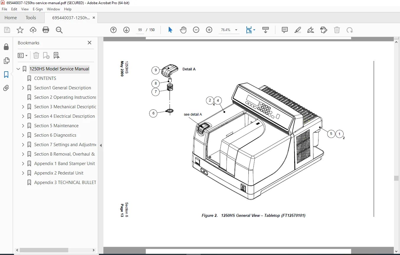
- Figure 2: 1250HS General View (FT12570101)
- Figure 3: 1250HS Basic Kit (FB03002001)
- Figure 4: Base Unit Assembly (multiple sub-items)
- Figure 5: Damper and Feed Arm Assembly (FB02138101)
- Figure 6: Damper and Feed Arm Sub Assembly (FB02120701)
- Figure 7: Feed Plate Sub-Assembly (FB02136501)
- Figure 10: Spindle Assembly details
- Figure 11: Spindle Drive Assembly (FB02125901)
- Figure 13: Riffler Assembly (FB02126301)
- Figure 14-15: Gearbox components
- Figure 16: Main Filter Assembly
- Figure 17: Vacuum Pump Assembly (FB03000601)
- Figure 18-19: Shutter Kit (FB03000501)
- Figure 22: Cooling Fan Assembly (FB02000301)
Appendix 1 – Band Stamper Unit:
- Optional band stamper accessory information
- Installation and operation procedures
Appendix 2 – Pedestal Unit:
- Pedestal version specifications
- Mounting and assembly details
Appendix 3 – Technical Bulletins/Memoranda:
- Amendment procedures
- Technical bulletin filing system
- Service manual update protocols
Key Technical Features Covered
✓ Complete wiring schematics and cable routing diagrams
✓ Microprocessor control system architecture
✓ Vacuum sensing and pressure control systems
✓ RS232 interface configuration (CMS operation)
✓ Brushless DC motor specifications and connections
✓ Carbon blade wear limits and replacement criteria
✓ NOVRAM initialization and data storage
✓ Speed calibration procedures (self-calibrating system)
✓ Acoustic noise specifications with/without shutters
✓ Environmental operating ranges and storage conditions
✓ Electromagnetic field susceptibility warnings
✓ COSHH-compliant solvent recommendations
✓ Static electricity discharge (ESD) precautions for MOS components
Who Should Use This Manual
- Banknote Counter Technicians – servicing currency processing equipment
- Cash Handling Service Engineers – maintaining high-speed counting machines
- Banking Equipment Specialists – repairing central bank counting systems
- Currency Processing Centers – in-house technical maintenance staff
- De La Rue Authorized Service Centers – official repair facilities
- Forensic Laboratory Equipment Managers – maintaining document verification systems
File Details
| Manual Name | De La Rue 1250HS Service Manual |
|---|---|
| Document Number | TP01313012 Rev. 00 |
| Models Covered | 1250HS (Desktop & Pedestal configurations) |
| Publication Date | May 2000 |
| Number of Pages | 150 pages |
| PDF Quality | Good – Scanned original factory manual with clear diagrams |
| Language | English |
Critical Safety Information Included
⚠ Class 1, 3-wire earthed product – Earth connection required for safety
⚠ High voltage warnings – Mains power safety protocols
⚠ High energy components – PSU arcing and burn hazards
⚠ Moving parts safety – Precautions during service with covers removed
⚠ Cable voltage identification – Test meter verification requirements
⚠ Static sensitive devices – MOS component handling procedures
This comprehensive service manual is essential for anyone responsible for maintaining, repairing, or servicing De La Rue 1250HS banknote counting machines. With detailed exploded-view diagrams, complete part numbers, step-by-step procedures, and diagnostic protocols, this manual provides everything needed to keep these high-speed currency counters operating at peak performance.
FILE DETAILS TABLE
| Specification | Details |
|---|---|
| Manual Name | De La Rue 1250HS Banknote Counting Machine Service Manual |
| Document Number | TP01313012 Rev. 00 |
| Models Covered | 1250HS (Desktop configuration), 1250HS with Pedestal |
| Publication Date | May 2000 |
| Number of Pages | 150 |
| PDF Quality | Good – Clear scanned factory manual with legible diagrams |
| Language | English |