DEUTZ TD3.674 (Tier 4) 750 708 T750 MLA 7 MLA-T 516 Articulated Loader Parts Manual – PDF DOWNLOAD
Original price was: $78.00.$22.95Current price is: $22.95.
DEUTZ TD3.674 (Tier 4) 750 708 T750 MLA 7 MLA-T 516 Articulated Loader Parts Manual – PDF DOWNLOAD
Description
DEUTZ TD3.674 (Tier 4) 750 708 T750 MLA 7 MLA-T 516 Articulated Loader Parts Manual – PDF DOWNLOAD
IMAGES PREVIEW OF THE MANUAL:
DESCRIPTION:
DEUTZ TD3.674 (Tier 4) 750 708 T750 MLA 7 MLA-T 516 Articulated Loader Parts Manual – PDF DOWNLOAD
Introduction
- For your safety and continued proper operation, use only genuine XPRT® Genuine Parts. When ordering service parts, specify the correct part number, full description, quantity required, the unit model number and serial number.
- The model and serial number decal for this unit are located on the left chassis upright. Manitou Americas reserves the right to make changes or improvements in the design or construction of any part of the unit without incurring the obligation to
- install such changes on any previously delivered units. Purchase equivalent, quality XPRT tires for your loader. Contact your dealer for replacement tire information. Replacement batteries are not provided by Manitou Americas. Battery specifi cations are listed in Electrical section where the battery is shown. ALL REPLACEMENT BATTERIES MUST BE PURCHASED LOCALLY.
How to Use This Manual
- “Right” and “Left” are determined from a position sitting on the seat and facing forward. Unless otherwise indicated, all parts page graphics are shown as viewed from the front left. If the view is from a different perspective, a directional arrow on the lower left corner will identify the front of the machine.
- Items shown in the parts list that do not have part numbers are shown for reference purposes only and are NOT available for purchase. Dimensions are in inches unless otherwise specifi ed. Refer to the abbreviations table to the right for various fastener descriptions. Standard hardware torque values are provided at the end of this manual. For parts requiring non-
- standard torque values, the correct torque value will appear on the parts page graphic or parts list next to the corresponding item number
Schematics
Hydraulic and electrical schematics are located in the operator’s manual and service
manual
Abbreviations
A Ampere
AR As Required
ASSY Assembly
CB Carriage Bolt
CP Cotter Pin
CS Cap Screw (Hexagon Head)
CYL Cylinder
DIA Diameter
FHCS Flat Head Cap Screw
FOPS Falling Object Protective Structure
G Grams
GR Grade
HB Hex Bolt
HLN Hex Lock Nut
HN Hex Nut
HP High Pressure
HYD Hydraulic
INS Insert
LN Lock Nut
LT Left
LW Lock Washer
M Meter or Meters
MM/mm Millimeter
N/A Not Available, Not Applicable
N•m Newton meter
NPT National Pipe Thread
OS Oversized
ROPS Roll Over Protective Structure
RT Right
SHCS Socket Head Cap Screw
SLTD Slotted
SN Serial Number or Slotted Nut
SQ Square
TOPS Tip Over Protective Structure
US Undersized
V Volt
W/ With
W/O Without
TABLE OF CONTENTS:
DEUTZ TD3.674 (Tier 4) 750 708 T750 MLA 7 MLA-T 516 Articulated Loader Parts Manual – PDF DOWNLOAD
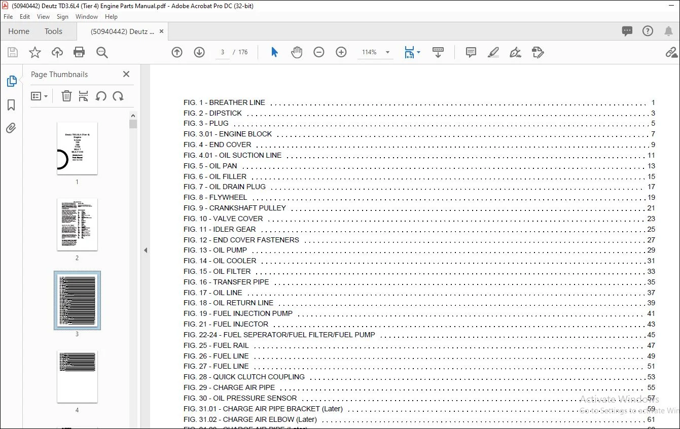
FIG 1 – BREATHER LINE 5
FIG 2 – DIPSTICK 7
FIG 3 – PLUG 9
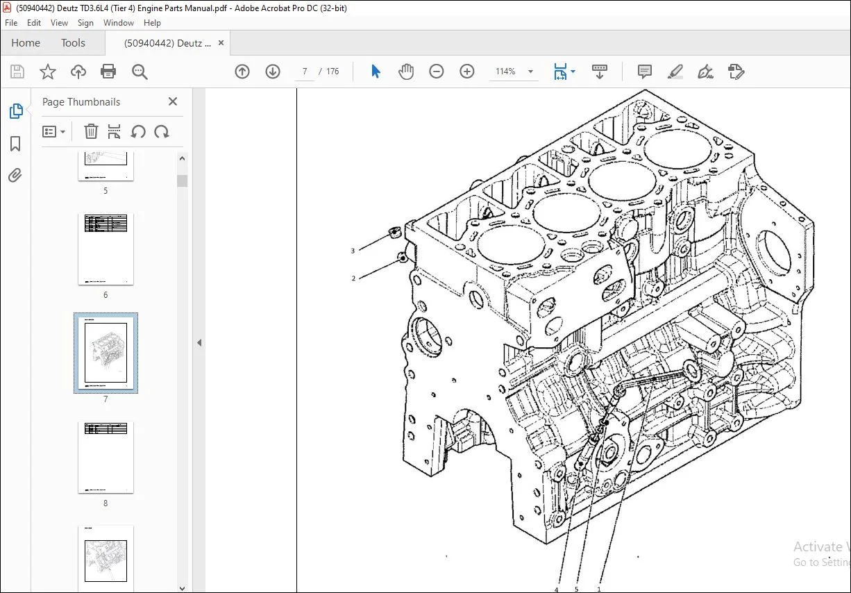
FIG 3 01 – ENGINE BLOCK 11
FIG 4 – END COVER 13
FIG 4 01 – OIL SUCTION LINE 15
FIG 5 – OIL PAN 17
FIG 6 – OIL FILLER 19
FIG 7 – OIL DRAIN PLUG 21
FIG 8 – FLYWHEEL 23
FIG 9 – CRANKSHAFT PULLEY 25
FIG 10 – VALVE COVER 27
FIG 11 – IDLER GEAR 29
FIG 12 – END COVER FASTENERS 31
FIG 13 – OIL PUMP 33
FIG 14 – OIL COOLER 35
FIG 15 – OIL FILTER 37
FIG 16 – TRANSFER PIPE 39
FIG 17 – OIL LINE 41
FIG 18 – OIL RETURN LINE 43
FIG 19 – FUEL INJECTION PUMP 45
FIG 21 – FUEL INJECTOR 47
FIG 22-24 – FUEL SEPERATOR/FUEL FILTER/FUEL PUMP 49
FIG 25 – FUEL RAIL 51
FIG 26 – FUEL LINE 53
FIG 27 – FUEL LINE 55
FIG 28 – QUICK CLUTCH COUPLING 57
FIG 29 – CHARGE AIR PIPE 59
FIG 30 – OIL PRESSURE SENSOR 61
FIG 31 01 – CHARGE AIR PIPE BRACKET (Later) 63
FIG 31 02 – CHARGE AIR ELBOW (Later) 65
FIG 31 03 – CHARGE AIR PIPE (Later) 67
FIG 31 04 – CHARGE AIR PIPE HOSE (Later) 69
FIG 31 – CHARGE AIR PIPE 71
FIG 32 – ELECTRONIC CONTROL UNIT (ECU) 73
FIG 33 – V-PULLEY 75
FIG 34 – WATER PUMP 77
FIG 35a – THERMOSTAT HOUSING (Later) 79
FIG 35 – THERMOSTAT HOUSING (Early) 81
FIG 36 – COOLANT LINE 83
FIG 37 – COOLANT PIPE (Early) 85
FIG 38a – EGR COOLER (Later) 87
FIG 38 – EGR COOLER (Early) 89
FIG 39 – EGR CONNECTOR 91
FIG 40 – INTAKE EXPANSION JOINT 93
FIG 41 – EGR BRACKET 95
FIG 42 – EGR COOLANT PIPE 97
FIG 43 – EGR COOLANT LINE 99
FIG 44 – EGR BRACKET 101
FIG 45 – COOLANT LINE PLUG 103
FIG 39a – EXHAUST PIPE (Later) 105
FIG 46 01 – EXHAUST MANIFOLD (SN 12460170 and Up) 107
FIG 46 – EXHAUST MANIFOLD (SN 12460169 and Before) 109
FIG 47 – TURBOCHARGER 111
FIG 48 – EXHAUST CONNECTION 113
FIG 49 – V-BELT 115
FIG 50 01 – ALTERNATOR (Later) 117
FIG 50 – ALTERNATOR (Early) 119
FIG 51 – ALTERNATOR ADJUSTMENT BRACKET 121
FIG 52 – ALTERNATOR BRACKET 123
FIG 53 – STARTER 125
FIG 54 – PLUG-IN CONNECTOR 127
FIG 55 – RELAY 129
FIG 56 – STARTER RELAY CABLE 131
FIG 57 – PROTECTION CAP 133
FIG 58 – PLUG-IN CONNECTOR 135
FIG 59 – WIRE HARNESS FASTENERS 137
FIG 60 01 – WIRE HARNESS (Later) 139
FIG 60 – WIRE HARNESS (Early) 141
FIG 61 – TACHO-ALTERNATOR 143
FIG 62 – TACHOMETER SENSOR 145
FIG 62a – PRESSURE SENSOR 147
FIG 63 – FLYWHEEL HOUSING 149
FIG 63a – FLYWHEEL HOUSING BRACKET 151
FIG 64 – GLOW PLUGS 153
FIG 65 01 – DOC PARTICULATE FILTER (Later) 155
FIG 65 02 – DOC TEMPERATURE TRANSMITTER (Later) 157
FIG 65 – DOC BRACKET 159
FIG 65a – DOC RISER 161
FIG 67 – DOC CLAMP 163
FIG 75 – GASKETS 165
Appendix A:Pages Index 167
Appendix B:Parts Index 168
Contact us: [email protected]
https://vimeo.com/738923399
PLEASE NOTE:
- This is the SAME manual used by the dealers to troubleshoot any faults in your vehicle. This can be yours in 2 minutes after the payment is made.
- Contact us at [email protected] should you have any queries before your purchase or that you need any other service / repair / parts operators manual.
S.m